QIE0763-0XZRW103 RF Controlled 3-Way Switch
Advanced Control Technologies, Inc.
Click to zoom
Application Details
- Equipment Class
- DXX - Part 15 Low Power Communication Device Transmitter
- Date of Grant
- Jan 30, 2008
- Application Purpose
- Original Equipment
- Date of Application
- Jan 30, 2008
- Equipment Note
- ZRW103 RF Controlled 3-Way Switch
- Frequency Range
- 908.40000000 - 908.40000000
- Country
- United States
Documents & Files
Document Text
Text extracted from the exhibit documents filed with the FCC. Open a document above to read the original.
Users Manual
Z-Wave ZRW103 Series 200 Instructions, Release 2.2 P/D 012108 HomePro by ADVANCED CONTROL TECHNOLOGIES, INC. 0763-01 1 Z-Wave Radio Frequency (RF) Controlled, 120 VAC, Wall Mounted Switch, 3-Way, Series 200, Release 2.2 ZRW103 HomePro RF Home Automation ZRW103 WALL MOUNTED SWITCH The ZRW103 Wall Mounted 3-Way Switch is a component of the HomePro lighting control system. Wire the Wall Mounted Switch in place of the standard wall switch according to the diagram above and program from the Wireless Controller to operate loads. Inclusion of this Switch on the ZTH100 Wireless Controller menu allows remote ON/OFF control of lamps connected. This Wall Mounted Switch is designed to work with other Z-Wave enabled devices. Z-Wave nodes of other types can be added to the system and will also act as repeaters if they support this function of repeating the signal received to other modules in the system. As part of a Z-Wave network, the ZRW103 will also act as a wireless repeater to insure that commands intended for another device in the network are received. This is useful when the device would otherwise be out of the radio range of the wireless controller. There are no field repairable assemblies on this unit.. If service is needed, the unit must be returned where purchased. DANGER! SHOCK HAZARD. Read and understand these instructions before installing. This device is intended for installation in accordance with the National Electric code and local regulations in the United States, or the Canadian Electrical Code and local regulations in Canada. It is recommended that a qualified electrician perform this installation. Make sure the load controlled by the switch does not exceed 2400 watts. For indoor use only. Retain instructions for future use. INSTALLATION Wire this Switch in place of a current wall switch according to the diagram above. When used, AS101’s are required to be wired to the same line (or neutral) which is also wired to the master unit as well as the load being controlled, and not wired to any other neutral. If multiple neutrals are tied together in one box, separate the neutrals to preserve the integrity of the ZRW103 circuit. Caution! Do not wire unit “live” (with power on the circuit) and do not allow the yellow wire to contact line voltage, neutral or ground or you will damage the device. Refer to your Controller operating instructions to add this module under the command of the Wireless Controller. Shown with supplied Decora TM trim plate Note: This module must be “Included in the Network” only where it will be permanently installed. The proper opera- tion of this node in the mesh network is dependent on it knowing its location with respect to other nodes. You cannot “test bench” configure this module, then install. Z-Wave ZRW103 Series 200 Instructions, Release 2.2 P/D 012108 HomePro by ADVANCED CONTROL TECHNOLOGIES, INC. 0763-01 2 INCLUDING ZRW103 TO THE NETWORK STEP 1.. Prepare the Controller to include a unit to the network by adding it to a group (method of adding a node to the network). Refer to controller instructions. STEP 2. The ZRW103 must be in its permanently installed location. Tap either the top or bottom of the ZRW103 once. STEP 3. You should see an indication on your Controller that the “DEVICE WAS INCLUDED” in the network. NOTE: If you have trouble adding the ZRW103 to a group it may be that the Home ID and Node ID were not cleared from it after testing. You must first “RESET UNIT” with your controller to remove it from the network. If using the ZTH100, select “SETUP” and scroll to “RESET UNIT” Although adding it to a group includes it in the network, removing it from a group does not remove it from the network. If removed from a group, it functions as a repeater (only). “RESET UNIT” removes it completely from the network. BASIC OPERATION (Local Control) The switch paddle on the ZRW103 allows the user to: • Turn the attached load on or off. • Include or exclude the module from the Z-Wave system • Control other Z-Wave enabled devices. Also, when a controller prompts you to “Send Node ID” or to “Press Button on Unit”, quickly tap the switch on or off once to satisfy those instructions. • Tapping top of switch turns the load attached ON. • Tapping bottom of switch turns the load attached OFF. • Pressing and holding switch does not effect the load attached to the ZRW103, but will allow dimming and brightening of Z-Wave dimmers if associated (see below for details). LED indication The LED on the ZRW103 will turn on when the load attached is ON. The LED can be user configured however to turn ON when the load attached is OFF, if so desired, to act as a night light. See ADVANCED OPERATION section. The ZRW103 will flicker its LED when it is transmitting to any of its 2 groups. This can be changed if desired. See ADVANCED OPERATION section. Auxiliary Switch The ZRW103 supports the AS101 auxiliary switch to provide 3-way or 4-way operation. Remote Control The ZRW103 will respond to BASIC and BINARY commands that are part of the Z-Wave system. Refer to your controller’s instructions as to whether your controller can transmit those commands. Internal circuit protection The ZRW103 internal circuitry is protected by an internal fuse. This internal fuse is factory serviceable only. Check your home circuit breakers before concluding that the product must be returned to manufacturer for repair at a nominal charge. ADVANCED OPERATION All On/All Off The ZRW103 supports the ALL ON/ ALL OFF commands. The ZRW103 can be set to respond to ALL ON and ALL OFF commands four different ways. Refer to your controller for information on how to set the ZRW103 to operate in the manner you desire. Some controllers may be only able to set certain settings of ALL ON/ALL OFF response. The four different ways the ZRW103 can be setup to respond to ALL ON and ALL OFF commands are: Z-Wave ZRW103 Series 200 Instructions, Release 2.2 P/D 012108 HomePro by ADVANCED CONTROL TECHNOLOGIES, INC. 0763-01 3 1. ZRW1…
Text truncated - open the document above for the full version.
Block Diagram
Chk'd App'd Date QA ADVANCED CONTROL TECHNOLOGIES, INC. Title Tolerances Except as noted Resistance: Capacitance: Revisions A New Design 11 DWG # SH OF THE INFORMATION IN THIS DOCUMENT IS THE EXCLUSIVE PROPRIETARY PROPERTY OF ADVANCED CONTROL TECHNOLOGIES, INC. IT IS DISCLOSED WITH THE UNDERSTANDING THAT ACCEPTANCE OR REVIEW BY THE RECIPIENT CONSTITUTES AN AGREEMENT BY THE RECIPIENT (1) TO HOLD THIS INFORMATION IN STRICT CONFIDENCE, AND (2) NOT TO DISCLOSE, DUPLICATE, COPY, OR USE THIS INFORMATION, IN WHOLE OR IN PART, FOR ANY OTHER PURPOSE OTHER THEN THAT FOR WHICH DISCLOSED. Decimal: +/- 0.020" Angle: +/- 1 Deg. Fraction: +/- 1/100" Dwn: Saw Filter Passive Coupling Network LNA Mixer IFAMP/ Limiter FM Detector Data Slicer TX Power Amp Divide by N Phase Comparator & Charge Pump Divide by R Control Voltage Controlled Oscillator Low-Pass Filter Micro-Controller 32 MHz Crystal Osc VCO Freq MHz Tx: 908.42 RX: 908.275 TX RX IF Freq: 145KHz VCO Coil Zensys ZM2102 USZ-wave ASIC Module Flash Memory Push Buttons Low Voltage Power Supply +3.3VDC Relay Circuitry +15VDC AS101 interface circuitry Yellow Traveler Wire 120VAC/ 60Hz Line In Switched 120VAC/60Hz to Load (20A max) Clock PData Strobe DIO lock ZRW103 Block Diagram MAS 01-14-2008 0763R2A N L LD
Cover Letter(s)
Attention: Application Examiner Federal Communications Commission January 9, 2008 Re: Request for confidentiality, FCC ID: QIE0763-0X and QIE0766-0X Applicant: Advanced Control Technologies, Inc. To whom it may concern, Request is hereby submitted by Advanced Control Technologies, Inc. to withhold permanently from public review certain portions of the application for equipment certification for the referenced FCC identifiers. This request for confidentiality is made pursuant to 47 CFR 0.457(d) of the FCC Rules. In particular, the following sections of the application are to be kept permanently confidential: • Schematics • Detailed Block diagrams • Detailed Operational/Functional Description Rationale for request for confidentiality: Advanced Control Technologies, Inc. has invested considerable time and materials in research and development to produce the referenced product. Disclosure of the permanently confidential portions of this application to competitors would not only give them significant competitive advantages in developing similar products, but would also disclose successful implementation of unpublished, leading edge technology developed by us. The fee for confidentiality should have been submitted along with the fee for certification. If you have questions or need further information, please contact the undersigned. Sincerely, Mark A. Scott Hardware Engineering Manager Advanced Control Technologies, Inc.
External Photos
ZRW103 EXTERNAL PHOTOS
ID Label/Location Info
HomePro TM RF Wall SwitchModel ZRW103A Resistive Load...20A , 120 Volts AC, 60 Hz Motor Load...1 HP S/N Incandescent Load...960W 908.42 MHz CONFORMS TO ANSI/UL STD. 244A CERTIFIED TO CAN/CSA C22.2 No. 177 FCC ID: QIE0763-0X Canada IC: 4436A-07630X Advanced Control Technologies, Inc., Indianapolis, IN Made in China Series 200, Rel 2.2 BLK-Line WHI-Neutral. BLU-Load GRN-Grnd YEL-AS101 ZRW103A Series 200 Product Label Artwork Radius corners of label 1/8” (or .125”) PRODUCT LABEL To be made from 80Y (UL file PGDQ2.MH13653) or equvalent. Must comply with UL969. 2.000” 1.000” Date Code: 3B54A HomePro TM RF Wall Switch Model ZRW103W Resistive Load...20A , 120 Volts AC, 60 Hz Motor Load...1 HP S/N Incandescent Load...960W 908.42 MHz CONFORMS TO ANSI/UL STD. 244A CERTIFIED TO CAN/CSA C22.2 No. 177 FCC ID: QIE0763-0X Canada IC: 4436A-07630X Advanced Control Technologies, Inc., Indianapolis, IN Made in China Series 200, Rel 2.2 BLK-Line WHI-Neutral. BLU-Load GRN-Grnd YEL-AS101 ZRW103W Series 200 Product Label Artwork Radius corners of label 1/8” (or .125”) PRODUCT LABEL To be made from 80Y (UL file PGDQ2.MH13653) or equvalent. Must comply with UL969. 2.000” 1.000” Date Code: 3B54A HomePro TM RF Wall SwitchModel ZRW103I Resistive Load...20A , 120 Volts AC, 60 Hz Motor Load...1 HP S/N Incandescent Load...960W 908.42 MHz CONFORMS TO ANSI/UL STD. 244A CERTIFIED TO CAN/CSA C22.2 No. 177 FCC ID: QIE0766-0X Canada IC: 4436A-07660X Advanced Control Technologies, Inc., Indianapolis, IN Made in China Series 200, Rel 2.2 BLK-Line WHI-Neutral. BLU-Load GRN-Grnd YEL-AS101 ZRW103I Series 200 Product Label Artwork Radius corners of label 1/8” (or .125”) PRODUCT LABEL To be made from 80Y (UL file PGDQ2.MH13653) or equvalent. Must comply with UL969. 2.000” 1.000” Date Code: 3B54A Label location
Internal Photos
ZRW103 INTERNAL PHOTOS
Schematics
1 2 3 4 5 6 78 ABCD 8 7 6 5 4 3 2 1 D CBA R370R W1 FB21K@100MHz L33.9nH C1 10uF R3010K VCC R341K R3110K CS 1 SO 2 WP 3 GND 4 SI 5 SCK 6 HOLD 7 VCC 8 U2AT25128N FB11K@100MHz VCC C1133nF RXD/ADC3_ZWTXD/ADC2_ZWTRAIC/ADC1_ZWZEROX/ADC0_ZWSCK_ZWP1.5_ZWPWM/INT0_ZWINT1_ZWRESET_N_ZWMOSI_ZWMISO_ZWMOSI_ZW MISO_ZW SCK_ZWP1.5_ZW SW1 PB-SW LED1BLUE RXD/ADC3_ZWTXD/ADC2_ZWTRIAC/ADC1_ZWZEROX/ADC0_ZWSCK_ZWPWM/INT0_ZWINT1_ZWMOSI_ZWMISO_ZWRESET_N_ZW RXDTXDTRIACZEROXSCKINT1P1.5MOSIMISORESET_N 1 2 3 4 5 6 7 8 9 10 11 12 13 14 15 16 17 18 19 20 J1 HEADER 10X2 A C17N.M. SW2 PB-SW VCC AD2AD1PWM R27 100K Themsitor R28N.M.R29N.M. R264K75 VCC VCC R22N.M.R23N.M. R24N.M.R25N.M. VCC VCC R3210K R3310K VCC VCC R35N.M. R360R VCC C183.3pF 123456 J3HEADER 6' R2 1K R3 1K R4 1K R5 1K R6 N.M. R7 1K R8 1K R9 1K R10 1K R11 1KR12 1KR14 1K R15 0R R16 N.M. R17 N.M. 13-Oct-2006 ZDW120(45606)/ZDW103(45607) RF PCB Circuit 23 Sheenway Technology Development Ltd. 1.2 TITLESHEET NO.DATEORG. SHEET TOTALVERSION EP1 1 EP2 2 EP3 3 EP4 4 EP5 5 EP6 6 EP7 7 EP8 8 EP9 9 EP10 10 EP11 11 EP12 12 EP13 13 EP14 14 EP15 15 EP16 16 EP17 17 EP18 18 U1 ZM2102 VCC These will be required for ZDW103. To be added for future expansion use. TRIAC/ADC1_ZWTXD/ADC2_ZWZEROX/ADC0_ZW R13 1K P1.5_ZW 1 2 34 ABCD 4 3 2 1 D CBA 13-Oct-2006ZM2102 Z-Wave Module 33 Sheenway Technology Development Ltd. 1.1 TITLESHEET NO.DATEORG. SHEET TOTALVERSION NC 1 NC 2 RESET_N 3 P1.7/INT1 4 P1.6/PWM/INT0 5 P1.5 6 P1.4/SCK 7 VPP 8 P1.3/MOSI 9 P1.2/MISO 10 DVDD_1O 11 DVDD 12 MAIN 13 DVDD 14 SUPP 15 DVDD 16 P1.1/ADC3/RXD 17 P1.0/ADC2/TXD 18 P0.1/ADC1/TRIAC 19 P0.0/ADC0/ZEROX 20 VSS 21 XOSC_Q2 22 XOSC_Q1 23 AVDD_CO 24 VSS 25 AVDD_SY 26 AVDD_RF 27 TX_IND 28 RF_IO 29 RX_IND 30 AVDD_IF 31 VSS 32 EP_GND 0 U1ZW201 X132MHz C524pF C622pF L312nHL13.3nH C15.6pF IN 1 GND 2 GND 3 OUT 4 U3908MHz C833nF C933nF C1033nF C1133nF C17100nFC1847pFC1947pFC20100nF VCC VCC AVDD AVDD AVDD AVDD L41K@100MHz C71uF C151uF VCC AVDD EP11mmEP21mmEP31mmEP41mmEP51mmEP61mmEP71mmEP81mmEP91mmEP101mmEP111mmEP121mmEP131mmEP141mmEP151mmEP161mmEP171mm EP181mm VCC RESET_N RESET_N INT1_NINT0_NP1.5MISOSCKMOSIRXDTRIACZEROXTXD TXD RXDTRIACZEROXMISOMOSISCKP1.5INT0_NINT1_N 50ohm Trace
Test Report
TEST REPORT Report Number: 3137903MIN-001 Project Number: 3137903 Testing performed on the ZRW103I RF Controlled Wall Mounted Switch FCC ID: QIE0763-0X Industry Canada ID: 4436A-07630X to 47 CFR Part 15. 249:2006 RSS- 210, Issue 7, 2007 For Advanced Control Technologies Inc. Test Performed by: Test Authorized by: Intertek Testing Services NA, Inc. 7250 Hudson Blvd., Suite 100 Oakdale, MN 55128 Advanced Control Technologies Inc. 8076 Woodland Drive Indianapolis, IN 46278 Prepared by: Date:December 12, 2007 Uri Spector Reviewed by: Date:December 12, 2007 Norman Shpilsher This report is for the exclusive use of Intertek's Client and is provided pursuant to the agreement between Intertek and its Client. Intertek's responsibility and liability are limited to the terms and conditions of the agreement. Intertek assumes no liability to any party, other than to the Client in accordance with the agreement, for any loss, expense or damage occasioned by the use of this report. Only the Client is authorized to copy or distribute this report and then only in its entirety. Any use of the Intertek name or one of its marks for the sale or advertisement of the tested material, product or service must first be approved in writing by Intertek. The observations and test results in this report are relevant only to the sample tested. This report by itself does not imply that the material, product, or service is or has ever been under an Intertek certification program. This report must not be used to claim product endorsement by A2LA, NIST nor any other agency of the U.S. Government. EMC Report No: 3137903MIN-001 FCC ID: QIE0763-0X IC ID: 4436A-07630X Page 2 of 23 TABLE OF CONTENTS 1.0 GENERAL DESCRIPTION..........................................................................................................3 1.1 Product Description; Test Facility......................................................................................4 1.3 Environmental conditions ..................................................................................................5 1.4 Measurement uncertainty..................................................................................................6 1.5 Field Strength Calculation .................................................................................................6 2.0 TEST SUMMARY..........................................................................................................................7 3.0 TEST CONDITIONS AND RESULTS........................................................................................8 3.1 Transmitter field strength of emissions .............................................................................8 3.2 Out of Band of Emissions................................................................................................11 3.3 Bandwidth of Emissions ..................................................................................................12 3.4 Transmitter power line conducted emissions ..................................................................15 3.5 Digital device radiated emissions ....................................................................................18 3.6 Digital device conducted emissions ................................................................................20 4.0 TEST EQUIPMENT.....................................................................................................................22 EMC Report No: 3137903MIN-001 FCC ID: QIE0763-0X IC ID: 4436A-07630X Page 3 of 23 1.0 GENERAL DESCRIPTION Model: ZRW103I Type of EUT: RF Controlled Wall Mounted Switch Serial Number: N/A FCC ID: QIE0763-0X Industry Canada ID: 4436A-07630X Related Submittal(s) Grants: None Company: Advanced Control Technologies Inc. Customer: Mr. Mark Scott Address: 8076 Woodland Drive Indianapolis, IN 46278 Phone: (317) 337-0100 ext. 214 Fax: (317) 337-0200 Test Standards: FCC Part 15.249 RSS–210, Issue 7, 2007 RSS-Gen, Issue 1, 2005 47 CFR, Part 15:2005, §15.107 and §15.109, Class B Other Type of radio: Stand -alone Module Hybrid Date Sample Submitted: November 27, 2007 Test Work Started: November 27, 2007 Test Work Completed: December 12, 2007 Test Sample Conditions: Damaged Poor (Usable) Good EMC Report No: 3137903MIN-001 FCC ID: QIE0763-0X IC ID: 4436A-07630X Page 4 of 23 1.1 Product Description; Test Facility Product Description: ZRW103I Operating Frequency 908.39 MHz Modulation: FSK Emission Designator: Antenna(s) Info: Integral Antenna Antenna Installation: User Professional Factory Transmitter power configuration: Internal rechargeable battery External power source 120VAC 230VAC 400VAC 3.6 VDC Other: Amp. 50Hz 60Hz Test Methodology: Emission measurements were performed according to the procedures in ANSI C63.4-2003. All field strength radiated emissions measurements were performed in the semi-anechoic chamber, and for each scan, the procedure for maximizing emissions in were followed. All field strength radiated tests were performed at an antenna to EUT distance of 3 meters, unless stated otherwise in the "Justification Section" of this Application Special Test Arrangement: As a hand-held device the EUT was rotated through three orthogonal axes to determine and tested with the maximum emissions Test Facility: The test site facility used to collect the radiated and conducted measurement data is located at 7250 Hudson Blvd., Suite 100, Oakdale, Minnesota. This test facility has been accredited by A2LA (Certificate No. 1427.01) Justification: None EMC Report No: 3137903MIN-001 FCC ID: QIE0763-0X IC ID: 4436A-07630X Page 5 of 23 1.2 EUT Configuration The equipment under test was operated during the measurement under the following conditions: - Standby - Continuous - Continuous transmission (see below) - Test program (customer specific) - Operating modes of the EUT: No. Description 1 The special test mode which allowed transmit continuously was used and load light was ON 2 Cables: No. Type Length De…
Text truncated - open the document above for the full version.
Test Setup Photos
Test Setup Photos
Contact Information
Applicant
Josh Hansen(Regulatory Engineer)
Technical Contact
Advaced Control TechnologiesMark Scott
[email protected]317-337-0100
8076 Woodland Drive · Indianapolis, Indiana · United States
Test Firm
Intertek Testing ServicesUri Spector
Technical Specifications
| # | Rule Parts | Frequency Range | Power Output |
|---|---|---|---|
| 1 | 15C | 908.4 MHz - 908.4 MHz | - |
Other Applications from Advanced Control Technologies, Inc.

QIE0810-01
Oct 20, 2011Dimmer
Equipment Class
DXT - Part 15 Low Power Transceiver, Rx Verified
QIE0791-01
Oct 27, 2010Wireless Switch
Equipment Class
DXT - Part 15 Low Power Transceiver, Rx Verified
QIE0792-01
Aug 24, 2010Wall Mounted Dimmer
Equipment Class
DXT - Part 15 Low Power Transceiver, Rx Verified
QIE0797-01
Jul 21, 2010Wall Mounted Dimmer
Equipment Class
DXT - Part 15 Low Power Transceiver, Rx Verified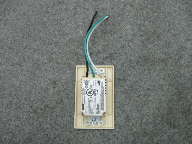
QIE0738-02
Jan 20, 2010Wireless Duplex Receptacle
Equipment Class
DXX - Part 15 Low Power Communication Device Transmitter