QLXCDL0236Central Door Lock
Tera Tron GmbH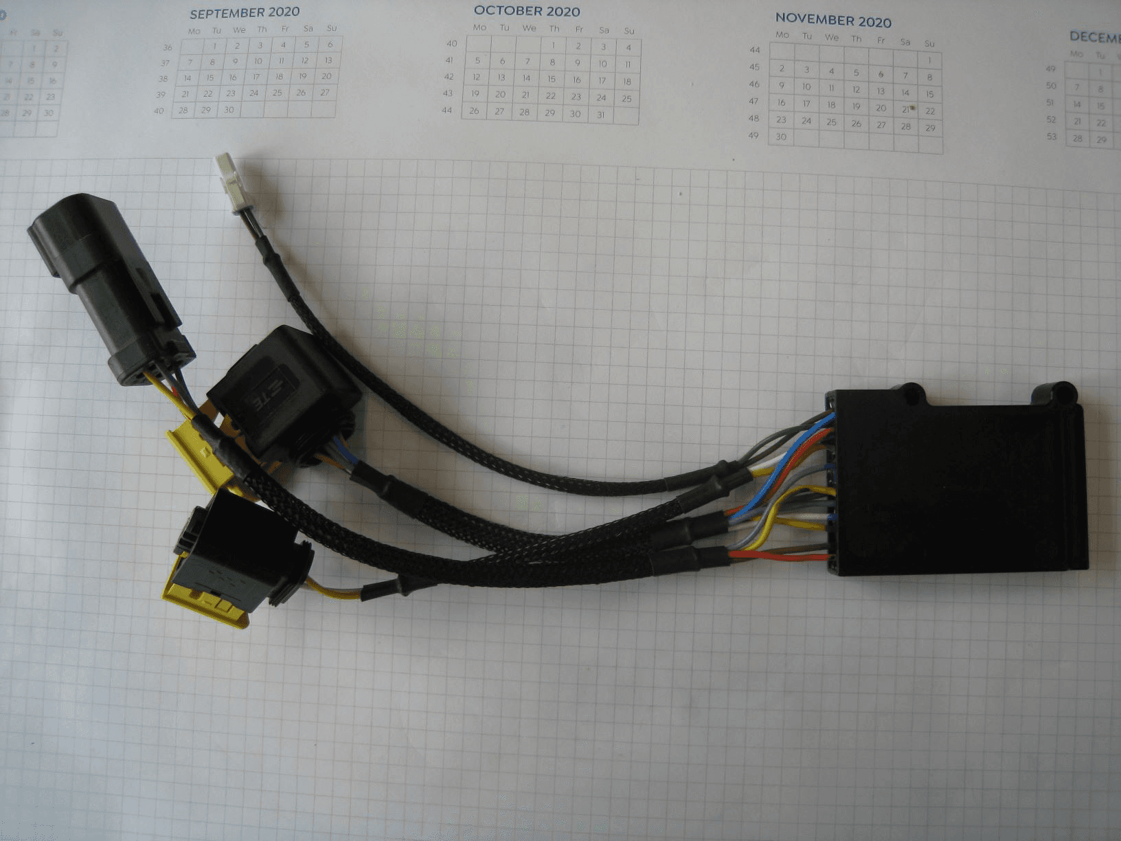
Click to zoom
Application Details
- Equipment Class
- DXX - Part 15 Low Power Communication Device Transmitter
- Date of Grant
- Mar 05, 2020
- Application Purpose
- Original Equipment
- Date of Application
- Feb 12, 2020
- Equipment Note
- Central Door Lock
- Frequency Range
- 916.50000000 - 916.50000000
- Company
- Tera Tron GmbH
- Country
- Germany
Documents & Files
Document Text
Text extracted from the exhibit documents filed with the FCC. Open a document above to read the original.
Users Manual
Functional description The main function of the system is to lock / unlock the mechanical door lock, and to open the cabin door via a RF remote control transmitter key (868/916MHz) with the electronic box as RF receiver/transceiver. Tyco HDSCS1,5 1-1670730-1 black Volvo PN 993364 central door locking motor opening support motor power cable coming from cabin 2 recept. 2 recept. 4 recept. rotor switch electronic box PCB is moulded in potting material 14 cm 0,75 mm² 50 cm 0,5 1 cm 0,75 mm² 14 cm 0,75 mm² 2 tab Tyco HDSCS1,5 1-1418448-2 black Volvo PN 993360 Tyco HDSCS1,5 2-1418448-1 gray Volvo PN ? Tyco HDSCS1,5 2-1670730-1 gray Volvo PN ? Tyco HDSCS1,5 1-1418469-1 black Volvo PN 993370 Tyco HDSCS1,5 1-1703773-1 black Volvo PN 993371 Tyco HDSCS1,5 3-1418448-2 green Volvo PN ? Tyco HDSCS1,5 3-1670730-1 green Volvo PN ? 3 tab 2 tab 5 tab 2 recept. tab = Sealed Tab Contacts = Stecker recept. = Sealed Receptacle Contacts = Buchse 10 wires, direct soldered on the PCB Transmitter with mechanical key, 3 buttons and 2 multi-colour LED Picture 1 shows the door lock mechanism with tow fitted motors and CDL-OS controller with all connectors, the rotor switch, and the RF remote control transmitter key. Abbreviations: CDL = Central Door Lock OS = Opening Support General Function The system is powered directly from the vehicle battery (24V system). Both motors are switched by a full bridge driver in the electronic box. The CDL motor has an internal switch for signalling the mechanical position to the electronic controller. The OS motor has an integrated strong spring for pulling the motor back into the “zero position”, so the OS motor needs no switch inside. The system can be used in both 12V and 24V systems. The CDL and OS motors are 12V motors. Voltage and current of the motors are fully controlled by the electronic –> results are a constant force in the full temperature range and a protection against overload and overheat. The rotor switch monitors the information of a fully closed cabin door. Power consumption in idle mode: < 8 mA Power consumption with CDL motor working: < 5 A Power consumption with OS motor working: < 9 A Wiring Harness The harness is shown in picture 1. The following diagram shows the assignment of the connectors and the wiring colors: + Battery M M CDL Electronic GND T11 T13 CDL Motor (lock/ unlock) OS Motor (opening support) door position closed open position unlock lock T22 T21 Rotor Switch T33 T45 T43 T42 T31 T41 T44 yel yel red brn grn brn blk blk blue gry yel T46 yel Power 28V red brown brn green wht wht green brn CDL0236 Compliance Statements Document no. CDL0236 Compliance Statements Project CDL0236 Document for FCC and IC Creation date: 11.10.2019 Revision Generate Approved Confidentiality Page Document 1.0 MSC RHE Strictly confidential 1 of 1 CDL0236 Compliance Statements CDL0236 Compliance Statements Compliance Statements FCC The title “CAUTION TO USERS” or “FCC/IC WARNING NOTE” or relevant title and “Changes or modifications not expressly approved by the party responsible for compliance could void the user’s authority to operate the equipment.” This device complies with Part 15 of the FCC Rules. Operation is subject to the following two conditions: (1) this device may not cause harmful interference, and (2) this device must accept any interference received, including interference that may cause undesired operation. Compliance Statements IC This device complies with Industry Canada licence-exempt RSS standard(s). Operation is subject to the following two conditions: (1) this device may not cause interference, and (2) this device must accept any interference, including interference that may cause undesired operation of the device. Le présent appareil est conforme aux CNR d'Industrie Canada applicables aux appareils radio exempts de licence. L'exploitation est autorisée aux deux conditions suivantes : (1) l'appareil ne doit pas produire de brouillage, et (2) l'utilisateur de l'appareil doit accepter tout brouillage radioélectrique subi, même si le brouillage est susceptible d'en compromettre le fonctionnement.
Cover Letter(s)
FCC, Request for non-disclosure Date: 21-Nov-2018 RF_501, Issue 8 Page 1 of 1 Company Name: 7layers GmbH Address: Borsigstr. 11 City: 40880 Ratingen Country: Germany To: Telefication B.V., Dept. FCC TCB Edisonstraat 12A 6902 PK ZEVENAAR The Netherlands Subject: Request for confidentiality FCC ID: QLXCDL0236 Reference number: ###### Dear FCC TCB, 1. Long-Term Confidentiality Pursuant to 47 CFR Section 0.459(a) & (b), we hereby requests non-disclosure and confidential treatment of the following materials submitted in support of FCC certification application: Bill(s) of Material Block Diagrams Operational Description Schematic Diagrams Tune-up Procedure Above materials contain secrets, proprietary and technical information, which would customarily be guarded from competitors under 47 CFR, section 0.457(d)(2). Disclosure or publication or any portion of this company confidential material to other parties could cause substantial competitive harm and provide unjustified benefits for competitors. 2. Short-Term Confidentiality (STC) Pursuant to Public Notice DA 04-1705 of the Commission’s policy, in order to comply with the marketing regulations in 47 CFR §2.803 and the importation rules in 47 CFR §2.1204, applicant hereby requests Short-Term Confidential treatment of the following materials (See notes below): Internal Photos User’s Manual Test Set-up Photos External Photos Justification: These documents contain detailed system and equipment description and related information about the product, which Tera Tron GmbH considers to be proprietary. This information should never get into the possession of competitors, which would be harmful for our business. Date: 06.02.2020 Name and signature of applicant: Teoman Soner Sunar Notes: 1) A document or type of document can only have ONE type of confidentiality! 2) Short-Term confidentiality is in principle for 45 days from date of grant; it can be extended max 3 times (total time 180 days max.)! The planned date should stated in the RF731 application form. 3) FCC must be informed when marketing begins earlier. 4) Release takes place automatically thus extension must be requested in time. Telefication does not remind you of this! 5) Request for extension or for release must be received by Telefication at least 7 days before date of actual marketing or before expiration of the STC period
ID Label/Location Info
CDL0236 Label Draft Document no. CDL0236 Label Draft Project CDL0236 Document for FCC and IC Creation date: 11.10.2019 Revision Generate Approved Confidentiality Page Document 1.0 MSC RHE Strictly confidential 1 of 1 CDL0236 Label Draft CDL0236 Label for FCC and IC Label size approx. 40x20mm Label contains: Brand = „TeraTron“ FCC / IC Model = „CDL0236“ FCC ID = „QLXCDL0236“ IC ID = „4430A-CDL0236“ TeraTron Model: CDL0236 FCC ID: QLXCDL0236 IC: 4430A-CDL0236
Test Report
Test Laboratory: 7layers GmbH Borsigstrasse 11 40880 Ratingen Germany Note: The following test results relate only to the devices specified in this document. This report shall not be reproduced in parts without the written approval of the test laboratory. 7layers GmbH Geschäftsführer/ Borsigstraße 11 Managing Directors: Registergericht/registered: a Bureau Veritas 40880 Ratingen, Germany Frank Spiller Düsseldorf HRB 75554 Group Company T +49 (0) 2102 749 0 Bernhard Retka USt-Id.-Nr./VAT-No. DE203159652 F +49 (0) 2102 749 350 Alexandre Norré-Oudard Steuer-Nr./TAX-No. 147/5869/0385 www.7layers.com Commerzbank AG Account No. 303 016 000 Bank Code 300 400 00 IBAN DE81 3004 0000 0303 0160 00 Swift Code COBADEFF FCC Measurement/Technical Report on CDL0236 TeraTron FCC ID: QLXCDL0236 IC: 4430A-CDL0236 Report Reference: MDE_TERA_1904_FCC_01_rev01 Test report Reference: MDE_TERA_1904_FCC_01_rev01 Page 2 of 33 TABLE OF CONTENTS 1 Applied Standards and Test Summary 3 1.1 Applied Standards 3 1.2 FCC-IC Correlation table 4 Measurement Summary /Signatures 5 Revision History 5 2 Administrative Data 6 2.1 Testing Laboratory 6 2.2 Project Data 6 2.3 Applicant Data 6 2.4 Manufacturer Data 6 3 Test object Data 7 3.1 General EUT Description 7 3.2 EUT Main components 8 3.3 EUT Setups 9 3.4 Operating Modes 9 3.5 Product labelling 9 4 Test Results 10 4.1 Field strength of Fundamental / Radiated power output 10 4.2 Field Strength of Harmonics / Spurious radiated emissions 12 4.3 Occupied bandwidth 21 5 Test Equipment 24 6 Antenna Factors, Cable Loss and Sample Calculations 26 6.1 LISN R&S ESH3-Z5 (150 kHz – 30 MHz) 26 6.2 Antenna R&S HFH2-Z2 (9 kHz – 30 MHz) 27 6.3 Antenna R&S HL562 (30 MHz – 1 GHz) 28 6.4 Antenna R&S HF907 (1 GHz – 18 GHz) 29 6.5 Antenna EMCO 3160-09 (18 GHz – 26.5 GHz) 30 6.6 Antenna EMCO 3160-10 (26.5 GHz – 40 GHz) 31 7 Photo Report 31 8 Setup Drawings 32 9 Measurement Uncertainties 33 Test report Reference: MDE_TERA_1904_FCC_01_rev01 Page 3 of 33 1 APPLIED STANDARDS AND TEST SUMMARY 1.1 APPLIED STANDARDS Type of Authorization Certification for an Intentional Radiator. Applicable FCC Rules Edition of FCC Rules: October 1, 2018 Prepared in accordance with the requirements of FCC Rules and Regulations as listed in 47 CFR Ch.1 Parts 2 and 15. The following subparts are applicable to the results in this test report. Part 2, Subpart J - Equipment Authorization Procedures, Certification Part 15, Subpart C – Intentional Radiators § 15.201 Equipment authorization requirement § 15.207 Conducted limits § 15.209 Radiated emission limits; general requirements § 15.249 Operation within the bands 902-928 MHz, 2400-2483.5 MHz, 5725-5875 MHz, and 24.0-24.25 GHz. Note: ANSI C63.10–2013 is applied. Summary Test Results: The EUT complied with all performed tests as listed in chapter 0 Measurement Summary / Signatures. Test report Reference: MDE_TERA_1904_FCC_01_rev01 Page 4 of 33 1.2 FCC-IC CORRELATION TABLE Correlation of measurement requirements for Momentarily (incl. Periodically) Operated Devices and Remote Control from FCC and IC Radio equipment Measurement FCC reference IC reference Conducted emissions on AC Mains § 15.207 RSS-Gen Issue 5: 8.8 Transmitter spurious radiated emissions § 15.209 RSS-Gen Issue 5: 6.13/8.9/8.10; RSS-210 Issue 9: 2.5 Field strength of Fundamental § 15.249 RSS-210 Issue 9: 2.5.1 RSS-Gen Issue 5: 6.12, 8.9 Operation within the bands 902-928 MHz, 2400-2483.5 MHz, 5725-5875 MHz, and 24.0-24.25 GHz. §15.249 RSS-210, Issue 9: Annex B Test report Reference: MDE_TERA_1904_FCC_01_rev01 Page 6 of 33 2 ADMINISTRATIVE DATA 2.1 TESTING LABORATORY Company Name: 7layers GmbH Address: Borsigstr. 11 40880 Ratingen Germany The test facility is also accredited by the following accreditation organisation: Laboratory accreditation no: DAkkS D-PL-12140-01-01 D-PL-12140-01-02 D-PL-12140-01-03 FCC Designation Number: DE0015 FCC Test Firm Registration: 929146 ISED CAB Identifier DE0007; ISED#: 3699A 2.2 PROJECT DATA Responsible for testing and report: M.Sc. Joel Asongwe Date of Report: 2020-02-11 Testing Period: 2019-11-13 to 2020-01-09 2.3 APPLICANT DATA Company Name: TeraTron GmbH Address: Martin-Siebert-Str. 5 51647 Gummersbach Germany Contact Person: Mr. Markus Schmidt 2.4 MANUFACTURER DATA Company Name: Address: Please see Applicant Data Contact Person: Test report Reference: MDE_TERA_1904_FCC_01_rev01 Page 7 of 33 3 TEST OBJECT DATA 3.1 GENERAL EUT DESCRIPTION Kind of Device product description SRD Transceiver, Central Door Lock, operating in 916.5 MHz frequency band Product name CDL0236 Type TeraTron Declared EUT data by the supplier Voltage Type DC Normal Voltage 12.0 V Low Voltage 7.0 V High Voltage 32.0 V Normal Temperature 25 °C Low Temperature -40 °C High Temperature +85 °C Specific product description for the EUT The EUT is a Central Lock Door device used to lock or unlock all the doors of a vehicle The EUT provides the following ports: Enclosure Special software used for testing Provided by the manufacturer Antenna type / gain Internal PCB loop antenna / -15dBi Transmitter operating frequencies 916.5 MHz The main components of the EUT are listed and described in Chapter 3.2. Test report Reference: MDE_TERA_1904_FCC_01_rev01 Page 8 of 33 3.2 EUT MAIN COMPONENTS Sample Name Sample Code Description EUT A DE1400000bb02 radiated sample Sample Parameter Value Serial No. DUT916MHz_2 HW Version 0236.01.05 SW Version Aktuell_F210_EMC_FUNK_916_5MHz Comment Used for all measurements General description of ancillary equipment Device Details (Manufacturer, Type Model, OUT Code) Reason for using --- --- --- General description of auxiliary equipment Device Details (Manufacturer, HW, SW, S/N) Description --- --- --- Test report Reference: MDE_TERA_1904_FCC_01_rev01 Page 9 of 33 3.3 EUT SETUPS This chapter describes the combination of EUTs and ancillary equipment used for testing. Setup No. Combination of EUTs Description Setup_01 EUT A Setup for radiated measurements: Output power and Spurious emissions…
Text truncated - open the document above for the full version.
Test Setup Photos
7layers GmbH Geschäftsführer/ Borsigstraße 11 Managing Directors: Registergericht/registered: a Bureau Veritas 40880 Ratingen, Germany Frank Spiller Düsseldorf HRB 75554 Group Company T +49 (0) 2102 749 0 Bernhard Retka USt-Id.-Nr./VAT-No. DE203159652 F +49 (0) 2102 749 350 Alexandre Norré-Oudard Steuer-Nr./TAX-No. 147/5869/0385 www.7layers.com Commerzbank AG Account No. 303 016 000 Bank Code 300 400 00 IBAN DE81 3004 0000 0303 0160 00 Swift Code COBADEFF Photo Report on Test Setups Central Door Lock CDL0236 FCC ID: QLXCDL0236 IC: 4430A-CDL0236 Test Report Reference: MDE_TERA_1904_FCC_Photo_Setups TEST REPORT REFERENCE: MDE_TERA_1904_FCC_Photo_Setups Page 2 of 3 Photo 1: Test setup for radiated measurements below 30 MHz Photo 2: Test setup for radiated measurements below 1 GHz TEST REPORT REFERENCE: MDE_TERA_1904_FCC_Photo_Setups Page 3 of 3 Photo 3: Test setup for radiated measurements above 1 GHz
Contact Information
Applicant
Rainer Helberg(Mr.)
Technical Contact
Tera Tron GmbHRainer Helberg
[email protected]0049226180820
Martin-Siebert-Str. 5 · Gummersbach · Germany
Non-Technical Contact
Tera Tron GmbHRainer Helberg
[email protected]0049226180820
Test Firm
7layers GmbHBernhard Retka
Technical Specifications
| # | Rule Parts | Frequency Range | Power Output |
|---|---|---|---|
| 1 | 15C | 916.5 MHz - 916.5 MHz | - |
Other Applications from Tera Tron GmbH
QLXKRP0320
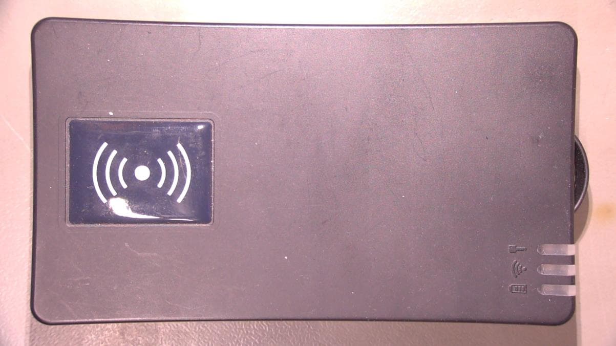
Dec 03, 2023Mobile Vehicle Key Reader
Equipment Class
DXX - Part 15 Low Power Communication Device Transmitter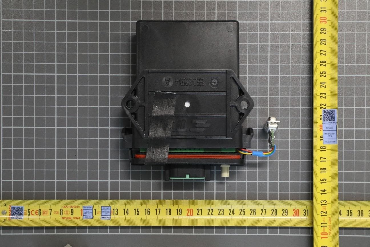
QLXBSS255R
Jun 05, 2023Protective Field Reader
Equipment Class
DCD - Part 15 Low Power Transmitter Below 1705 kHz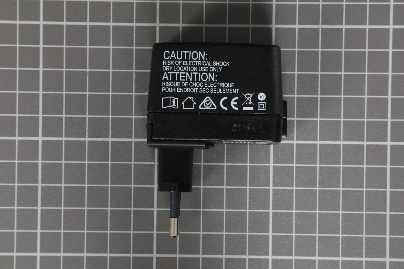
QLXKR0304
May 09, 2021Desktop KeyReader Plus
Equipment Class
DXX - Part 15 Low Power Communication Device Transmitter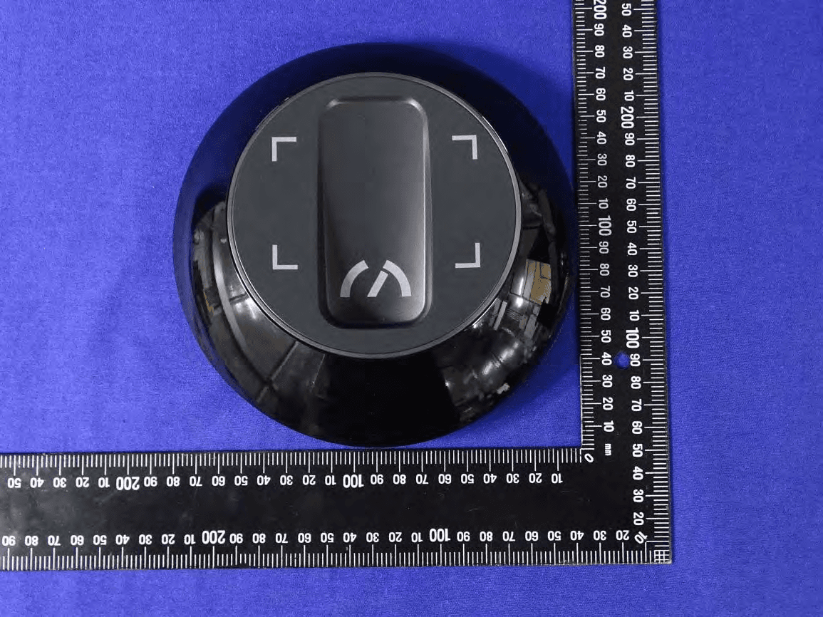
QLXKR0164
May 20, 2020Service Key Reader
Equipment Class
DCD - Part 15 Low Power Transmitter Below 1705 kHz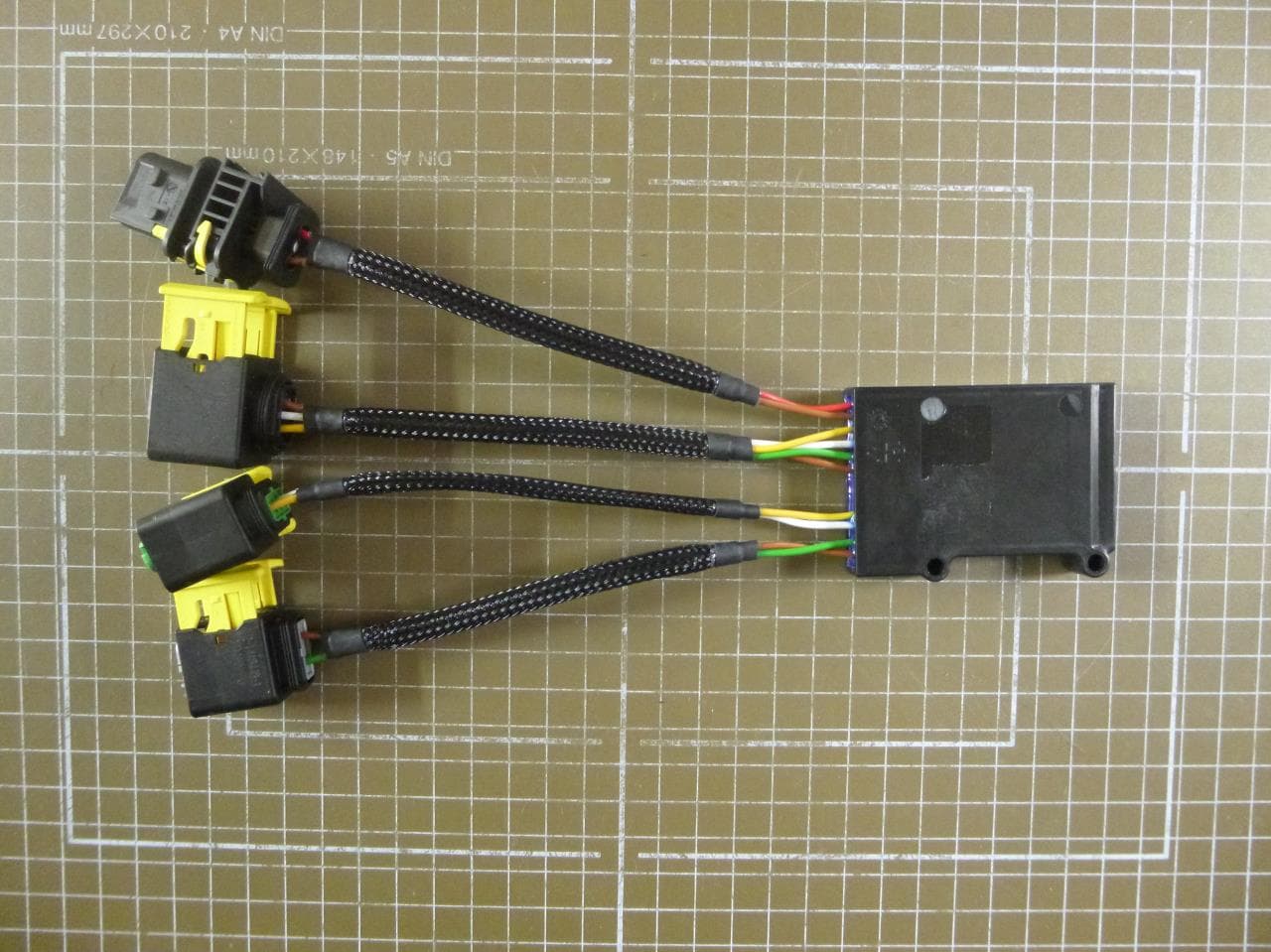
QLXCDLOS
Mar 18, 2014Transceiver
Equipment Class
DXT - Part 15 Low Power Transceiver, Rx Verified