QLXKRP0320Mobile Vehicle Key Reader
Tera Tron GmbH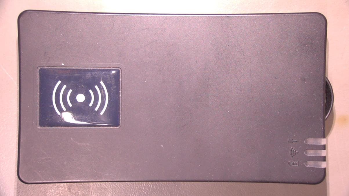
Click to zoom
Application Details
- Equipment Class
- DXX - Part 15 Low Power Communication Device Transmitter
- Date of Grant
- Dec 03, 2023
- Application Purpose
- Original Equipment
- Date of Application
- Dec 03, 2023
- Equipment Note
- Mobile Vehicle Key Reader
- Frequency Range
- 13.56000000 - 13.56000000
- Company
- Tera Tron GmbH
- Country
- Germany
Documents & Files
Document Text
Text extracted from the exhibit documents filed with the FCC. Open a document above to read the original.
Users Manual
Mobile KeyReader Plus 2 Manual Mobile KeyReader Plus 2 ©TeraTron GmbH Page 1 of 17 Document version 1.3 Date: 01/02/2023 Author: Marcel Mörchen Mobile_KeyReader Plus_2_EN.doc Mobile KeyReader Plus 2 Mobile KeyReader Plus 2 Manual Mobile KeyReader Plus 2 ©TeraTron GmbH Page 2 of 17 Document version 1.3 Date: 01/02/2023 Author: Marcel Mörchen Mobile_KeyReader Plus_2_EN.doc Contents 1 Introduction ................................................................................................................................... 3 2 Mechanical layout ......................................................................................................................... 5 3 Overview of the LED status displays ............................................................................................ 5 4 Configuration of the Mobile KeyReader Plus 2 ............................................................................ 6 5 Operating the Mobile KeyReader Plus 2. ................................................................................... 11 6 Setting up the Connection for Operation as Spare Device for the Huf KeyReader.................... 13 7 Operating the Mobile KeyReader Plus 2 .................................................................................... 15 7.1 Battery Status Display ............................................................................................................. 15 7.2 Status Read Key ..................................................................................................................... 15 8 FAQ ............................................................................................................................................. 16 9 Regulatory notes ......................................................................................................................... 17 Mobile KeyReader Plus 2 Manual Mobile KeyReader Plus 2 ©TeraTron GmbH Page 3 of 17 Document version 1.3 Date: 01/02/2023 Author: Marcel Mörchen Mobile_KeyReader Plus_2_EN.doc 1 Introduction The Mobile KeyReader Plus 2 is a mobile device for reading out the vehicle data saved in the vehicle key. After successful reading, the data is transmitted to a target system (KAI server). Data can be transmitted via USB or via an RF interface (WLAN). Figure 1. Typical system configuration Scope of delivery Mobile KeyReader Plus 2 hand-held wit belt clip Mobile KeyReader Plus 2 charging station with USB connection USB power adaptor with 4 adaptor plugs USB cable Carrier strap Commissioning To configure the Mobile KeyReader Plus 2 on a PC, a driver must be installed on the PC. Please fol- low the instructions in the ISPI manual to do so. Please note that you need local administrator rights for the installation of the driver. Before commissioning, the Mobile KeyReader Plus 2 should be completely charged for at least 8 hours. To do so, connect the USB power pack with the power supply via the matching connection plug. Afterwards, the Mobile KeyReader Plus 2 can either be charged with the provided USB cable or with the charging station. To use the USB cable, open the slider on the side of the hous- ing. WLAN router KAI server Mobile KeyReader Plus 2 Desktop PC USB Mobile KeyReader Plus 2 Manual Mobile KeyReader Plus 2 ©TeraTron GmbH Page 4 of 17 Document version 1.3 Date: 01/02/2023 Author: Marcel Mörchen Mobile_KeyReader Plus_2_EN.doc As soon as the Mobile KeyReader Plus 2 is connected with the power supply, the device turns on automatically and the charging process starts. The LED with the battery icon informs the user about the charge state of the battery. (Once the battery is fully charged, the LED turns green if the cable is connected.) Please note that a fully charged battery keeps the device ready for operation for approximately 10 hours. The USB port of a PC might not provide permanent power to charge the Mobile KeyReader Plus 2. To make sure that the device is ready for operation in the morning, it should be charged over- night with the provided power pack. Connection to a PC is only recommended for configuration of the Mobile KeyReader Plus 2. If the Mobile KeyReader Plus 2 is not used over longer periods, it should be switched off. Please note that the Mobile KeyReader Plus 2 turns on by itself if the USB cable is connected and cannot be turned off. Therefore, the device should not be connected to a USB port in case of longer interruptions of operation to prevent unintended reactivation. If the Mobile KeyReader Plus 2 should be completely discharged, it may happen that the device can- not complete its boot process (indicated by the blue flashing LED. In this case, the device has to be charged completely with the provided power pack for approximately 8 hours. Display and operating elements The Mobile KeyReader Plus 2 features 3 multi-coloured LEDs that inform the user about the current operating status. The LEDs all have an underlying symbol. There is an LED for the key reading func- tion (symbol: key), one for the connection status to the server (symbol: waves), and one for the battery status (symbol: battery). Section 3 contains a detailed description. The contacts for the charging cradle are located on the opposite end, and a micro USB connection as well as a switch are safely located beneath a slider. The switch can be operated with a pointed object. The Mobile KeyReader Plus 2 can be turned on and off with the switch. For turning the device off, the switch must be actuated for at least 2 seconds. Once you let go of the switch, the Mobile KeyReader Plus 2 switches into standby mode. This is signalled by a flashing blue LED. If you want to return the Mobile KeyReader Plus 2 to the factory settings, press the switch for at least 10 seconds while the device is turned on. A so-called "factory reset" takes place. With this reset, all key data and settings are deleted. The micro USB port is redundant for connecting the Mobile KeyReader Plus 2 via the charging stati…
Text truncated - open the document above for the full version.
Cover Letter(s)
Declaration of no Antenna Specification (Part 15C Devices) Federal Communications Commission Equipment Authorization Division, Application Processing Branch 7435 Oakland Mills Road Columbia, MD 21048 Innovation, Science and Economic Development Canada Spectrum Engineering Branch 3701 Carling Avenue, Building 94 Ottawa, Ontario K2H 8S2 Declaration of no Antenna Specification (Part 15C Devices) All required RF testing according to Part 15C was performed Radiated for this model. Therefore, no specific antenna specification is required and will not be submitted as a part of the technical documentation. This declaration is applicable for the model: KRP0320 with FCC ID: QLXKRP0320 Please do not hesitate to contact us for further explanations or comments. Sincerely, 2023-12-01 Signature Date Printed Name of Signee: Christopher Marx Company: IB-Lenhardt AG Address: Heinrich-Hertz-Allee 7, 66386 St Ingbert, Germany Phone: +49 6894 3893 811 Email: [email protected]
External Photos
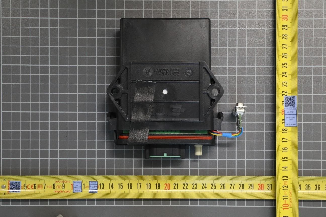
External Photos:
RF Exposure Info
1 (62) Copyright © Verkotan 2023 Document ID: FCC SAR report_KeyReader Plus ID5951_07092023.docx SAR Compliance Test Report Date of Report 7/09/2023 Client’s Contact person: Christopher Marx Number of pages: 62 Responsible Test engineer: Jesper Varis Testing laboratory: Verkotan Oy Elektroniikkatie 17 90590 Oulu Finland Client: TeraTron GmbH Martin-Siebert-Str. 5, 51647 Gummersbach Germany Tested device Mobile KeyReader Plus 2 Related reports: - Testing has been carried out in accordance with: 47CFR §2.1093 Radiofrequency Radiation Exposure Evaluation: Portable Devices FCC published RF exposure KDB procedures IEC/IEEE 62209-1528, 2020 Measurement procedure for the assessment of specific absorption rate of human exposure to radio frequency fields from hand-held and body-mounted wireless communication devices Documentation: The test report must always be reproduced in full; reproduction of an excerpt only is subject to written approval of the testing laboratory Test Results: The EUT complies with the requirements in respect of all parameters subject to the test. The test results relate only to devices specified in this document Date and signatures: 07.09.2023 Laboratory Manager 2 (62) Copyright © Verkotan 2023 Document ID: FCC SAR report_KeyReader Plus ID5951_07092023.docx TABLE OF CONTENTS 1. SUMMARY OF SAR TEST REPORT ......................................................................................................... 4 1.1 TEST DETAILS ......................................................................................................................................................................................... 4 1.2 MAXIMUM RESULTS .......................................................................................................................................................................... 4 1.2.1 Standalone SAR............................................................................................................................................................................... 5 1.2.2 Simultaneous Transmission SAR ........................................................................................................................................ 5 1.2.3 Maximum Drift ................................................................................................................................................................................. 5 1.2.4 Measurement Uncertainty........................................................................................................................................................ 5 2. DESCRIPTION OF THE DEVICE UNDER TEST (DUT)............................................................................... 6 2.1 SUPPORTED FREQUENCY BANDS AND OPERATIONAL MODES .............................................................................. 7 2.2 SIMULTANEOUS TRANSMISSION .............................................................................................................................................. 7 2.3 TEST EXEMPTIONS .............................................................................................................................................................................. 8 2.3.1 FCC ......................................................................................................................................................................................................... 8 3. OUTPUT POWER ..................................................................................................................................... 9 3.1 MAXIMUM SPECIFIED CONDUCTED OUTPUT POWER .................................................................................................. 9 3.2 TESTED CONDUCTED POWER ................................................................................................................................................... 10 4. TEST EQUIPMENT..................................................................................................................................11 4.1 TEST EQUIPMENT LIST ................................................................................................................................................................... 12 4.1.1 Isotropic E-field Probe Type EX3DV4 ............................................................................................................................... 12 4.2 PHANTOMS ......................................................................................................................................................................................... 13 4.3 TISSUE SIMULANTS ......................................................................................................................................................................... 13 4.4 SYSTEM VALIDATION STATUS .................................................................................................................................................. 14 4.5 SYSTEM CHECK .................................................................................................................................................................................. 14 4.5.1 Tissue Simulant Verification .................................................................................................................................................. 15 5. TEST PROCEDURE..................................................................................................................................16 5.1 DEVICE HOLDER ................................................................................................................................................................................ 16 5.2 TEST POSITIONS ................................................................................................................................................................................ 17 5.2.1 Body-worn Configuration, 5mm separation distance.…
Text truncated - open the document above for the full version.
Test Report
Company: IBL-Lab GmbH · Heinrich-Hertz-Allee 7-10 · 66386 Sankt Ingbert · Germany · Tel: +49 6894 38938-0 · Fax: +49 6894 38938-99 1 / 44 Company Register: 105151, Amtsgericht Saarbrücken URL: www.ib-lenhardt.de · E-Mail: [email protected] Test Report Test report no.: 21116626-31211-3 Date of issue: 2023-11-29 Test result: The test item - passed - and complies with below listed standards. Applicant TeraTron GmbH Manufacturer TeraTron GmbH Test Item KRP0320 RF-Spectrum Testing according to: FCC 47 CFR Part 15 Radio Frequency Devices (Subpart C) RSS-210, Issue 10 (2019-12) Digital Transmission Systems (DTSs), Frequency Hopping Systems (FHSs) and Licence-Exempt Local Area Network (LE-LAN) Devices RSS-Gen, Issue 5 (2018-04) General Requirements for Compliance of Radio Apparatus Tested by (name, function, signature) Piotr Sardyko Deputy Head of Laboratory RF _________________________________ signature Approved by (name, function, signature) Andreas Bender Deputy Managing Director _________________________________ signature {{$tested}} {{$approved}} TR no.: 21116626-31211-3 2023-11-29 2 / 44 IBL-Lab GmbH Applicant and Test item details Applicant TeraTron GmbH Gewerbegebiet Sonnenberg Martin-Siebert-Str. 5 51647 Gummersbach Germany Manufacturer TeraTron GmbH Gewerbegebiet Sonnenberg Martin-Siebert-Str. 5 51647 Gummersbach Germany Test item description BMW Mobile Key Reader Plus 2 Model/Type reference KRP0320 FCC ID QLXKRP0320 IC 4430A-KRP0320 HMN -/- PMN BMW Mobile Key Reader Plus 2 HVIN KRP0320 FVIN -/- Frequency 13.56 MHz Antenna integrated antenna (PCB loop) Power supply (function) 3.6 VDC Internal Li-Ion Battery Temperature range -20 °C – +55 °C {{#tested=Sig_es_:signer1:signature:align(center):dimension(width=35mm, height=15mm)}} {{#approved=Sig_es_:signer2:signature:align(center):dimension(width=35mm, height=15mm)}} height=15mm)}} Disclaimer and Notes The content of this rest report relates to the mentioned test sample(s) only. Without a written permit of IBL-Lab GmbH, this test report shall not be reproduced, except in full. Copyright ©: All rights reserved by IBL-Lab GmbH Within this test report, a ☒ point / ☐ comma is used as a decimal separator. If otherwise, a detailed note is added adjected to its use. Decision rule: Binary Statement for Simple Acceptance Rule according ILAC-G8:09/2019 TR no.: 21116626-31211-3 2023-11-29 3 / 44 IBL-Lab GmbH 1 TABLE OF CONTENTS 1 TABLE OF CONTENTS ......................................................................................................................... 3 2 GENERAL INFORMATION ................................................................................................................... 4 2.1 Administrative details .......................................................................................................................... 4 2.2 Possible test case verdicts ................................................................................................................. 4 2.3 Observations ....................................................................................................................................... 5 2.4 Opinions and interpretations ............................................................................................................... 5 2.5 Revision history .................................................................................................................................. 5 2.6 Further documents .............................................................................................................................. 5 3 ENVIRONMENTAL & TEST CONDITIONS........................................................................................... 6 3.1 Environmental conditions ................................................................................................................... 6 3.2 Normal and extreme test conditions ................................................................................................... 6 4 TEST STANDARDS AND REFERENCES ............................................................................................ 6 5 EQUIPMENT UNDER TEST (EUT) ....................................................................................................... 7 5.1 Product description ............................................................................................................................. 7 5.2 Description of test item ....................................................................................................................... 7 5.3 Technical data of test item .................................................................................................................. 7 5.4 Additional information ......................................................................................................................... 7 6 SUMMARY OF TEST RESULTS ........................................................................................................... 8 7 TEST RESULTS .................................................................................................................................... 9 7.1 Field strength of emissions (transmitter spectrum mask) ................................................................... 9 7.2 Field strength of emissions (spurious and harmonics) ..................................................................... 11 7.3 Frequency tolerance ......................................................................................................................... 14 7.4 20 dB bandwidth / occupied bandwidth ............................................................................................ 20 7.5 Conducted emissions ....................................................................................................................... 23 8 Test Setup Description....................................................................................................................…
Text truncated - open the document above for the full version.
Test Setup Photos
TR no.: 21116626-31210-1 2023-11-29 33 / 36 IBL-Lab GmbH Annex B Test Setup Photographs Photo No. 6, measurement in SAC, 9 kHz – 30 MHz, overall view: Photo No. 7, measurement in SAC, 9 kHz – 30 MHz, close view: TR no.: 21116626-31210-1 2023-11-29 34 / 36 IBL-Lab GmbH Photo No. 8, measurement in SAC, 30 MHz – 1 GHz, overall view: Photo No. 9, OBW measurement, overall view: TR no.: 21116626-31210-1 2023-11-29 35 / 36 IBL-Lab GmbH Photo No. 10, OBW measurement, close view: Photo No. 11, conducted emissions measurement, overall view: TR no.: 21116626-31210-1 2023-11-29 36 / 36 IBL-Lab GmbH Photo No. 12, conducted emissions measurement, close view 1: Photo No. 13, conducted emissions measurement, close view 2: End of Test Report
Contact Information
Applicant
Rainer Helberg(Mr.)
Test Firm
IBL-Lab GmbHKarsten Geraldy
[email protected]+ 49 6894 389 3868
Technical Specifications
| # | Rule Parts | Frequency Range | Power Output |
|---|---|---|---|
| 1 | 15C | 13.56 MHz - 13.56 MHz | - |
Other Applications from Tera Tron GmbH
QLXBSS255R
Jun 05, 2023Protective Field Reader
Equipment Class
DCD - Part 15 Low Power Transmitter Below 1705 kHz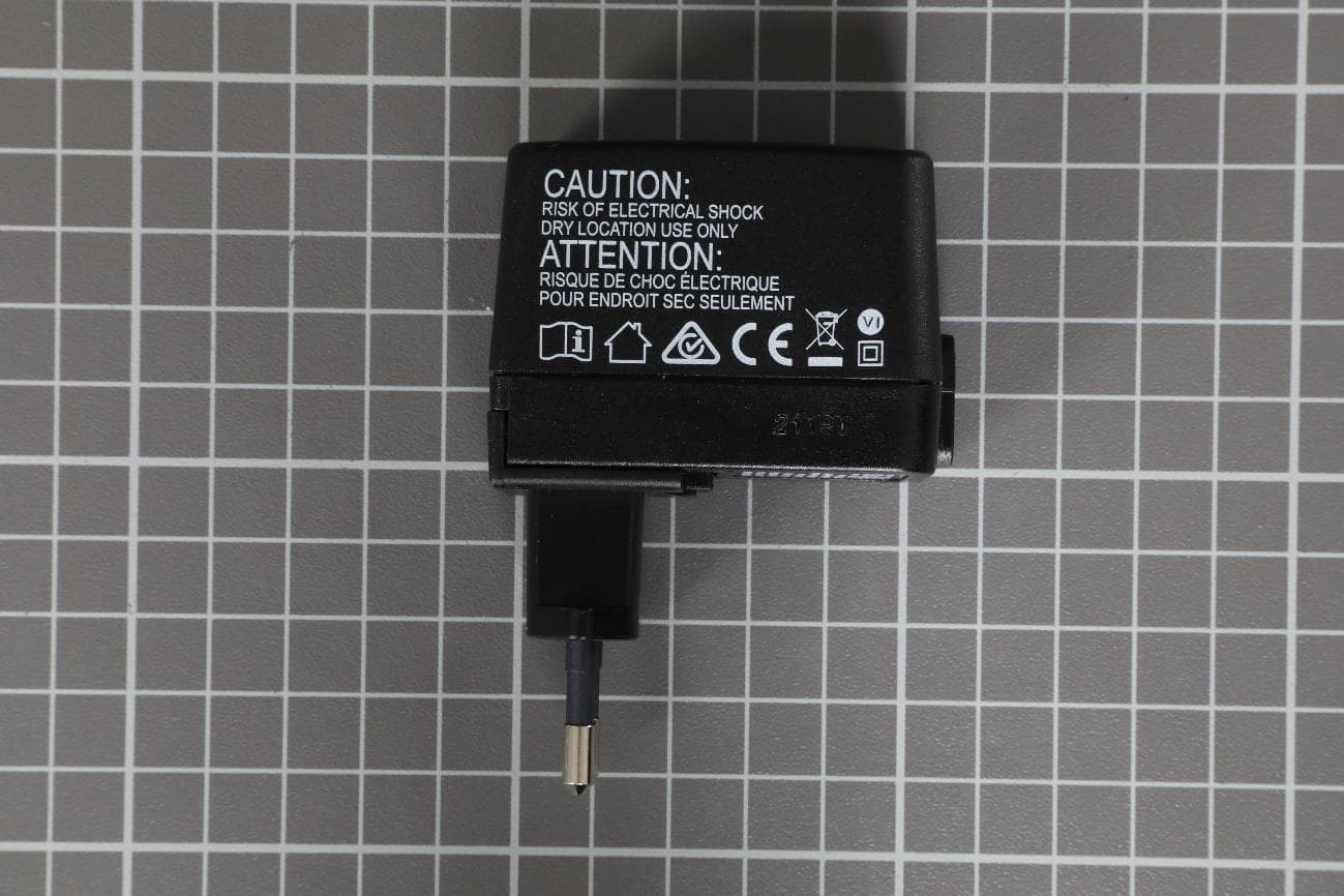
QLXKR0304
May 09, 2021Desktop KeyReader Plus
Equipment Class
DXX - Part 15 Low Power Communication Device Transmitter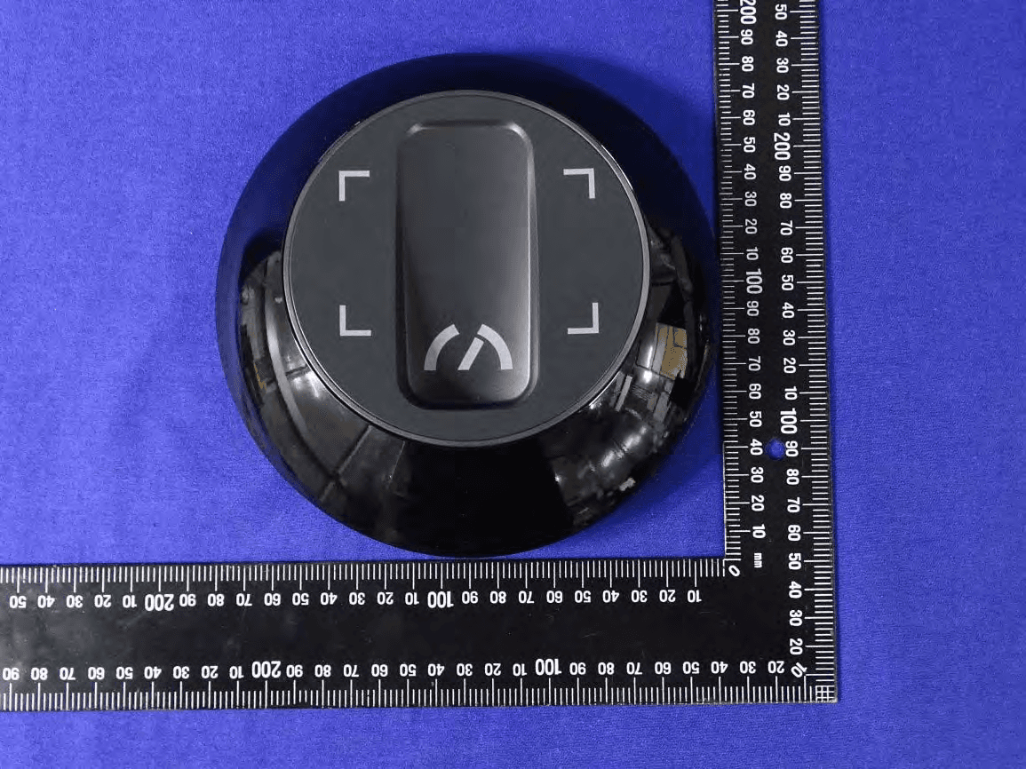
QLXKR0164
May 20, 2020Service Key Reader
Equipment Class
DCD - Part 15 Low Power Transmitter Below 1705 kHz
QLXCDL0236
Mar 05, 2020Central Door Lock
Equipment Class
DXX - Part 15 Low Power Communication Device Transmitter
QLXCDLOS
Mar 18, 2014Transceiver
Equipment Class
DXT - Part 15 Low Power Transceiver, Rx Verified