QLXKR0304Desktop KeyReader Plus
Tera Tron GmbH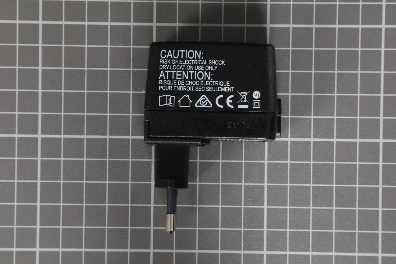
Click to zoom
Application Details
- Equipment Class
- DXX - Part 15 Low Power Communication Device Transmitter
- Date of Grant
- May 09, 2021
- Application Purpose
- Original Equipment
- Date of Application
- May 09, 2021
- Equipment Note
- Desktop KeyReader Plus
- Frequency Range
- 13.56000000 - 13.56000000
- Company
- Tera Tron GmbH
- Country
- Germany
Documents & Files
Document Text
Text extracted from the exhibit documents filed with the FCC. Open a document above to read the original.
Users Manual
Desktop KeyReader Plus Operating Manual Operating Manual Desktop KeyReader Plus ©TeraTron GmbH Page 1 of 12 Document Version 1.0 Date: February 25, 2021 Author: Marcel Mörchen DesktopKeyReaderPlus_EN.docx Desktop KeyReader Plus Desktop KeyReader Plus Operating Manual Operating Manual Desktop KeyReader Plus ©TeraTron GmbH Page 2 of 12 Document Version 1.0 Date: February 25, 2021 Author: Marcel Mörchen DesktopKeyReaderPlus_EN.docx Table of Contents 1. Introduction ..................................................................................................................................... 3 1.1. Setup ........................................................................................................................................ 3 1.2. Display and Control Elements ................................................................................................. 4 2. Mechanical Design........................................................................................................................... 5 3. Status LED Overview ........................................................................................................................ 6 4. Configuring Desktop KeyReader Plus .............................................................................................. 6 5. Operating Desktop KeyReader Plus ................................................................................................. 7 5.1. Reading the Vehicle Key .......................................................................................................... 7 5.2. Vehicle Key Data ...................................................................................................................... 8 6. Troubleshooting .............................................................................................................................. 9 7. Regulatory Notes ........................................................................................................................... 10 Desktop KeyReader Plus Operating Manual Operating Manual Desktop KeyReader Plus ©TeraTron GmbH Page 3 of 12 Document Version 1.0 Date: February 25, 2021 Author: Marcel Mörchen DesktopKeyReaderPlus_EN.docx 1. Introduction Desktop KeyReader Plus is a stationary device for reading out the vehicle data stored in the vehicle key. Once successfully read, the data is transmitted to a USB-connected PC. From there, the data is transmitted to a target system (KAI server). The USB connection also ensures the power supply. 1.1. Setup To run and configure Desktop KeyReader Plus on a PC, first install and launch the ITOOLS- USBTrayApp software. This tool communicates with Desktop KeyReader Plus, receives read-out key data, and sends configuration commands, e.g. to adjust the volume. This communication begins as soon as Desktop KeyReader Plus is connected. KAI server Desktop KeyReader Plus Desktop PC USB Figure 1: Typical system configuration Desktop KeyReader Plus Desktop PC LAN/WLAN KAI server USB Desktop KeyReader Plus Operating Manual Operating Manual Desktop KeyReader Plus ©TeraTron GmbH Page 4 of 12 Document Version 1.0 Date: February 25, 2021 Author: Marcel Mörchen DesktopKeyReaderPlus_EN.docx 1.2. Display and Control Elements Desktop KeyReader Plus features a white LED (status LED) on the front left and a multicolor LED (key LED) on the front right. The status LED indicates the current operating status: • Off (not connected) • Connected, but no communication established • Connected and communication established with ITOOLS-USBTrayApp (normal mode) • Connected and communication established with ITOOLS-USBTrayApp (VIN mode) The key LED indicates a key’s recognition and upload status. It also indicates the upgrade status when the device is undergoing an upgrade. A detailed description is provided in Section 3 Desktop KeyReader Plus Operating Manual Operating Manual Desktop KeyReader Plus ©TeraTron GmbH Page 5 of 12 Document Version 1.0 Date: February 25, 2021 Author: Marcel Mörchen DesktopKeyReaderPlus_EN.docx 2. Mechanical Design Figure 2: Top view 1) USB cable with type A plug connector 2) Round vehicle key tray 3) Status LED indicating operating mode(s) 4) Key LED indicating recognition/upload status or device upgrade status Figure 3: Rear view 1) Grommet for USB cable 2) Rubber plug 2 1 4 3 1 2 Desktop KeyReader Plus Operating Manual Operating Manual Desktop KeyReader Plus ©TeraTron GmbH Page 6 of 12 Document Version 1.0 Date: February 25, 2021 Author: Marcel Mörchen DesktopKeyReaderPlus_EN.docx 3. Status LED Overview Status LED (left LED): Off Solid white Fast blinking white Slow blinking white No USB connection to PC. USB cable is not plugged in. USB connection is OK. Communication with ITOOLS-USBTrayApp established successfully. USB connection is OK. Communication with ITOOLS-USBTrayApp could not be established. USB connection is OK. VIN mode is active. Key LED (right LED): Off Slow blinking green Solid green Rapid blinking yellow No key detected. Key data uploading. Key data successfully uploaded. Device is in upgrade mode. Device is receiving new firmware. 4. Configuring Desktop KeyReader Plus The ITOOLS-USBTrayApp software includes all drivers and configuration settings. Please follow the instructions in the ITOOLS-USBTrayApp manual. ITOOLS-USBTrayApp is a BMW application built for the BMW ISPI Next environment. The software distribution, registration and documentation are in compliance with established ISPI Next standards. Desktop KeyReader Plus Operating Manual Operating Manual Desktop KeyReader Plus ©TeraTron GmbH Page 7 of 12 Document Version 1.0 Date: February 25, 2021 Author: Marcel Mörchen DesktopKeyReaderPlus_EN.docx 5. Operating Desktop KeyReader Plus 5.1. Reading the Vehicle Key When the status LED is on, you are free to place a key on the Desktop KeyReader Plus tray. The entire key must fit within the tray and must be positioned flat. The direction the key is pointing is irrelevant (see ima…
Text truncated - open the document above for the full version.
External Photos
Germany · IBL-Lab GmbH · Heinrich-Hertz-Allee 7-10 · 66386 Sankt Ingbert · Tel: +49 6894 38938-0 · Fax: +49 6894 38938-99 1 / 5 Company Register: 105151, Amtsgericht Saarbrücken URL: www.ib-lenhardt.de · E-Mail: [email protected] Annex A External photographs of EUT part of / in addition to Test report no.: 19113662-17867 Tested by (name, function, signature) Karsten Geraldy Head of Laboratory RF signature Approved by (name, function, signature) Dr.-Ing. Harald Ansorge Managing Director signature Annex A of TR no.: 19113662-17867 2 / 5 IBL-Lab GmbH Photo No. 1 Photo No. 2 Annex A of TR no.: 19113662-17867 3 / 5 IBL-Lab GmbH Photo No. 3 Photo No. 4 Annex A of TR no.: 19113662-17867 4 / 5 IBL-Lab GmbH Photo No. 5 Annex A of TR no.: 19113662-17867 5 / 5 IBL-Lab GmbH Revision History -1 Initial Version End of Annex
Internal Photos
Germany · IBL-Lab GmbH · Heinrich-Hertz-Allee 7-10 · 66386 Sankt Ingbert · Tel: +49 6894 38938-0 · Fax: +49 6894 38938-99 1 / 5 Company Register: 105151, Amtsgericht Saarbrücken URL: www.ib-lenhardt.de · E-Mail: [email protected] Annex B Internal photographs of EUT (as provided by applicant) part of / in addition to Test report no.: 19113662-17867 Tested by (name, function, signature) Karsten Geraldy Head of Laboratory RF signature Approved by (name, function, signature) Dr.-Ing. Harald Ansorge Managing Director signature Annex B of TR no.: 19113662-17867 2 / 5 IBL-Lab GmbH Photo No. 1 Photo No. 2 Annex B of TR no.: 19113662-17867 3 / 5 IBL-Lab GmbH Photo No. 3 Photo No. 4 Annex B of TR no.: 19113662-17867 4 / 5 IBL-Lab GmbH Photo No. 5 Photo No. 6 Annex B of TR no.: 19113662-17867 5 / 5 IBL-Lab GmbH Revision History -1 Initial Version End of Annex
Test Report
Germany · IBL-Lab GmbH · Heinrich-Hertz-Allee 7-10 · 66386 Sankt Ingbert · Tel: +49 6894 38938-0 · Fax: +49 6894 38938-99 1 / 30 Company Register: 105151, Amtsgericht Saarbrücken URL: www.ib-lenhardt.de · E-Mail: [email protected] Test Report Test report no.: 19113662-17867-3 Date of issue: 2021-05-02 Test result: The test item - passed - and complies with below listed standards. Applicant TeraTron GmbH Manufacturer TeraTron GmbH Test Item KR0304 RF-Spectrum Testing according to: FCC 47 CFR Part 15 Radio Frequency Devices, Subpart C - §15.225 Operation within the band 13.110-14.010 MHz RSS-210 Licence-Exempt Radio Apparatus: Category I Equipment Tested by (name, function, signature) Karsten Geraldy Head of Laboratory RF signature Approved by (name, function, signature) Dr.-Ing. Harald Ansorge Managing Director signature TR no.: 19113662-17867-3 2021-05-02 2 / 30 IBL-Lab GmbH Applicant and Test item details Applicant TeraTron GmbH Martin-Siebert-Str. 5 51647, Gummersbach, Germany Manufacturer TeraTron GmbH Martin-Siebert-Str. 5 51647, Gummersbach, Germany Test item description Desktop KeyReader Plus Model/Type reference KR0304 FCC ID QLXKR0304 IC 4430A-KR0304 PMN Desktop KeyReader Plus HVIN KR0304 FVIN N/A HMN N/A Frequency 13.56 MHz Antenna Integrated PCB antenna Power supply 5.0 V DC via USB Connection from PC Temperature range 0 °C ± +45 °C Disclaimer and Notes The content of this rest report relates to the mentioned test sample(s) only. Without a written permit of IBL-Lab GmbH, this test report shall not be reproduced, except in full. The last valid version is available at TAMSys £ . Copyright : All rights reserved by IBL-Lab GmbH Within this test report, a ☒ point / ☐ comma is used as a decimal separator. If otherwise, a detailed note is added adjected to its use. IBL-Lab GmbH does not take test samples. The sample used for testing is provided by the applicant. Decision rule: Binary Statement for Simple Acceptance Rule according ILAC-G8:09/2019 TR no.: 19113662-17867-3 2021-05-02 3 / 30 IBL-Lab GmbH 1 TABLE OF CONTENTS 1 TABLE OF CONTENTS ......................................................................................................................... 3 2 GENERAL INFORMATION ................................................................................................................... 4 2.1 Administrative details .......................................................................................................................... 4 2.2 Possible test case verdicts ................................................................................................................. 4 2.3 Observations ....................................................................................................................................... 4 2.4 Opinions and interpretations ............................................................................................................... 4 2.5 Revision History .................................................................................................................................. 5 2.6 Further documents .............................................................................................................................. 5 3 ENVIRONMENTAL & TEST CONDITIONS........................................................................................... 6 3.1 Environmental conditions ................................................................................................................... 6 3.2 Normal and extreme test conditions ................................................................................................... 6 4 TEST STANDARDS AND REFERENCES ............................................................................................ 6 5 EQUIPMENT UNDER TEST (EUT) ....................................................................................................... 7 5.1 Product description ............................................................................................................................. 7 5.2 Description of test item ....................................................................................................................... 7 5.3 Technical data of test item .................................................................................................................. 7 5.4 Additional information ......................................................................................................................... 7 6 Test Setup Description........................................................................................................................... 8 6.1 Semi Anechoic Chamber with Ground Plane ..................................................................................... 9 6.2 AC conducted ................................................................................................................................... 11 6.3 Frequency error ................................................................................................................................ 12 7 Measurement procedures .................................................................................................................... 13 7.1 Radiated spurious emissions from 9 kHz to 30 MHz ........................................................................ 13 7.2 Radiated spurious emissions from 30 MHz to 1 GHz ....................................................................... 14 8 SUMMARY OF TEST RESULTS ......................................................................................................... 15 9 TEST RESULTS .................................................................................................................................. 16 9.1 Field strength of emissions (transmitter spectrum mask) ................................................................. 16 9.2 Field strength of emissions (spurious and harmonics) .........…
Text truncated - open the document above for the full version.
Test Setup Photos
Germany · IBL-Lab GmbH · Heinrich-Hertz-Allee 7-10 · 66386 Sankt Ingbert · Tel: +49 6894 38938-0 · Fax: +49 6894 38938-99 1 / 5 Company Register: 105151, Amtsgericht Saarbrücken URL: www.ib-lenhardt.de · E-Mail: [email protected] Annex C Photographs of test setup for FCC / IC part of / in addition to Test report no.: 19113662-17867 Tested by (name, function, signature) Karsten Geraldy Head of Laboratory RF signature Approved by (name, function, signature) Dr.-Ing. Harald Ansorge Managing Director signature Annex C of TR no.: 19113662-17867 2 / 5 IBL-Lab GmbH Photo No. 1 Photo No. 2 Annex C of TR no.: 19113662-17867 3 / 5 IBL-Lab GmbH Photo No. 3 Photo No. 4 Annex C of TR no.: 19113662-17867 4 / 5 IBL-Lab GmbH Photo No. 5 Annex C of TR no.: 19113662-17867 5 / 5 IBL-Lab GmbH Revision History -1 Initial Version End of Annex
Contact Information
Applicant
Rainer Helberg(Mr.)
Test Firm
IBL-Lab GmbHKarsten Geraldy
[email protected]+ 49 6894 389 3868
Technical Specifications
| # | Rule Parts | Frequency Range | Power Output |
|---|---|---|---|
| 1 | 15C | 13.56 MHz - 13.56 MHz | - |
Other Applications from Tera Tron GmbH
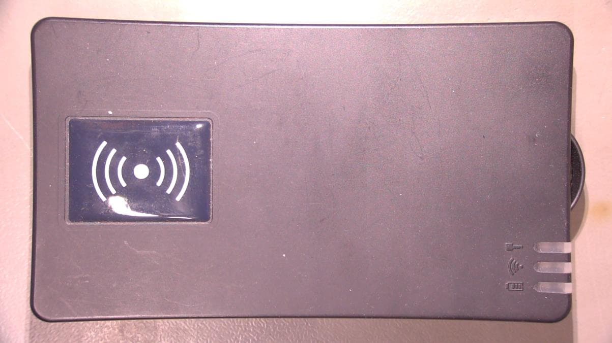
QLXKRP0320
Dec 03, 2023Mobile Vehicle Key Reader
Equipment Class
DXX - Part 15 Low Power Communication Device Transmitter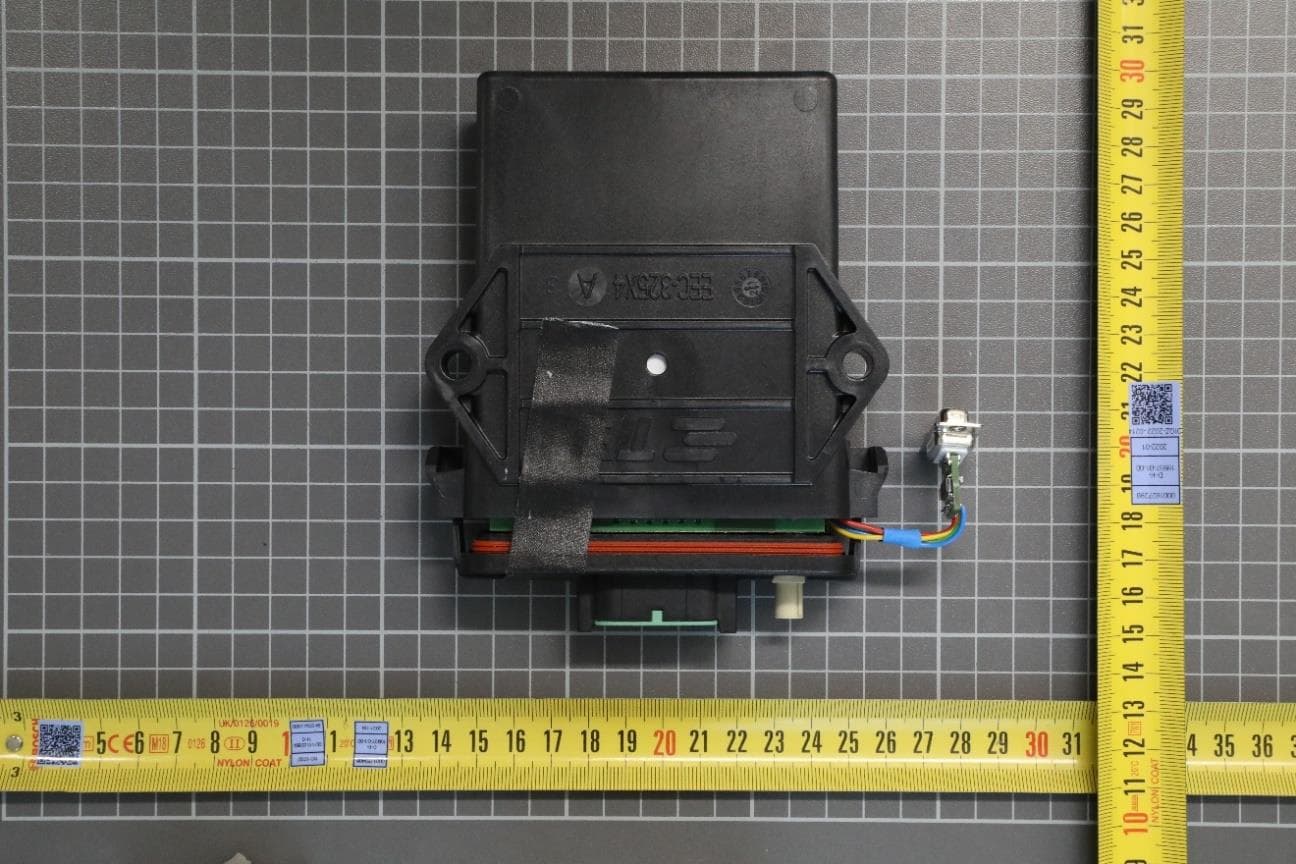
QLXBSS255R
Jun 05, 2023Protective Field Reader
Equipment Class
DCD - Part 15 Low Power Transmitter Below 1705 kHz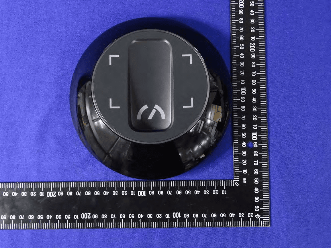
QLXKR0164
May 20, 2020Service Key Reader
Equipment Class
DCD - Part 15 Low Power Transmitter Below 1705 kHz
QLXCDL0236
Mar 05, 2020Central Door Lock
Equipment Class
DXX - Part 15 Low Power Communication Device Transmitter
QLXCDLOS
Mar 18, 2014Transceiver
Equipment Class
DXT - Part 15 Low Power Transceiver, Rx Verified