QQ715920ITAG
Shenzhen Ronghua Electronic Co. Ltd.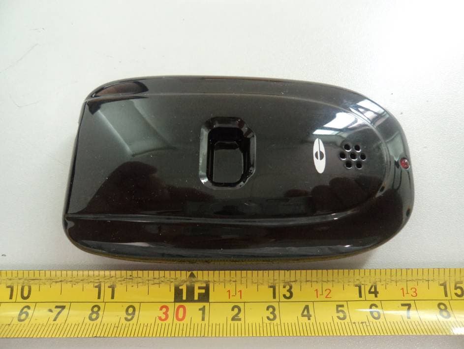
Click to zoom
Application Details
- Equipment Class
- DSR - Part 15 Remote Control/Security Device Transceiver
- Date of Grant
- Mar 16, 2012
- Application Purpose
- Original Equipment
- Date of Application
- Mar 16, 2012
- Equipment Note
- ITAG
- Frequency Range
- 434.06000000 - 434.06000000
- Country
- China
Documents & Files
Document Text
Text extracted from the exhibit documents filed with the FCC. Open a document above to read the original.
Users Manual
The 15920 is a new kind of removal alert tag working with remote control (EG-RC600) and remote alarm receiver (15901R). It is the devices especially designed for protecting valuable electronic product such as camera、mobile phone、MP3 etc. Installation procedures 1: fix the 15920 on the table board with screws 2: rip the sheet off the protection block, and cling the glaze of the merchandise to the protection block firmly 3: insert the pin of the tie into the 15920, then the 15920 will twinkle for six times and give of two sounds and at last, the commodity is under protection. Attention: 1 the glaze should be flatness, free of moisture and dust 2 the ties shouldn’t be elongated and bumped in excess Alarm qualification (under ward mode): 1 disconnection: if the tie is cut, or the pin is dragged out of the jack or the goods is ripped off the protection block unauthorized, the 15920 will give of alarm (alarm mode) and send its own ID number to the 15901R to make it alarm for the administrators to alert. 2 track the EAS: if the 15920 in the ward mode is close to the electronic alert system, the 15920 will give of alarm (alarm mode) and send its own ID number to the 15901R to make it alarm for the administrators to alert. Payment function: If anyone wants to buy the commodity under protection, press the reset bottom of the remote controller, and then rip the goods off the protection block or pull the pin out of the jack of the 15920 in 10 seconds, this will avoid the 15920’s alarm. The 15920 will then detect the states of the switch and the jack to decide to go into ward mode or idle mode. Disarm alarm: When the 15920 alarms, press the reset bottom of the remote controller, the 15920 will stop alarming and send signal to disarm the 15901R. Attentions: disarm the alarm of 15920 as soon as possible; when the alarm is undertone, replace the cell in it. For reuse: 1 Make sure the switches and the ties are in working order 2 make sure the glutinosity of the bottom of the protection block is good for fixing. 3 make sure the alarm of the 15920 is normal For replace the cell: When the alarm of the 15920 is undertone or can’t be stopped by EG-RC600, or the 15920 can’t make the 15901R alarm, please replace the cell in it: 1 open the crust of the 15920 and replace the cell in it 2 make sure the 15920 work normally and can make the 15901R alarm 3 envelop the crust of the 15920 This device complies with part 15 of the FCC Rules. Operation is subject to the following two conditions: (1) This device may not cause harmful interference, and (2) this device must accept any interference received, including interference that may cause undesired operation. Any Changes or modifications not expressly approved by the party responsible for compliance could void the user's authority to operate the equipment.
Block Diagram
FSK Signal (MAX 8dbm) MCU Wireless Module Alarm Key RF Receive Circuit 8.2M antenna 434±0.1MHz antenna 8MHz Oscillator 10MHz Oscillator
External Photos
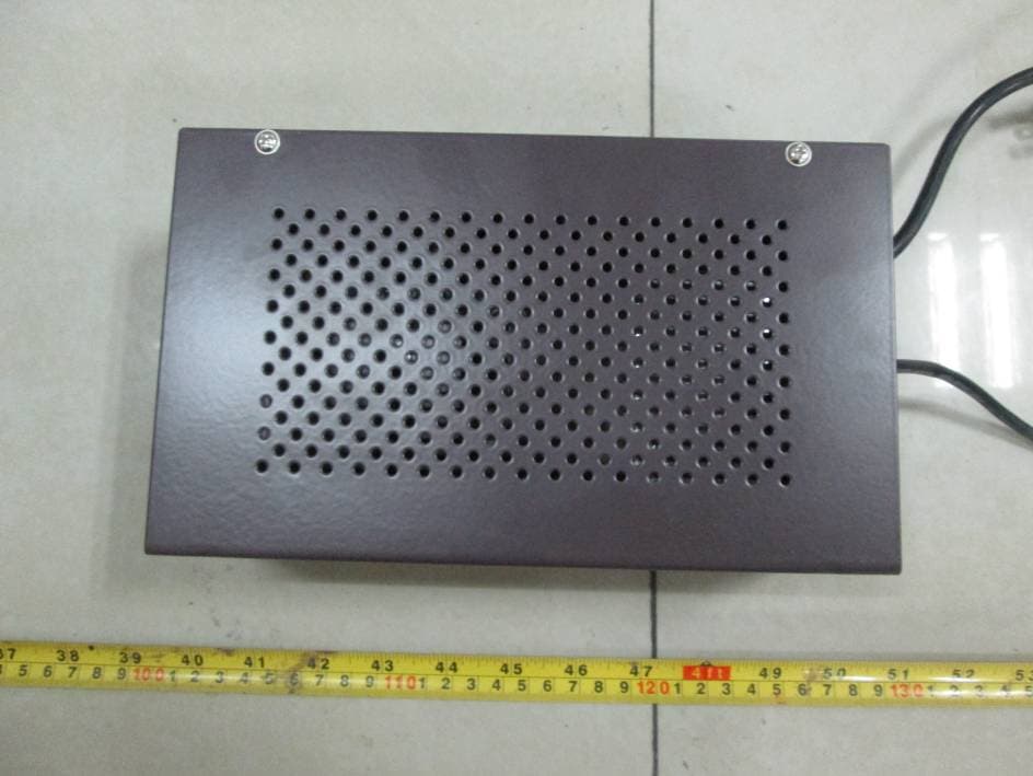
EXHIBIT B - EUT EXTERNAL PHOTOGRAPHS EUT– All View EUT– Top View EUT– Bottom View EUT– Side View
ID Label/Location Info
EXHIBIT A - FCC ID LABELING AND LOCATION FCC ID Label FCC ID Label Location
Internal Photos
EXHIBIT C - EUT INTERNAL PHOTOGRAPHS EUT - Cover off View 1 EUT - Cover off View 2 EUT - Main Board Top View EUT - Main Board Bottom View Antenna
Operational Description
Circuit description The 15920 is a new kind of removal alert tag(RAT) with remote control、 wireless communication、alarm and signal look-over functions which consists of receiving circuit(8.2MHz receive antenna) 、 wireless transition circuit(433MHz carry frequency, 10MHz oscillator) 、 main control unit(8MHz oscillator) 、 alarm circuit and detect idle time circuit(The key). It is the devices especially designed for protecting valuable electronic product such as camera、mobile phone、MP3 etc. If the key is closed, the 15920 will twinkle for six times and give of two sounds and come to sleep. That is the ward mode. In this mode, if anyone presses the reset bottom of the remote controller, the 15920 won’t alarm if you loosen the key in 10 seconds, which is the payment mode, avoiding the 15920’s alarm. The 15920 will then detect the states of the key to decide to go into ward mode or idle mode. In the ward mode, if the key is loosened, the 15920 will give of alarm (alarm mode) and send its own ID number to the 15901R to make it alarm for the administrators to alert unless the signal of the remote controller received. In the alarm mode, if the 15920receives the remote controller signal, it will stop alarming and send signal to disarm the 15901R.
Schematics
2008.11.22 Hope Microelectronics Co., Ltd Ô¬º£Åô <Checked By> <QC By> <Released By> <Checked Date> <QC Date> <Release Date> <Code> B <Scale> 1 1 REV: SIZE: CODE: DRAWN: DATED: DATED: CHECKED: QUALITY CONTROL: DATED: DATED: RELEASED: COMPANY: TITLE: DRAWING NO: SHEET: OF SCALE: REVISION RECORD APPROVED: ECO NO: A B D DATE: 1 2 3 4 5 6 D C A B C RFM02-315S/434S/869S/915S schematic V1.0 L1 L2 L3 L4 C2 C4 C5 C7 Operation Frequency Band 315MHZ 434MHZ 869MHZ 915MHZ 27nH 27nH 33PF 5.6pF 5.6pF 3.9pF 220nH 1pF 3.9pF 3.9pF 47pF 8.2nH 12nH 10nH 47nH 47nH 10nH 12nH 8.2nH 3.9pF 3.9pF 47pF 1pF 1 SDI 2 SCK 3 NSEL 4 CLK 5 XTL 6 VSS_D 7 VSS_A 8 VSS_RF 9 MOD 10 RFN 11 RFP 12 NIRQ 13 VDD_RF 14 VDD_A 15 VDD_D 16 FSK U1 RF02 L1 C2 C3 10nF C4 C5 L2 L3 L4 X1 10M 0-10MPPM C7 ANT SDI SCK NSEL NSEL NIRQ FSK +5V +5V GND GND GND C I HOPERF E E L C T R O N REV: APPROVED: REV: TITLE: COMPANY: APPROVAL: DATED: DATED: DRAWN: DATE: REVISION RECORD SHEET: 1 OF 1 Hope Microelectronics Co., Ltd SunBo 1.0 Mar 25,08 434MHz L1 C1 C2 RFM01-315D/434D/869D/915D schematic 869MHz 915MHz 39nH 6pF 6pF 18nH 2.2pF 2.2pF 18nH 2.2pF 2.2pF SunBo Mar 25,08 Operation Frequency Band Description Summary of Revision 1.0 ³õʼ°æ±¾ SunBo Mar 25,08 315MHz 56nH 6pF 6pF C2 C3 0.1uF C1 C4 4.7nF 1 2 X1 +/-8PPM 10MHz 1 SDI 2 SCK 3 NSEL 4 FFIT/SDO 5 NIRQ 6 DATA/NFFS 7 DCLK/CFIL/FFIT 8 CLK 9 XTL 10 NRES 11 VSS 12 IN2 13 IN1 14 VDD 15 ARSSI 16 VDI U1 RF01 L1 SDI SCK NSEL SDO VCC ANT VCC NIRQ DCLK CLK NRES VDI
Schematics
version A scale 1:1 Tailor 1st Total 1 Audit SRH.15920.DL01 Alter Mark Alter Number signature Date Ratifica tion 15920 Schematics Shenzhen ronghua electronic co., Ltd
Test Report
Note: This test report is prepared for the customer shown above and for the equipment described herein. It may not be duplicated or used in part without prior written consent from Bay Area Compliance Laboratories Corp. This report must not be used by the customer to claim product certification, approval, or endorsement by NVLAP*, or any agency of the Federal Government. * This report contains data that are not covered by the NVLAP accreditation and are marked with an asterisk “★” (Rev.2) FCC PART 15.231 TEST REPORT For Shenzhen Ronghua Electronic Co., Ltd. Building 1, Quanxinyuan Industrial Park, Huafan Road, Dalang Sub-district, Longhua, Bao’an District, Shenzhen, Guangdong, China FCC ID: QQ715920 Report Type: Original Report Product Type: Removal Alert Tag (RAT) Test Engineer: Back Huang Report Number: RSZ110706003-00 Report Date: 2012-03-16 Reviewed By: Merry Zhao EMC Engineer Test Laboratory: Bay Area Compliance Laboratories Corp. (Shenzhen) 6/F, the 3rd Phase of WanLi Industrial Building, ShiHua Road, FuTian Free Trade Zone Shenzhen, Guangdong, China Tel: +86-755-33320018 Fax: +86-755-33320008 www.baclcorp.com.cn Bay Area Compliance Laboratories Corp. (Shenzhen) Report No.: RSZ110706003-00 FCC Part 15.231 Page 2 of 19 TABLE OF CONTENTS GENERAL INFORMATION.......................................................................................................................................3 PRODUCT DESCRIPTION FOR EQUIPMENT UNDER TEST (EUT) ....................................................................................3 OBJECTIVE...................................................................................................................................................................3 RELATED SUBMITTAL(S)/GRANT(S).............................................................................................................................3 TEST METHODOLOGY..................................................................................................................................................3 TEST FACILITY.............................................................................................................................................................3 SYSTEM TEST CONFIGURATION ..........................................................................................................................5 JUSTIFICATION.............................................................................................................................................................5 SPECIAL ACCESSORIES.................................................................................................................................................5 EQUIPMENT MODIFICATIONS.......................................................................................................................................5 CONFIGURATION OF TEST SETUP.................................................................................................................................5 BLOCK DIAGRAM OF TEST SETUP................................................................................................................................5 SUMMARY OF TEST RESULTS...............................................................................................................................6 FCC §15.203 - ANTENNA REQUIREMENT.............................................................................................................7 APPLICABLE STANDARD..............................................................................................................................................7 FCC §15.205, §15.209, §15.231 (B), - RADIATED EMISSIONS ..............................................................................8 MEASUREMENT UNCERTAINTY....................................................................................................................................8 EUT SETUP..................................................................................................................................................................8 EMI TEST RECEIVER SETUP.........................................................................................................................................9 TEST PROCEDURE........................................................................................................................................................9 APPLICABLE STANDARD..............................................................................................................................................9 CORRECTED AMPLITUDE & MARGIN CALCULATION.................................................................................................10 TEST EQUIPMENT LIST AND DETAILS.........................................................................................................................10 TEST RESULTS SUMMARY..........................................................................................................................................10 TEST DATA................................................................................................................................................................10 FCC §15.231(C) – 20 DB BANDWIDTH TESTING ................................................................................................12 REQUIREMENT...........................................................................................................................................................12 TEST EQUIPMENT LIST AND DETAILS.........................................................................................................................12 TEST PROCEDURE......................................................................................................................................................12 TEST DATA...................................................................................................................................…
Text truncated - open the document above for the full version.
Test Setup Photos
EXHIBIT D - TEST SETUP PHOTOGRAPHS Radiated Emission Test View (30 MHz-1000 MHz) Radiated Emission Test View (1-5 GHz)
Contact Information
Applicant
Guixing Chang(Engineer)
Test Firm
Bay Area Compliance Laboratory Corp. (Shenzhen)John Chan
Technical Specifications
| # | Rule Parts | Frequency Range | Power Output |
|---|---|---|---|
| 1 | 15.231 | 434.06 MHz - 434.06 MHz | - |
Other Applications from Shenzhen Ronghua Electronic Co. Ltd.
QQ7EGUARD7600
Mar 13, 2015Commodity Protector
Equipment Class
DXX - Part 15 Low Power Communication Device Transmitter
QQ7EGUARDRC900N
Mar 15, 2011Remote controller
Equipment Class
DXX - Part 15 Low Power Communication Device Transmitter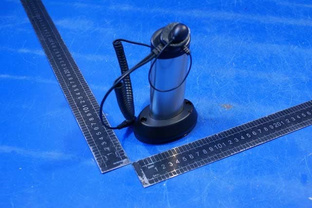
QQ7EGUARD15921N
Nov 29, 2010Removal Alert Tag
Equipment Class
DSR - Part 15 Remote Control/Security Device Transceiver
QQ7EGUARDEG3388
Jun 21, 2010Electronic Article Surveillance
Equipment Class
FAP - Part 15 Anti-Pilferage Device
QQ7EGUARDEAS02
May 19, 2003Swept Frequency Anti-pilferage Device
Equipment Class
FAP - Part 15 Anti-Pilferage Device