QQ7EGUARDEG3388Electronic Article Surveillance
Shenzhen Ronghua Electronic Co. Ltd.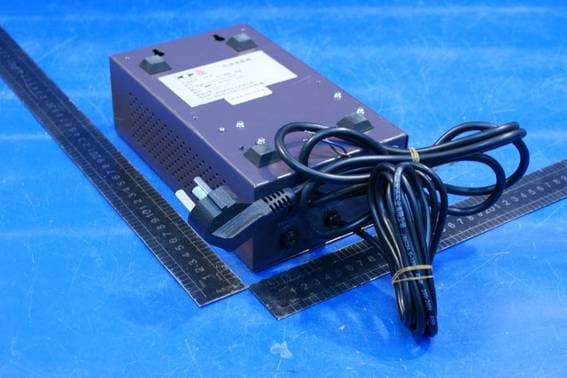
Click to zoom
Application Details
- Equipment Class
- FAP - Part 15 Anti-Pilferage Device
- Date of Grant
- Jun 21, 2010
- Application Purpose
- Original Equipment
- Date of Application
- Jun 21, 2010
- Equipment Note
- Electronic Article Surveillance
- Frequency Range
- 7.52000000 - 8.20000000
- Country
- China
Documents & Files
Document Text
Text extracted from the exhibit documents filed with the FCC. Open a document above to read the original.
Users Manual
Installation Manual for EG2233/EG3333/EG8406/EG3355/EG3388 RF EAS Systems • DSP system with proprietary software incorporating RF/ADD. • EG2233 classic. EG3333 ABS, EG8404 chrome and ABS, EG3355/3388 acrylic • Automatic analysis of noise and interference ensuring high pick rate and fast response time. • Digital system with auto-testing mode to ease tuning and installation. • Environmental friendly with low power usage. Diaward Electronic Security Systems Ltd. 15 th Floor, Fung House 19-20 Connaught Road Central Hong Kong R T PROJECT-1 A B Simplify Installation and Set-up Procedures (Tx2300 Transmitter and Rx4300 Receiver) Detection distance Distance Labels/tags Suggested Maximum 40×40mm labels 1.0m 1.2m Tags(Q≥220) 1.6m 1.8m Transmitter Antenna Tx 2300 (Refer to figure 5) Normally no tuning required. Technical Data: Operating voltage....... DC 24V Operating current....... < 450mA Fuse........................ 250V, 500mA Sweeping frequencies........ 7.6~8.2MHz Modulation frequency..180Hz, 172Hz, 160Hz or 150Hz (factory setting at 180Hz) Adjusting Modulation Frequency The modulation frequency is preset at the factory at 180Hz. Adjusting the setting at JP5, JP6, JP7 and JP8 will change the modulation frequency. Disconnected Connected 180Hz JP5, JP6, JP8 JP7 172Hz JP5, JP7, JP8 JP6 160Hz JP6, JP7, JP8 JP5 150Hz JP5, JP6, JP7 JP8 For systems to operate, the Modulation Frequency of the Tx and Rx must be the same. Multiple connections Non-synchronization If there are two or more groups of antennae which are 10m away from each other, and synchronization is not suitable, it is necessary to change the modulation frequency of one group from another to avoid interference between systems, i.e. one set of transmitters at 180Hz and while another set at 160Hz(or 150Hz or 172Hz). For example, in figure 1 and 4 if the two sets of systems are over 10m apart, setting two different modulation frequency for the two groups would be sufficient. However, for the set up in figure 2 and 3 , synchronization would be necessary (see section on Synchronization below). PROJECT-2 RRTTRR AB RT PROJECT-3 TR Multiple connections R T RT PROJECT-4 TR ELEVATOR Figure 1 Figure 2 Figure 3 Figure 4 Synchronization T2300 Slave T2300 Master Sweep freq. tuning Put EAS detector above transmitter, press “power” to detect: Fc: read 7.6~8.2MHz (VR15 for tuning); Fs: should read 180Hz when JP7 is connected; Δ:should read 1000±50KHz (VR14 for tuning). Receiver antenna Rx 4300(Refer to figure 6) Technical Data: Operating voltage................. DC 24V Operating current, stand-by...... < 300mA Operating current, operating..... < 400mA Fuse................................. 250V, 500mA Slide switches setting RF Labels and Hard Tags Selector Labels and Hard tags (factory setting) Hard tags only SW1-1 ON OFF Modulation Frequency 180Hz(factory setting) 172Hz 160Hz 150Hz SW1-2 ON On OFF OFF SW1-3 ON OFF ON OFF The modulation frequency in the Receiver Antenna must be the same as that in the Transmitter Antenna. Sensitivity Level Highest (factory setting) High Medium Low SW1-4 ON OFF ON OFF SW1-5 ON ON OFF OFF Detecting Moving and Stationery tags Detect both moving and stationery tags Detect moving tags only P4 P3 P4 P3 P3 JP2, JP3 in 1 & 2 position respectively (factory setting). Change slave setting in JP2, JP3 to 2 & 3 position Connect to another slave via P3. Connect to another slave via P3. (factory setting) SW1-6 ON OFF Note: once changes are made to either Tx Board or Rx Board, must press “RESET1” button on the Rx Board so that the systems will reboot itself. Noise signal tuning The light DS1, DS2 and DS3 indicate the conditions of the operation: i. If they do not lit up, this means perfect condition (no noise). ii. If only DS1 lit up, the condition is good. iii. If both DS1 and DS2 lit up, the condition is fair and the system can still operate effectively. iv. If all DS1, DS2 and DS3 lit up, there is much interference and will need to identify source of interference in order to find a viable solution. Timing of Alarm and Warning Light Adjust VR2 (clockwise to extend, anti-clockwise to reduce) for alarm and light on time varying 1~4 seconds. JP3 1&2 Alarm and light on/off simultaneously JP3 2&3 Light will remain on for 2~3 seconds after alarm Figure 5 ~T2300 Transmitter Figure 6 ~R4300 Receiver P6, Output +24VDC P5, Antenna connector P1, Input +24VDC JP8, JP5, JP6 and JP7 modulation freq. setting VR15,Center Frequency Tuning VR14, Sweep freq. Tuning Trouble shooting – High Interference P4, Antenna Connector P1, Input +24VDC VR1, Noise signal tuning VR4, Alarm volume tuning SW1, slide switches RESET JP3 Alarm and light, on/off timing DS1~DS3 Noise condition Buzzer socket Warning light socket VR2, Timing of Alarm and Warning Light If there were high interference, the system will shut itself off to avoid false alarm. To ensure the system will operate well, must try and eliminate obvious cause of interference. Then, follow the below instructions:- 1. In Tx, adjust VR14 until Sw reads 700 ~ 750. 2. In Rx, change jumper in JP1, moving one slot to the right i.e. from position 1/2 to 2/3. This is the case when there is high noise interference and detection distance is more than 1.5m. 3. In Rx, change jumper in JP2, moving one slot left i.e. from position 2/3 to ½. This is to eliminate the self-locking function at high noise interference. 4. In Rx, adjust VR1 until only DS1 light flashes. 5. In Rx, select SW1-4 to ON and SW1-5 to OFF. 6. Press RESET. If there is large metal objects close-by, may see if grounding it to the Rx antenna base labeled GND at P1 (connecting with wire) will improve interference. If no improvement, remove this grounding. The above adjustment is only suitable for hard tags use only and not for labels. The parameters for labels are weaker thus with the above adjustments, unless the labels are very made, detection would be poor. Attention! The users manual or instruction manual for an intentional or unintentional radiator shal…
Text truncated - open the document above for the full version.
Cover Letter(s)
Please address following issues. Q#1: According to the user manual, this device is formed with a TX 2300 and RX 4300 which does not agree with TX2200 and RX4200 as indicated in the operational description. Please address. A#1: the file was updated. Q#2: User manual should include 15.21 statements. Please update. A#2: the file was updated. Q#3: Please provide additional photo by remove the metal case from the receiving board in page 2 of the internal photos. A#3: the internal photo was updated. Q#4: User manual page 2 indicated that the fundamental frequency is 8.1MHz+/-0.5. And the fundamental frequency measured as documented in the test report is 8.419MHz which are more than 3MHz deviation than user manual mentioned. Please address. A#4: the User manual was updated. Q#5: Please update label format by adding 15.19 statements since the EUT is larger enough. A#5: the file was updated. Q#6: Page 2 of test report indicated that 15.247 is followed which should be typo, please update. A#6: the test report was updated. Q#7: As indicated in page 2 of the user manual, this device has 4 modulation frequencies: 180Hz, 172Hz, 160Hz and 150Hz. Which one was investigated? A#7: the test report was updated. Refer to page 8 of test report. Q#8: The test setup description in page 10 and page 17 of test report by placing EUT in the 80cm high table for test which does not suit for this device. The setting should follow floor-standing. Please update. A#8: the test report was updated. Q#9: The field strength of emissions outside of the band 1.705-10.0 MHz shall not exceed the general radiated emission limits in Section 15.209. Moreover, the limit is based on average detector. Please update the limit as documented in page 18 accordingly. A#9: manufacturer was change the sweep frequency range, the test report, user manual and operational description were updated.
External Photos
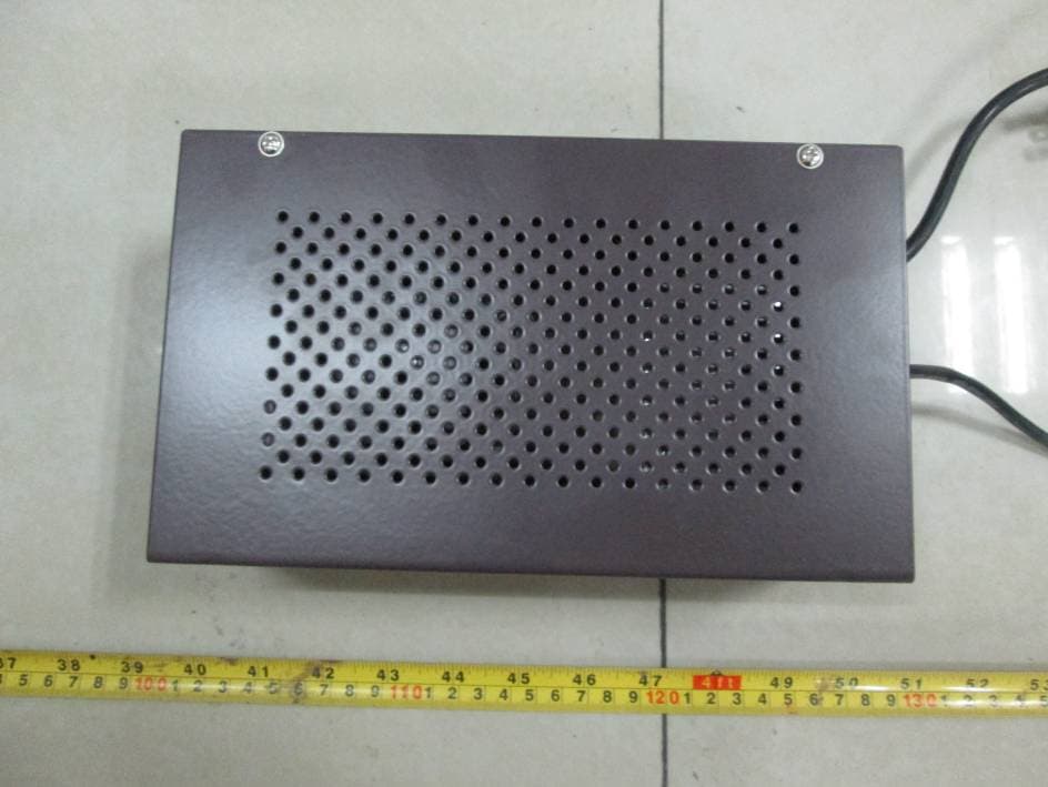
Photo 1 Appearance of EUT Photo 2 Appearance of EUT (Antenna) Photo 3 Appearance of EUT (Switching power supply) Photo 4 Appearance of EUT (Switching power supply)
ID Label/Location Info
ELECTRONIC ARTICLESURVEILLANCE SYSTEMS MFD : MADE IN CHINA PRODUCT MODEL : E G3388 PART NO . : T 2300 SERIAL NO. : RATING : 24VDC 400mA CENTER FREQUENCY : 8 . 2 MHz 0197 FCC ID:QQ7EGUARDEG3388 This device complies with Part 15 of the FCC Rules. Operation is subject to the following two conditions: (1) this device may not cause harmful interference, and (2) this device must accept any interference received,including interference that may cause undesired operation. This device complies with Part 15 of the FCC Rules. Operation is subject to the following two conditions: (1) this device may not cause harmful interference, and (2) this device must accept any interference received,including interference that may cause undesired operation. FCC ID:QQ7EGUARDEG3388 0197 CENTER FREQUENCY : 8 . 2 MHz 24VDC 450mA RATING : SERIAL NO. : PART NO . : R 4300 G3388 : E PRODUCT MODEL MFD : MADE IN CHINA SURVEILLANCE SYSTEMSELECTRONIC ARTICLE PDF 文件使用 "pdfFactory Pro" 试用版本创建 www.fineprint.cn This device complies with Part 15 of the FCC Rules. Operation is subject to the following two conditions: (1) this device may not cause harmful interference, and (2) this device must accept any interference received,including interference that may cause undesired operation. FCC ID:QQ7EGUARDEG3388 0197 CENTER FREQUENCY :8.2MHz 24VDC 400mA RATING : SERIAL NO. : PART NO. :T2300 G3388: EPRODUCT MODEL MFD :MADE IN CHINA SURVEILLANCE SYSTEMS ELECTRONIC ARTICLE PDF 文件使用 "pdfFactory Pro" 试用版本创建 www.fineprint.cn
Internal Photos
Photo 1 Inside of EUT (Antenna) Photo 2 Inside of EUT (Antenna) Photo 3 Inside of EUT (Antenna) Photo 4 Inside of EUT (Antenna) Photo 5 Inside of EUT (Antenna) Photo 6 Inside of EUT (Antenna) Photo 7 Inside of EUT (Antenna) Photo 8 Inside of EUT (Antenna) Photo 9 Inside of EUT (Switching power supply) Photo 10 Inside of EUT (Switching power supply) Photo 11 Inside of EUT (Switching power supply)
Test Report
Page 1/23 FCC TEST REPORT For Electronic Article Surveillance Model Number: EG3388 FCC ID: QQ7EGUARDEG3388 Report Number : WT098001579 Test Laboratory : Shenzhen Academy of Metrology and Quality Inspection National Testing Center for Digital Electronic Products Site Location : Bldg. Metrology and Quality Inspection, Longzhu Road, Shenzhen, Guangdong, China Tel : 0086-755-26941599 Fax : 0086-755-26941545 Web : www.smq.com.cn Report No.:WT098001579 Page 2 of 23 Test report declaration Applicant : Shenzhen ronghua electric Co., Ltd Address : 3rd floor, 524th building, Bagualing, Futian, Shenzhen Manufacturer : Shenzhen ronghua electric Co., Ltd Address : 3rd floor, 524th building, Bagualing, Futian, Shenzhen EUT Description : Electronic Article Surveillance Model No : EG3388 FCC ID : QQ7EGUARDEG3388 Test Standards: FCC Part 15 15.31,15.35,15.203,15.205,15.207 15.209, 15.223 The EUT described above is tested by Shenzhen Academy of Metrology and Quality Inspection EMC Laboratory to determine the maximum emissions from the EUT. Shenzhen Academy of Metrology and Quality Inspection EMC Laboratory is assumed full responsibility for the accuracy of the test results. The test data, data evaluation, test procedures, and equipment configurations shown in this report were made in accordance with the procedures given in ANSI C63.4 (2003) and the energy emitted by the sample EUT tested as described in this report is in compliance with FCC Rules Part 15.203, 15.205, 15.207, 15.209 and15.223. The test report is valid for above tested sample only and shall not be reproduced in part without written approval of the laboratory. Project Engineer: Date: Jan.13,2010 (Ryan Chen) Checked by: Date: Jan.13,2010 (Dewelly Yang) Approved by: Date: Jan.13,2010 (Peter Lin) Report No.:WT098001579 Page 3 of 23 TABLE OF CONTENTS TEST REPORT DECLARATION........................................................................................................2 1. TEST RESULTS SUMMARY...................................................................................................4 2. GENERAL INFORMATION......................................................................................................5 2.1. Report information..........................................................................................................5 2.2. Laboratory Accreditation and Relationship to Customer.........................................5 2.3. Measurement Uncertainty.............................................................................................6 3. PRODUCT DESCRIPTION.......................................................................................................7 3.1. EUT Description..............................................................................................................7 3.2. Related Submittal(s) / Grant (s)...................................................................................7 3.3. Block Diagram of EUT Configuration..........................................................................7 3.4. Operating Condition of EUT..........................................................................................8 3.5. Support Equipment List.................................................................................................8 3.6. Test Conditions...............................................................................................................8 3.7. Special Accessories.......................................................................................................8 3.8. Equipment Modifications...............................................................................................8 4. TEST EQUIPMENT USED........................................................................................................9 5. CONDUCTED DISTURBANCE TEST..................................................................................10 5.1. Test Standard and Limit..............................................................................................10 5.2. Test Procedure.............................................................................................................10 5.3. Test Arrangement.........................................................................................................10 5.4. Test Data.......................................................................................................................10 6. OCCUPIED BANDWIDTH......................................................................................................14 6.1. Test Standard and Limit..............................................................................................14 6.2. Test Procedure.............................................................................................................14 6.3. Test Arrangement.........................................................................................................14 6.4. Test Data.......................................................................................................................14 7. RADIATED DISTURBANCE TEST.......................................................................................16 7.1. Test Standard and Limit..............................................................................................16 7.2. Test Procedure.............................................................................................................17 7.3. Test Arrangement.........................................................................................................17 7.4. Test Data.......................................................................................................................17 8. ANTENNA REQUIREMENT...................................................................................................23 8.1. STANDARD APPLICABLE.........................................................................................23 8.2. ANTENNA CONNECTE…
Text truncated - open the document above for the full version.
Contact Information
Applicant
Guixing Chang(Engineer)
Test Firm
Shenzhen Academy of Metrology & Quality InspectionPeter Lin
Technical Specifications
| # | Rule Parts | Frequency Range | Power Output |
|---|---|---|---|
| 1 | 15C | 7.52 MHz - 8.2 MHz | - |
Other Applications from Shenzhen Ronghua Electronic Co. Ltd.
QQ7EGUARD7600
Mar 13, 2015Commodity Protector
Equipment Class
DXX - Part 15 Low Power Communication Device Transmitter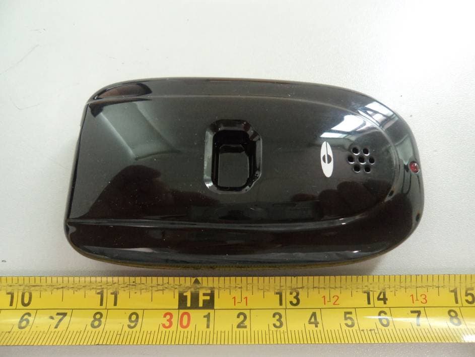
QQ715920
Mar 16, 2012ITAG
Equipment Class
DSR - Part 15 Remote Control/Security Device Transceiver
QQ7EGUARDRC900N
Mar 15, 2011Remote controller
Equipment Class
DXX - Part 15 Low Power Communication Device Transmitter
QQ7EGUARD15921N
Nov 29, 2010Removal Alert Tag
Equipment Class
DSR - Part 15 Remote Control/Security Device Transceiver
QQ7EGUARDEAS02
May 19, 2003Swept Frequency Anti-pilferage Device
Equipment Class
FAP - Part 15 Anti-Pilferage Device