QQ7EGUARD7600Commodity Protector
Shenzhen Ronghua Electronic Co. Ltd.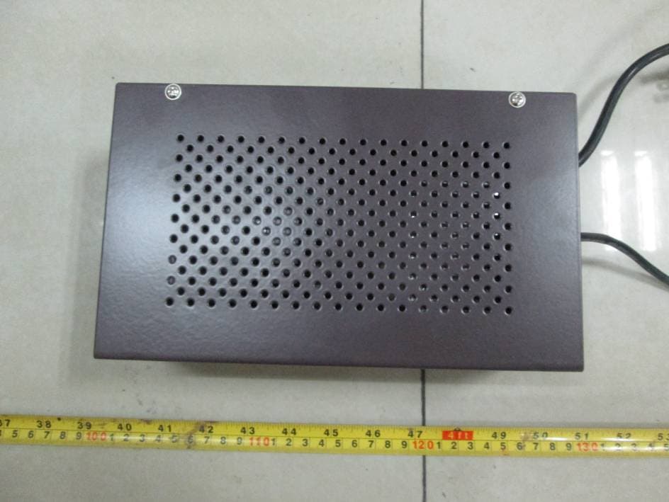
Click to zoom
Application Details
- Equipment Class
- DXX - Part 15 Low Power Communication Device Transmitter
- Date of Grant
- Mar 13, 2015
- Application Purpose
- Original Equipment
- Date of Application
- Mar 13, 2015
- Equipment Note
- Commodity Protector
- Frequency Range
- 8.20000000 - 8.20000000
- Country
- China
Documents & Files
Document Text
Text extracted from the exhibit documents filed with the FCC. Open a document above to read the original.
Users Manual
TR7600 RF Transceiver Summary Normal conditions Operating temperature : 0°C ~ 40°C Storage temperature : - 40°C ~ 60°C Humidity : 5% ~ 95% Technical Specifications Operating voltage : 24VDC Operating current : 400+/‐30Ma (max) Safety fuse : 250V, 1A (delay) Operating frequency : center frequency 8.2MHz (adjustable 7.6~8.9MHz) Detection speed : ≥2m/s Power Supply EG107 : built‐in power supply PCB, one power supply per antenna Input voltage : 120VAC 50/60Hz (voltage range 187 ~ 242 VAC) Output voltage : 24VAC 1400mA Wire connection : 30m (max, Ø0.3mm) Detection TR7600 PCB can be used in EG2266, EG2268, EG2280 and EG2288 antenna frames. For multiple antennae installation, synchronization is necessary. Table 1 shows the detection in thegeneralenvironment: Table 1 Model Tag/Label Detection EG2266/EG2288/EG2268 4x4cm label Average 0.75m, Max 1m(per side) UFO tag(Q≥220) (15767,Ø0.55mm) Average 1m, Max 1.3m(per side) When positioning antennae, take note of high power equipment such as air‐conditioning, freezer, soldering machine, etc. and data line such as power line, communication cable, CCTV cable, etc. as this would cause interference to systems. It is best to keep a distance of 0.6m apart. We strongly suggest testing the system at the desired site without securing the nuts and bolts before permanently fixing into position. Often repositioning the system by a few cm may resolve interference. RF swept will interfere RF transceiver systems if placed within 10m from RF transceiver. If there is interference, the detection of RF transceiver will reduce by 20~30%. Installation Multiple antennae To maximize detection distance and minimize interference between systems, we recommend synchronizing each antenna by interconnecting them. Here belowis a diagram explaining the interconnecting of systems at multiple installations: Note: NOTES: 1. Shielded twisted pair cable should be used for connection. 2. The maximum distance of the whole interconnection is 50m, i.e. the connection distance count from the first antenna to the last antenna should be less than 50m. 3. Each set of antennae can have only one Master and the other Slaves. One Master antenna can link with a maximum of 30 Slave antennae. 4. Distance of each synchronization cable should not be more than 30cm from main cable. Master Antennae Set‐up Select any one of the antennae as Master and in that PCB, J203, short‐circuit 7&8 by placing plastic cap as shown below. In the Red selector next to J203, choose one number out of 1 to 6 and turn to ON. In the diagram below, 1 is selected. If there is another set of antennae with another Master, a different number should be used. Slave Antenna Set‐up For the Slaves, do not short circuit any one of the connectors at J203 above. In the Red selector next to J203, select the same number to ON position as per Master. In the diagram above, 1 is selected. For another set with different Master, use the number as indicated in that particular Master. Synchronization J104 is the connector for synchronization. There are threecolors on it:‐ Black : GND (connect to shielded layer of the twisted pair cable) Red : SH (connect tohigh signal cable) White : SL (connect tolow signal cable) At either end of the multiple connections (namely, the first and the last antenna), J101 needs to be short circulated i.e. closing with a plastic cap. J203 Software Tuning In normal circumstances, there is no need for software adjustments as at factory setting, the electronics are set to the optimal level. However, should the environmental condition differ significantly or there are strong interference, changing the system settings via software may enhance system operation. a, Prior to using the software: J102 in PCB should be short circulated by placing plastic cap. Once adjustment is made, the plastic cap in J102 should be disconnected. b, Reset to Factory Setting: 1. short circuit J102 by placing plastic cap 2. short circuit 5& 6 at J203 by placing plastic cap 3. press RESET and allow PCB to restart 4. when self-testing completes, disconnect the plastic cap in 5&6 at J203. 5. disconnect the plastic cap in J102 6. press RESET again c, USB Connection: Connect one end of the USB to the computer and the other end to the PCB. Open the software program and the software will indicate available COMM drive. Select desired COMM drive and when all connected properly, Successful Connection will show. d, Menu: There are five headings: [Parameter setting], [Parameter query], [Data display], [Record data] and [Setting]: J104 J101 J102 Reset J300 SAVE and LOAD LOAD: will transmit the latest setting to the PCB but it will not SAVE. It is used to check performance based on changes but when machine is turned off, the latest setting will not be saved. SAVE: after LOAD then press SAVE and the latest setting will be saved and operate when machine restarts. Under [Set‐up], there are seven settings:‐ 1, Transmission Setting Center frequency: 8.2 factory setting, others 8.6, 9.0, 9.5 Frequency range: 7.6~8.7 factory setting, range from 7.4~10 Mode: n.a. On/Off: ON, when label is detected, transmission power will reduce OFF, no change to transmission power (factory setting) 2, Receiver Setting [coding]: to shield interference signal. Refer to [Data]. Factory setting FFFF. [filter]: four types of filter to counter noise A, B C and D. D strongest but detection time slowest. Factory setting A. [Hard tags]: n.a. [ ]: n.a. 3, Date and Time Synchronize time and date to PCB 4 , Antenna configuration 1 Transmission power: 0 ~ 31 (31 being highest). Factory setting, 28 Receiver gain: 0 ~ 31 (31 being highest). Factory setting, 28 5, Antenna configuration 2, as per above 6, [Gate adjustment], refer to [Data] [Gate A]: factory setting 0, range from 0 ~ 200 [Gate B]: factory setting 0, range from 0 ~ 200 7, Alarm volume Adjustment level: 0 ~ 31 For PCB with R258 adjustment, volume adjust manually. Under [Set‐upConfig], there are three keys”:‐ 1, [Clear]: clear all entries 2…
Text truncated - open the document above for the full version.
External Photos
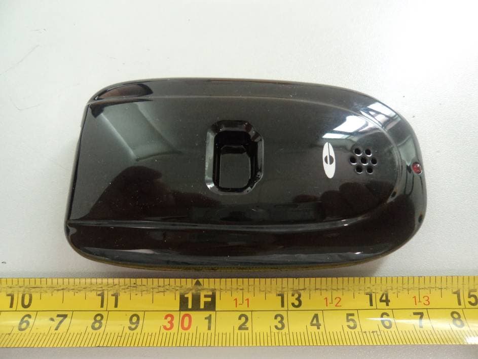
EXHIBIT B - EUT EXTERNAL PHOTOGRAPHS EUT – Front View EUT – Rear View EUT – Top View EUT – Bottom View EUT – Left Side View EUT – Right Side View EUT – Front View (DC Power) EUT – Rear View (DC Power) EUT – Top View (DC Power) EUT – Bottom View (DC Power) EUT – Left Side View (DC Power) EUT – Right Side View (DC Power)
ID Label/Location Info
EXHIBIT A - FCC ID LABELING AND LOCATION FCC ID Label FCC ID Label Location The label shown shall be permanently affixed at a conspicuous location on the device and be readily visible to the user at the time purchase (Labeling requirements per 2.925) Label here
Internal Photos
EXHIBIT C - EUT INTERNAL PHOTOGRAPHS EUT –Cover off View EUT – Main Board Top View Antenna EUT – Main Board Bottom View EUT –Buzzer Top View EUT –Buzzer Bottom View EUT –Cover off View (DC Power) EUT – Main Board Top View (DC Power) EUT – Main Board Bottom View (DC Power) EUT – Main Board Bottom View Shielding off(DC Power) EUT –Transformer View (DC Power) EUT –Transformer Label View (DC Power)
Test Report
Note: This test report is prepared for the customer shown above and for the equipment described herein. It may not be duplicated or used in part without prior written consent from Bay Area Compliance Laboratories Corp. FCC PART 15.223 TEST REPORT For Shenzhen Ronghua Electronic Co., Ltd. Building 1, Quanxinyuan Industrial Park, Huafan Road, Dalang Sub-district, Longhua, Bao'an District, Shenzhen FCC ID: QQ7EGUARD7600 Report Type: Original Report Product Type: Commodity protector Test Engineer: Simon Wang Report Number: RSZ141023003-00 Report Date: 2014-12-29 Reviewed By: Jimmy Xiao RF Engineer Prepared By: Bay Area Compliance Laboratories Corp. (Shenzhen) 6/F, the 3rd Phase of WanLi Industrial Building, ShiHua Road, FuTian Free Trade Zone Shenzhen, Guangdong, China Tel: +86-755-33320018 Fax: +86-755-33320008 www.baclcorp.com.cn Bay Area Compliance Laboratories Corp. (Shenzhen) Report No.: RSZ141023003-00 FCC Part 15.223 Page 2 of 23 TABLE OF CONTENTS GENERAL INFORMATION ....................................................................................................................................... 4 PRODUCT DESCRIPTION FOR EQUIPMENT UNDER TEST (EUT) ..................................................................................... 4 OBJECTIVE ................................................................................................................................................................... 4 RELATED SUBMITTAL(S)/GRANT(S) ............................................................................................................................. 4 TEST METHODOLOGY .................................................................................................................................................. 4 TEST FACILITY ............................................................................................................................................................. 4 SYSTEM TEST CONFIGURATION .......................................................................................................................... 5 JUSTIFICATION ............................................................................................................................................................. 5 EUT EXERCISE SOFTWARE .......................................................................................................................................... 5 EQUIPMENT MODIFICATIONS ....................................................................................................................................... 5 EXTERNAL I/O CABLE .................................................................................................................................................. 5 BLOCK DIAGRAM OF TEST SETUP ................................................................................................................................ 5 SUMMARY OF TEST RESULTS ............................................................................................................................... 6 FCC§15.203 - ANTENNA REQUIREMENT .............................................................................................................. 7 APPLICABLE STANDARD .............................................................................................................................................. 7 ANTENNA CONNECTED CONSTRUCTION ...................................................................................................................... 7 FCC §15.207 – AC LINE CONDUCTED EMISSION ............................................................................................... 8 APPLICABLE STANDARD .............................................................................................................................................. 8 MEASUREMENT UNCERTAINTY .................................................................................................................................... 8 EUT SETUP .................................................................................................................................................................. 8 EMI TEST RECEIVER SETUP ......................................................................................................................................... 9 TEST EQUIPMENT LIST AND DETAILS ........................................................................................................................... 9 TEST PROCEDURE ........................................................................................................................................................ 9 CORRECTED FACTOR & MARGIN CALCULATION ....................................................................................................... 10 TEST RESULTS SUMMARY .......................................................................................................................................... 10 TEST DATA ................................................................................................................................................................ 10 FCC§15.223, §15.205 & §15.209 - RADIATED EMISSIONS TEST ...................................................................... 13 APPLICABLE STANDARD ............................................................................................................................................ 13 MEASUREMENT UNCERTAINTY .................................................................................................................................. 13 EUT SETUP ................................................................................................................................................................ 13 EMI TEST RECEIVER SETUP ....................................................................................................................................... 14 CORRECTED AMPLITUDE & MARGIN CALCULATION ............................…
Text truncated - open the document above for the full version.
Contact Information
Applicant
Guixing Chang(Engineer)
Test Firm
Bay Area Compliance Laboratory Corp. (Shenzhen)John Chan
Technical Specifications
| # | Rule Parts | Frequency Range | Power Output |
|---|---|---|---|
| 1 | 15C | 8.2 MHz - 8.2 MHz | - |
Other Applications from Shenzhen Ronghua Electronic Co. Ltd.
QQ715920
Mar 16, 2012ITAG
Equipment Class
DSR - Part 15 Remote Control/Security Device Transceiver
QQ7EGUARDRC900N
Mar 15, 2011Remote controller
Equipment Class
DXX - Part 15 Low Power Communication Device Transmitter
QQ7EGUARD15921N
Nov 29, 2010Removal Alert Tag
Equipment Class
DSR - Part 15 Remote Control/Security Device Transceiver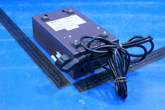
QQ7EGUARDEG3388
Jun 21, 2010Electronic Article Surveillance
Equipment Class
FAP - Part 15 Anti-Pilferage Device
QQ7EGUARDEAS02
May 19, 2003Swept Frequency Anti-pilferage Device
Equipment Class
FAP - Part 15 Anti-Pilferage Device