QTZ1200DIEEE 802.11 a/g Wireless LAN Access Point
Airespace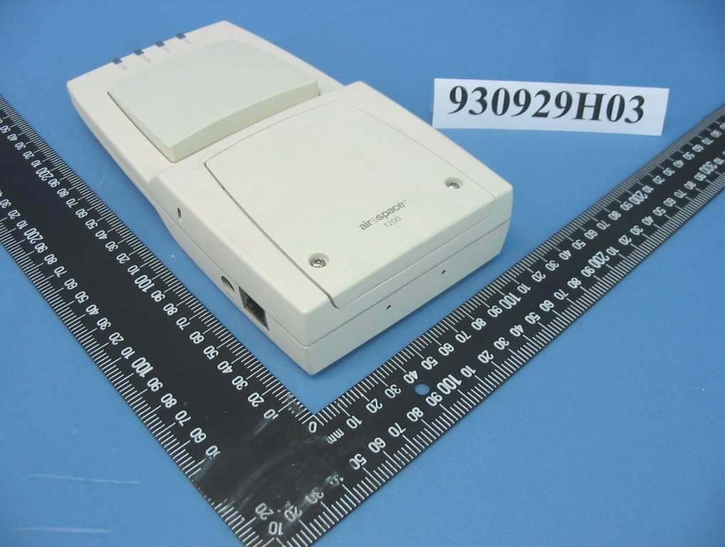
Click to zoom
Application Details
- Equipment Class
- NII - Unlicensed National Information Infrastructure TX
- Date of Grant
- Dec 16, 2004
- Application Purpose
- Original Equipment
- Date of Application
- Dec 16, 2004
- Equipment Note
- IEEE 802.11 a/g Wireless LAN Access Point
- Frequency Range
- 5260.00000000 - 5320.00000000
- Company
- Airespace
- Country
- United States
Documents & Files
Document Text
Text extracted from the exhibit documents filed with the FCC. Open a document above to read the original.
Users Manual
11/16/04© 2004 All Rights Reserved. 90-100905-000 Rev 1 Internal-Antenna 1200 and 1250 Airespace AP Quick Installation GuideInternal-Antenna Airespace Access Point Quick Installation Guide System Release 2.1 This Guide contains several sections allowing you to install an AS-1200-BG-INT, OAW-1250BG, AS-1200-ABG-INT, or OAW-1250ABG Airespace Access Point. These models contain internal 802.11a and 802.11b/g antennas and no connectors for optional external antennas. When you are installing an AS-1200-BG-EXT, OAW-1250BGE, AS-1200-ABG-EXT, OAW-1250ABGE Airespace Access Point, an AS-1200-ABG-EXT-RE or OAW-1250ABGR Remote Edge Access Point (REAP) with internal 802.11a and 802.11b/g antennas and connectors for optional external 802.11a and 802.11b/g antennas, please refer to the External-Antenna Airespace Access Point Quick Installation Guide. •Overview •Step 1: Collecting Required Tools and Supplies •Step 2: Configuring the Airespace AP Before Installation •Step 3: Preparing Mounting Locations •Step 4: Mounting the Airespace APs •Step 5: Returning MAC Information •Planning Notes •FCC Statements for Airespace APs •Industry Canada Required User Information for Airespace APs ATTENTION!Special Considerations While Airespace Access Points have been engineered for easy installation, there are some guidelines that are very important to the end users: •PLACE Airespace APs NO MORE THAN 140 FEET APART FROM EACH OTHER. Placing Airespace APs further apart almost always results in poor coverage. •DO NOT MOUNT Airespace APs OUTSIDE BUILDINGS. •DO NOT MOUNT Airespace APs ON BUILDING PERIMETER WALLS UNLESS THE OPERATOR WANTS TO PROVIDE COVERAGE OUTSIDE THE BUILDING. •MAKE SURE that plenum-mounted Airespace APs are powered using Power Over Ethernet (POE) and use only the metal brackets (not the Ceiling-Mount Base or the Hanging-Ceiling Clips) to comply with safety regulations. 11/16/04Internal-Antenna Airespace Access Point Quick Installation Guide 90-100905-000 Rev 12 •MAKE SURE THAT Airespace APs ARE INSTALLED VERTICALLY. When Airespace APs are installed vertically, either standing up in a plenum or hanging from a ceiling, this creates the largest coverage area per Airespace AP. Hanging Airespace APs from the ceiling provides the best RF coverage. •DO NOT MOUNT Airespace AP ANTENNAS WITHIN ONE METER (3 FT.) OF ANY METAL OBSTRUCTIONS. THE RF WAVES FROM Airespace APs ARE BLOCKED AND/OR REFLECTED BY METAL OBJECTS, such as metal HVAC ducts, conduit, pipes, bookcases, elevator shafts, stairwells, and metal walls. REFER TO THE Airespace Access Point Deployment Guide BEFORE MOUNTING Airespace APs NEAR METAL OBSTRUCTIONS. •WHEN MOUNTING AN Airespace AP IN THE CORNER OF A RIGHT-ANGLE HALLWAY INTERSECTION, MOUNT THE Airespace AP AT A 45-DEGREE ANGLE TO THE TWO HALLWAYS. The Airespace AP internal antennas are not omnidirectional, and cover a larger area when mounted this way. 11/16/04Overview 90-100905-000 Rev 13 OverviewOverview This guide is designed to provide you with the information needed to mount AS-1200-BG-INT, OAW-1250BG, AS-1200-ABG-INT, and OAW-1250ABG Airespace Access Points (Airespace APs). Airespace APs are part of the innovative Airespace Wireless Enterprise Platform (Airespace System), and require no manual configuration after they are mounted. This document assumes that a site survey has been performed as described in the Airespace Access Point Deployment Guide document, that Airespace AP locations and mounting options have been selected, and that you have one Airespace AP per indicated location. After the site survey is done, you should have a map indicating the following: •Airespace AP locations. •Airespace AP mounting options: hanging from a ceiling, in the ceiling plenum, projecting away from the wall, flat against the wall, or using the Ceiling-Mount Bezel Kit. •Airespace AP power options: power supplied by the AC-to-DC power supply orderable from the factory, or Power over Ethernet (PoE) from the Airespace WLAN Switch, another network device, or a PoE injector/hub (usually located in a wiring closet). If you do not have a map, make one so you can record the MAC addresses from each location and return them to the to the person who is planning or managing this wireless network. Refer to the following sections to install the Airespace APs. For more details about Airespace AP installations, refer to the Planning Notes section at the end of this document. Note: Plenum-mounted Airespace APs and REAPs MUST BE powered using Power Over Ethernet (POE) to comply with safety regulations. Note: When mounting Airespace APs, make sure to maintain a 20 cm (8 in.) separa- tion between the Airespace APs and bystanders to comply with FCC RF exposure regulations. Refer to the FCC Statements for Airespace APs section for more information. 11/16/04Step 1: Collecting Required Tools and Supplies 90-100905-000 Rev 14 Step 1: Collecting Required Tools and SuppliesStep 1: Collecting Required Tools and Supplies •One Airespace AP or REAP per location. •Airespace AP and REAP Mounting Kits, factory-supplied with each Airespace AP. •Optional Airespace AP Mounting Kits, factory-orderable. •Optional AC-to-DC external power supplies, factory-orderable. Note that this option requires the power cable to be run through the plenum in a metal conduit to meet safety requirements. •Map showing Airespace AP locations, and mounting and power options. •Screwdrivers, drills, and ladder. •An assortment of sheet metal and drywall screws and toggle bolts. •CAT-5 (or higher) cables to connect the Airespace AP and REAP locations and the Airespace WLAN Switch or other network device. •Optional Kensington MicroSaver Security Cable to secure each Airespace AP. Continue with Step 2: Configuring the Airespace AP Before Installation . 11/16/04Step 2: Configuring the Airespace AP Before Installation 90-100905-000 Rev 15 Step 2: Configuring the Airespace AP Before InstallationStep 2: Configuring the Airespace AP Before Installation The following procedures…
Text truncated - open the document above for the full version.
Cover Letter(s)
American Telecommunications Certification Body Inc. 6731 Whittier Ave, McLean, VA 22101 December 1, 2004 RE: Airespace, Inc. FCC ID: QTZ1200D After a review of the submitted information, I have a few comments on the above referenced Application. 1) The POA is not dated. Please revise. 2) Please provide information regarding the external antenna for use with this device. Additionally, please provide the Airespace Product Guide referenced in the users manual that discusses these antennas. 3) Please explain why external antennas do not appear to have been tested. 4) Page 11 of the test report discusses external antennas that may be used but only mentions gain. Note that not any antenna of lesser gain can be used. Only antenna of the same type (defined as antennas of similar in-band and out of band emissions patterns) can be used. 5) For conducted emissions, it appears that POE and AC adapter were used. However the block diagrams in the report does not appear to show this. Please review/correct as necessary. 6) How was the device powered in the first configuration shown in the block diagrams in the report. 7) If the device can TX simultaneously (previous version of this device did), then simultaneous EMC emissions must also be performed. Please provide this data. 8) Previous versions of this device required the output power on bandedge channels to be reduced compared to other channels in the band. Please confirm if this was necessary or not. 9) Please explain at what point the power was measured for the 5 GHz. Some previous versions measured the power behind the antenna switch. Because external antennas do not have a switch in place, and the internal antennas do this must be adequately known, otherwise the external antennas will exceed the allowable limits. Please clarify as necessary. 10) Radiated data for a center channel in the 5745 – 5825 MHz band does not appear to have been provided as required by FCC regulations. 11) The test procedure on page 101 does not appear to match the testing. Please explain the settings for both traces. Please correct. 12) MPE calculations must show a composite MPE value. Please update. Timothy R. Johnson Examining Engineer mailto: [email protected] The items indicated above must be submitted before processing can continue on the above referenced application. Failure to provide the requested information may result in application termination. Correspondence should be considered part of the permanent submission and may be viewed from the Internet after a Grant of Equipment Authorization is issued. Please do not respond to this correspondence using the email reply button. In order for your response to be processed expeditiously, you must submit your documents through the AmericanTCB.com website. Also, please note that partial responses increase processing time and should not be submitted. Any questions about the content of this correspondence should be directed to the sender.
Cover Letter(s)
Dear Tim, Today Hank and I went to ATCB Taiwan office to meet Dennis & Major for this complicate project. (many thanks for the details explanation from both of them..) For the comments, (we are processing .. client would like to get the grant .. before next Wed.) Item 1 - Now asking client to provide revised POA 2 - The external antenna is same type as internal antenna (Patch Antenna), we are asking client to add the type of external antenna in user's manual. 3 - Same type of antenna. 4 - Test report will be revised. 5 - Test report will be revised. 6 - Test report will be revised. 7 - We confirmed to our client again, the product can TX simultaneously. The test is done, test report will be revised. 8 - During the test, the bandedge channel power did not be reduced by any bandedge emission issues. 9 - Please check the schematic page 6, we measured the 5 GHz conducted power from connector J502, (J702 is for external antenna). I confirmed with my testing engineer, the both connectors have been checked, the output power is same (The radio output from J502 or J702 can be selected by test program which provided by manufacturer.) 10 - The test is done, test report will be revised. 11 - The test procedure will be revised. 12 - MPE report will be revised to add the TX simultaneous calculation. The electronic files may be upload tomorrow. Any issues for above, please let us know at your earliest convenience. Thanks a lot. Best Regards, æž—æ‡æŒ / Eric Lin
Cover Letter(s)
The following items are our replies for the last remain comments: 1) The POA letter: Done! 2) User's manual: We still wait for our client to provide us the revised file. 4), 5),6),10), 11) Test report: Done! We revised the test report, its file name is "TestRpt-1_QTZ1200D- revised" 7) simultaneous EMC emissions: We add one file and uploaded it to ATCB server, its file name is "TestRpt- 2_QTZ1200D" 12)RF exposure:Done! Besides that, we also revised the 731 form file. The above all files were uploaded to ATCB server today. Please help us check them. If you have any further questions, please contact us ASAP! Thanks! Best Regards, Amanda Chu
External Photos
Page 1 CONSTRUCTION PHOTOS OF EUT For Model: AS-1250-ABG-EXT For Model: AS-1250-ABG-INT Page 2 For Model: AS-1250-ABG-EXT Page 3 For Model: AS-1250-ABG-INT
Internal Photos
Page 1 CONSTRUCTION PHOTOS OF EUT For Model: AS-1250-ABG-EXT Page 2 Page 3 Page 4 Page 5 Page 6 For Model: AS-1250-ABG-INT Page 7 Page 8 Page 9 Page 10 Page 11
Operational Description
FCC ID: QTZ1200D Report No. 930929H03 Technical Description This device is a IEEE 802.11a/g Wireless LAN Access Point operates in both the 5GHz and 2.4GHz bands with DSSS and OFDM technique. The transmitter rate could be 1/2/5.5/6/9/11/12/18/ 24/36/48/54Mbps. The transmitter of the EUT is powered by AC adapter or POE. The antenna is Patch Antenna without connector. Under normal use condition, the user has to keep at least 20 cm separation distance between radiator and the body of the user. For more detailed instruction, please refer to the user’s manual. FCC 15.407(c) states : The device shall automatically discontinue transmission in case of either absence of information to transmit or operational failure. These provisions are not intended to preclude the transmission of control or signaling information or the use of repetitive codes used by certain digital technologies to complete frame or burst intervals. Applicants shall include in their application for equipment authorization a description of hoe this requirement is met. Data transmission is always initiated by software, which is then pass down through the MAC, through the digital and analog baseband, and finally to the RF chip. Several special packets (ACKs, CTS, PSPoll, etc...) are initiated by the MAC. There are the only ways the digital baseband portion will turn on the RF transmitter, which it then turns off at the end of the packet. Therefore, the transmitter will be on only while one of the aforementioned packets are being transmitted.
RF Exposure Info
FCC ID: QTZ1200D ADT No.: 930929H031Issued: Oct. 28, 2004 RF EXPOSURE REPORT REPORT NO.: SA930929H03 MODEL NO.: AS-1250-ABG-INT, AS-1250-ABG-EXT ACCORDING: FCC Guidelines for Human Exposure IEEE C95.1 APPLICANT: Airespace Inc. ADDRESS: 110 Nortech Parkway, San Jose, CA 95134, USA ISSUED BY: Advance Data Technology Corporation LAB LOCATION: No. 81-1, Lu Liao Keng, 9 Ling, Wu Lung Tsuen, Chiung Lin Hsiang, Hsin Chu Hsien, Taiwan, R.O.C. FCC ID: QTZ1200D ADT No.: 930929H032Issued: Oct. 28, 2004 RF Exposure Measurement 1. Introduction In this document, we try to prove the safety of radiation harmfulness to the human body for our product. The limit for Maximum Permissible Exposure (MPE) specified in FCC 1.1310 is followed. The Gain of the antenna used in this product is measured in a Fully Anechoic Chamber (FAC) calibrated for antenna measurement in ADT, and also the maximum total power input to the antenna is measured. Through the Friis transmission formula and the maximum gain of the antenna, we can calculate the distance, away from the product, where the limit of MPE is reached. Although the Friis transmission formula is a far field assumption, the calculated result of that is an over-prediction for near field power density. We will take that as the worst case to specify the safety range. 2. RF Exposure Limit According to FCC 1.1310: The criteria listed in the following table shall be used to evaluate the environmental impact of human exposure to radio-frequency (RF) radiation as specified in 1.1307(b) LIMITS FOR MAXIMUM PERMISSIBLE EXPOSURE (MPE) Frequency Range (MHz) Electric Field Strength (V/m) Magnetic Field Strength (A/m) Power Density (mW/cm 2 ) Average Time (minutes) (A)Limits For Occupational / Control Exposures 300-1500......F/3006 1500-100,000......56 (B)Limits For General Population / Uncontrolled Exposure 300-1500......F/15006 1500-100,000......1.030 F = Frequency in MHz FCC ID: QTZ1200D ADT No.: 930929H033Issued: Oct. 28, 2004 3. Friis Formula Friis transmission formula : Pd = (Pout*G) / (4*pi*r 2 ) where Pd = power density in mW/cm 2 Pout = output power to antenna in mW G = gain of antenna in linear scale Pi = 3.1416 R = distance between observation point and center of the radiator in cm Pd is the limit of MPE, 1 mW/cm 2 . If we know the maximum Gain of the antenna and the total power input to the antenna, through the calculation, we will know the MPE value at distance 20cm. Ref. : David K. Cheng, Field and Wave Electromagnetics, Second Edition, Page 640, Eq. (11-133). 4 EUT Operating condition The software provided by Manufacturer enabled the EUT to transmit and receive data at lowest, middle and highest channel individually. 5. Classification This is a stand alone radio device. So under normal use condition, it is easy to be re- located in the place where at least 20 cm far away from the body of the user. Warning statement to the user for keeping at least 20cm or more separation distance with the antenna should be included in users manual. So, this device is classified as Mobile Device. FCC ID: QTZ1200D ADT No.: 930929H034Issued: Oct. 28, 2004 6 Test Results 6.1 Antenna Gain For 2.4GHz The maximum Gain measured in Fully Anechoic Chamber is 7.8dBi or 6.0256 (numeric). For 5GHz The maximum Gain measured in Fully Anechoic Chamber is 7.4dBi or 5.49541 (numeric). 6.2 Output Power Into Antenna & RF Exposure value at distance 20cm: For 2.4GHz 802.11b: Channel Channel Frequency (MHz) Output Power to Antenna (mW) Power Density (mW/cm 2 ) Limit of Power Density (mW/cm 2 ) 12412130.91819230.1569383671.0 62437116.41260290.1395497711.0 112462109.90058390.1317434791.0 802.11g: Channel Channel Frequency (MHz) Output Power to Antenna (mW) Power Density (mW/cm 2 ) Limit of Power Density (mW/cm 2 ) 12412125.0259030.1498749771.0 62437113.50108160.1360595811.0 112462111.42945340.1335762141.0 For 5GHz Normal Mode : Channel Channel Frequency (MHz) Output Power to Antenna (mW) Power Density (mW/cm 2 ) Limit of Power Density (mW/cm 2 ) 1518031.98895110.0349726971.0 4524034.040818970.0372159521.0 55260125.89254120.1376350771.0 85320111.68632480.1221037861.0 95745134.89628830.1474786421.0 135825127.64388090.1395497711.0 FCC ID: QTZ1200D ADT No.: 930929H035Issued: Oct. 28, 2004 For 2.4GHz Using the highest power measured on the 2.4GHz ISM Band. MAX Pout: (mW) =130.9181923 EIRP(mW)=770.9 For 5GHz Normal Mode : Using the highest power measured on the 5GHz Band. MAX Pout:(mW)=134.896 EIRP(mW):=741.3 For transmit simultaneously Total EIRP(mw): 770.9+741.3=1512.2 Calculating power density at a distance of 20 cm yields: Power Density=0.30084 mw/cm 2 below limit
Test Report
FCC ID: QTZ1200D Report No.: RF930929H031Report Format Version 2.0.0 FCC TEST REPORT REPORT NO.: RF930929H03 MODEL NO.: AS-1250-ABG-INT, AS-1250-ABG-EXT RECEIVED: Sep. 29, 2004 TESTED: Oct. 08 to Nov. 01, 2004 ISSUED: Nov. 05, 2004 APPLICANT: Airespace Inc. ADDRESS: 110 Nortech Parkway, San Jose, CA 95134, USA ISSUED BY: Advance Data Technology Corporation LAB LOCATION: No. 81-1, Lu Liao Keng, 9 Ling, Wu Lung Tsuen, Chiung Lin Hsiang, Hsin Chu Hsien, Taiwan, R.O.C. This test report consists of 146 pages in total. It may be duplicated completely for legal use with the approval of the applicant. It should not be reproduced except in full, without the written approval of our laboratory. The client should not use it to claim product endorsement by CNLA, A2LA or any government agencies. The test results in the report only apply to the tested sample. The test results in this report are traceable to the national or international standards. 0536No. 2177-01 ILAC MRA FCC ID: QTZ1200D Report No.: RF930929H032Report Format Version 2.0.0 Table of Contents 1.CERTIFICATION .................................................................................................................... 6 2.SUMMARY OF TEST RESULTS............................................................................................ 7 3.GENERAL INFORMATION .................................................................................................. 10 3.1GENERAL DESCRIPTION OF EUT..................................................................................... 10 3.2GENERAL DESCRIPTION OF APPLIED STANDARDS...................................................... 13 3.3DESCRIPTION OF SUPPORT UNITS................................................................................. 14 3.4CONFIGURATION OF SYSTEM UNDER TEST.................................................................. 15 4.TEST TYPES AND RESULTS (FOR PART 802.11G) .......................................................... 18 4.1CONDUCTED EMISSION MEASUREMENT....................................................................... 18 4.1.1LIMITS OF CONDUCTED EMISSION MEASUREMENT .................................................... 18 4.1.2TEST INSTRUMENTS ......................................................................................................... 18 4.1.3TEST PROCEDURES .......................................................................................................... 19 4.1.4DEVIATION FROM TEST STANDARD ................................................................................ 19 4.1.5TEST SETUP ....................................................................................................................... 20 4.1.6EUT OPERATING CONDITIONS......................................................................................... 20 4.1.7TEST RESULTS ................................................................................................................... 21 4.2RADIATED EMISSION MEASUREMENT............................................................................ 25 4.2.1LIMITS OF RADIATED EMISSION MEASUREMENT ......................................................... 25 4.2.2TEST INSTRUMENTS ......................................................................................................... 26 4.2.3TEST PROCEDURES .......................................................................................................... 27 4.2.4DEVIATION FROM TEST STANDARD ................................................................................ 27 4.2.5TEST SETUP ....................................................................................................................... 28 4.2.6EUT OPERATING CONDITIONS......................................................................................... 28 4.2.7TEST RESULTS ................................................................................................................... 29 4.2.8TEST RESULTS - DSSS ...................................................................................................... 31 4.2.9TEST RESULTS - OFDM ..................................................................................................... 34 4.36DB BANDWIDTH MEASUREMENT................................................................................... 37 4.3.1LIMITS OF 6DB BANDWIDTH MEASUREMENT ................................................................ 37 4.3.2TEST INSTRUMENTS ......................................................................................................... 37 4.3.3TEST PROCEDURE ............................................................................................................38 4.3.4DEVIATION FROM TEST STANDARD ................................................................................ 38 4.3.5TEST SETUP ....................................................................................................................... 38 4.3.6EUT OPERATING CONDITIONS......................................................................................... 38 4.3.7TEST RESULTS -DSSS ....................................................................................................... 39 4.3.8TEST RESULTS -OFDM ...................................................................................................... 43 4.4MAXIMUM PEAK OUTPUT POWER ................................................................................... 47 4.4.1LIMITS OF MAXIMUM PEAK OUTPUT POWER MEASUREMENT ................................... 47 4.4.2INSTRUMENTS.................................................................................................................... 47 4.4.3TEST PROCEDURES .......................................................................................................... 48 4.4.4TEST SETUP ....................................................................................................................... 48 4.4.5EUT OPERATING CONDITIONS…
Text truncated - open the document above for the full version.
Test Report
FCC ID: QTZ1200D Report No.: RF930929H03-011Report Format Version 2.0.0 Supplemental “Dual Xmit” Test Report REPORT NO.: RF930929H03-01 MODEL NO.: AS-1250-ABG-INT, AS-1250-ABG-EXT RECEIVED: Sep. 29, 2004 TESTED: Dec. 09, 2004 ISSUED: Dec. 10, 2004 APPLICANT: Airespace Inc. ADDRESS: 110 Nortech Parkway, San Jose, CA 95134, USA ISSUED BY: Advance Data Technology Corporation LAB LOCATION: No. 81-1, Lu Liao Keng, 9 Ling, Wu Lung Tsuen, Chiung Lin Hsiang, Hsin Chu Hsien, Taiwan, R.O.C. This test report consists of 10 pages in total. It may be duplicated completely for legal use with the approval of the applicant. It should not be reproduced except in full, without the written approval of our laboratory. The client should not use it to claim product endorsement by CNLA, A2LA or any government agencies. The test results in the report only apply to the tested sample. The test results in this report are traceable to the national or international standards. 0536No. 2177-01 ILAC MRA FCC ID: QTZ1200D Report No.: RF930929H03-012Report Format Version 2.0.0 Table of Contents 1.CERTIFICATION .................................................................................................................... 3 2.DUAL XMIT, RADIATED EMISSION MEASUREMENT......................................................... 4 2.1LIMITS OF RADIATED EMISSION MEASUREMENT ........................................................... 4 2.2TEST INSTRUMENTS ........................................................................................................... 5 2.3TEST PROCEDURES ............................................................................................................ 6 2.4DEVIATION FROM TEST STANDARD .................................................................................. 6 2.5TEST SETUP ......................................................................................................................... 7 2.6EUT OPERATING CONDITIONS........................................................................................... 8 2.7TEST RESULTS ..................................................................................................................... 9 3.INFORMATION ON THE TESTING LABORATORIES......................................................... 10 FCC ID: QTZ1200D Report No.: RF930929H03-013Report Format Version 2.0.0 1. CERTIFICATION PRODUCT : IEEE 802.11a/g Wireless LAN Access Point BRAND NAME : Airespace MODEL NO. : AS-1250-ABG-INT, AS-1250-ABG-EXT TESTED: Dec. 09, 2004 APPLICANT : Airespace Inc. TEST ITEM: ENGINEERING SAMPLE STANDARDS : 47 CFR FCC Part 15, Subpart C ANSI C63.4-2003 PREPARED BY : , DATE:Dec. 10, 2004 ( Amanda Chu ) TECHNICAL ACCEPTANCE :, DATE:Dec. 10, 2004 Responsible for RF ( Hank Chung ) APPROVED BY : , DATE: Dec. 10, 2004 ( Eric Lin, Manager ) Note: Per a request of the FCC, the access point radio was tested for radiated emissions in restricted bands while transmitting on both 2.4 GHz and 5 GHz at simultaneously. FCC ID: QTZ1200D Report No.: RF930929H03-014Report Format Version 2.0.0 2. DUAL XMIT, RADIATED EMISSION MEASUREMENT 2.1 LIMITS OF RADIATED EMISSION MEASUREMENT Field strength limits are at the distance of 3 meters, emissions radiated outside of the specified bands, shall be according to the general radiated limits in 15.209 as following: Frequencies (MHz) Field strength (microvolts/meter) Measurement distance (meters) 0.009-0.4902400/F(kHz)300 0.490-1.70524000/F(kHz)30 1.705-30.03030 30-881003 88-2161503 216-9602003 Above 9605003 NOTE: 1. The lower limit shall apply at the transition frequencies. 2. Emission level (dBuV/m) = 20 log Emission level (uV/m). 3. As shown in 15.35(b), for frequencies above 1000MHz, the field strength limits are based on average detector, however, the peak field strength of any emission shall not exceed the maximum permitted average limits, specified above by more than 20dB under any condition of modulation. FCC ID: QTZ1200D Report No.: RF930929H03-015Report Format Version 2.0.0 2.2 TEST INSTRUMENTS DESCRIPTION & MANUFACTURER MODEL NO.SERIAL NO. CALIBRATED UNTIL HP Spectrum Analyzer8594E3710A04861Sep. 23, 2005 ADVANTEST Spectrum AnalyzerR3271A85060311Jun. 29, 2005 CHASE RF Pre_AmplifierCPA92321057Aug. 06, 2005 HP Pre_Amplifier8449B3008A01922Oct. 13, 2005 ROHDE & SCHWARZ Test Receiver ESCS30100287Dec. 11, 2004 CHASE Broadband AntennaVULB9168138May 22, 2005 Schwarzbeck Horn_AntennaBBHA9120D124Jun. 16, 2005 Schwarzbeck Horn_AntennaBBHA 9170BBHA9170192Feb. 16, 2005 SCHWARZBECK Tunable Dipole Antenna UHAP897Mar. 07, 2005 SCHWARZBECK Tunable Dipole Antenna VHAP880Mar. 07, 2005 RF Switches (ARNITSU)CS-2011565157Jul. 16, 2005 RF CABLE (Chaintek) 1GHz-20GHz SF10222054-2Feb. 10. 2005 RF Cable(RICHTEC)9913-30M STCCAB-30M- 1GHz-021 Jul. 16, 2005 SoftwareAS60P8NANA CHANCE MOST Antenna Tower AT-1000203NA CHANCE MOST Turn TableTT-1000203NA Note: 1. The calibration interval of the above test instruments is 12 months (36 months for Tunable Dipole Antenna)and the calibrations are traceable to NML/ROC and NIST/USA. 2. The horn antenna and HP preamplifier (model: 8449B) are used only for the measurement of emission frequency above 1GHz if tested. 3. The test was performed in ADT Open Site No. C. 4. The FCC Site Registration No. is 656396. 5. The VCCI Site Registration No. is R-1626. 6. The CANADA Site Registration No. is IC 4824-3. 7. The measurement uncertainty is 3.56 dB, which is calculated as per the document CISPR 16-4 FCC ID: QTZ1200D Report No.: RF930929H03-016Report Format Version 2.0.0 2.3 TEST PROCEDURES a. The EUT was placed on the top of a rotating table 0.8 meters above the ground at a 10 meter open area test site. The table was rotated 360 degrees to determine the position of the highest radiation. b. The EUT was set 3 meters away from the interference-receiving antenna, which was mounted on the top of a variable-height antenna tower. c. The antenna is a broadband antenna, and its height is varied from one meter to four meters ab…
Text truncated - open the document above for the full version.
Test Setup Photos
FCC ID: QTZ1200D Report No.: RF930929H03139Report Format Version 2.0.0 6. PHOTOGRAPHS OF THE TEST CONFIGURATION CONDUCTED EMISSION TEST (With Adapter) FCC ID: QTZ1200D Report No.: RF930929H03140Report Format Version 2.0.0 CONDUCTED EMISSION TEST (With POE) FCC ID: QTZ1200D Report No.: RF930929H03141Report Format Version 2.0.0 RADIATED EMISSION TEST (With Adapter) FCC ID: QTZ1200D Report No.: RF930929H03142Report Format Version 2.0.0 RADIATED EMISSION TEST …
Text truncated - open the document above for the full version.
Contact Information
Applicant
Bob Friday(Sr. Scientist)
Technical Contact
Advance Data Technology CorporationEric Lin
[email protected]+886-3-593-5343
81-1 Luliaoken, 9th Lin, Wulung Tsuen · Hsinchu · Taiwan
Non-Technical Contact
Advance Data Technology CorporationEric Lin
[email protected]+886-3-593-5343
Test Firm
Bureau Veritas CPS (H.K.) Ltd. Taoyuan BranchRichard Chen
Technical Specifications
| # | Rule Parts | Frequency Range | Power Output |
|---|---|---|---|
| 2 | 15E | 5.26 GHz - 5.32 GHz | 126.00 mW |
Other Applications from Airespace
QTZ1300
Mar 30, 2005Outdoor Access Point
Equipment Class
DTS - Digital Transmission SystemQTZ1200W
Jun 19, 2004802.11 Dual Band Access Point
Equipment Class
DTS - Digital Transmission System
QTZAM1200ABG
Jan 12, 2004802.11 Dual Band Access Point
Equipment Class
DTS - Digital Transmission System
QTZWN1200BG
Dec 17, 20032.4 GHz 802.11 Access Point
Equipment Class
DTS - Digital Transmission System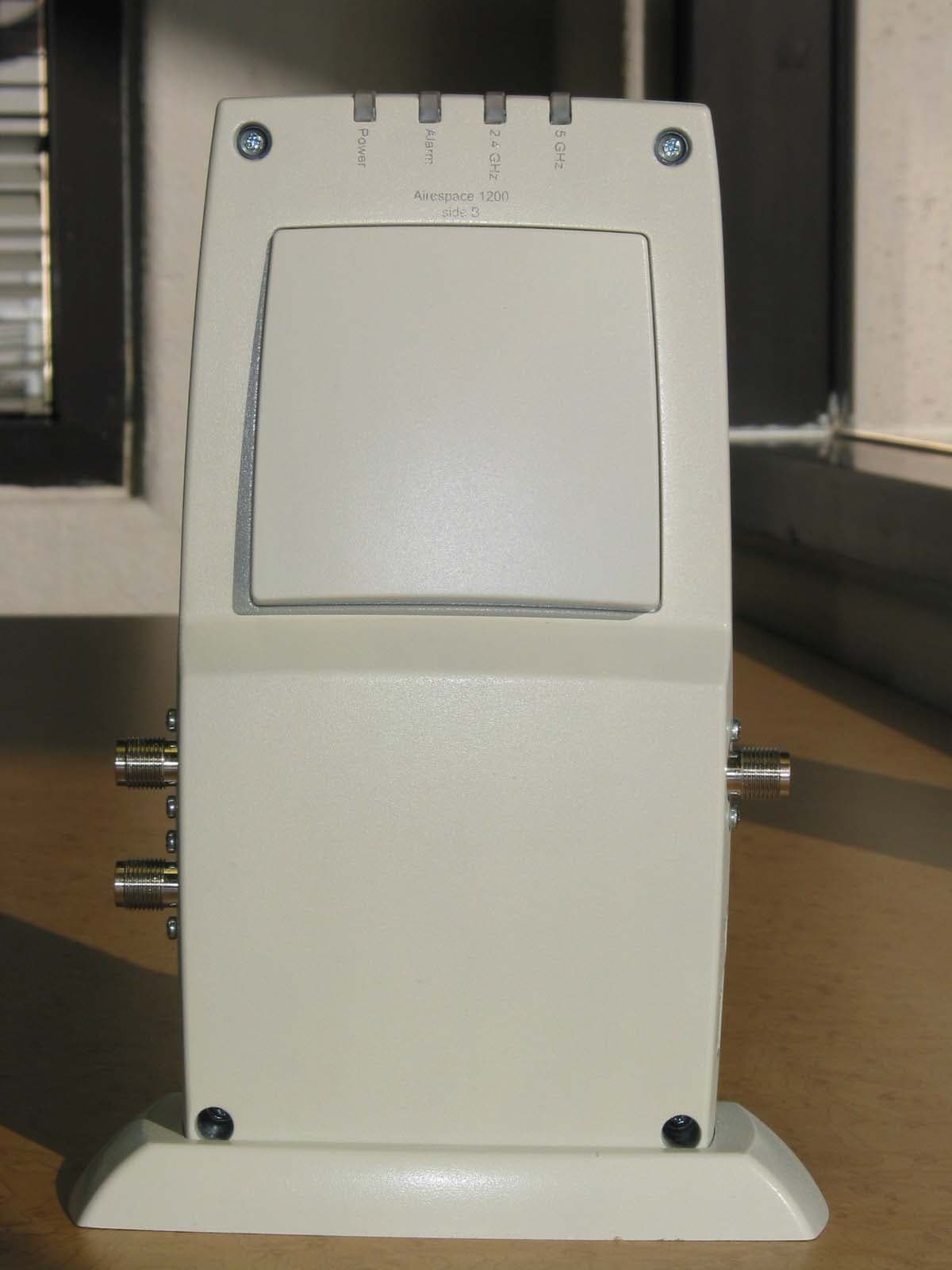
QTZAMAP1200AB
Nov 04, 2003802.11 Dual Band Access Point
Equipment Class
DTS - Digital Transmission System