QTZ1300Outdoor Access Point
Airespace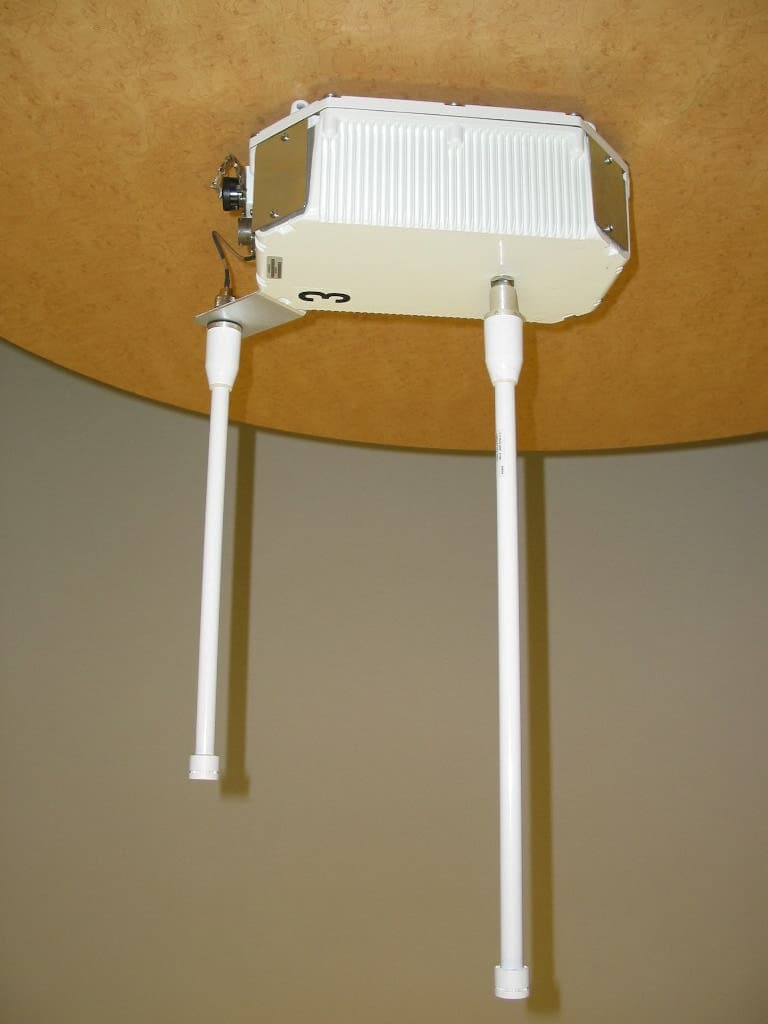
Click to zoom
Application Details
- Equipment Class
- DTS - Digital Transmission System
- Date of Grant
- Mar 30, 2005
- Application Purpose
- Original Equipment
- Date of Application
- Mar 30, 2005
- Equipment Note
- Outdoor Access Point
- Frequency Range
- 5745.00000000 - 5825.00000000
- Company
- Airespace
- Country
- United States
Documents & Files
Document Text
Text extracted from the exhibit documents filed with the FCC. Open a document above to read the original.
Users Manual
3/24/05© 2005 All Rights Reserved. 90-100XXX-001 Airespace 1300 Outdoor Wireless Routing Access Point Quick Installation GuideAirespace 1300 Outdoor Wireless Routing Access Point Quick Installation Guide System Release 3.0 This Guide contains information about installing an Airespace 1300 Outdoor Wireless Routing Access Point (Airespace 1300, or WRAP). This model is designed to be installed outside of a building. It includes connectors for external 802.11a and 802.11b/g antennas. •Overview •Step 1: Collecting Required Tools and Supplies •Step 2: Configuring the Airespace 1300 Before Installation •Step 3: Preparing Mounting Locations •Step 4: Mounting the Airespace 1300s •Step 5: Returning MAC Information •Planning Notes •FCC Statements for Airespace APs •Industry Canada Required User Information for Airespace APs •Safety Considerations •Airespace Global Services & Support ATTENTION!Special Considerations While Airespace 1300s have been engineered for easy installation, there are some guidelines that are very important to the end users: •Do not mount Airespace AP antennas within 1 meter (3 ft) of any metal obstructions. The RF waves from the Airespace 1300s are blocked and/or reflected by metal objects, such as metal HVAC ducts, conduit, pipes, elevator shafts, stairwells, and metal walls. •Do not mount Airespace 1300s inside buildings. 3/24/05Overview 90-100xxx-001 2 OverviewOverview This guide is designed to provide you with the information needed to mount Airespace 1300s. Airespace 1300s are part of the Airespace Wireless Enterprise Platform (Airespace System), and require no manual configuration after they are mounted. The Airespace 1300 is built for outdoor applications with amplifiers that can be tuned, based on the country of use. It provides two N-connectors for external antennas, one for 2.4 GHz, and one for 5 GHz. It also has two milspec connectors, one for a direct AC power input, and the second for a power-over-Ethernet (PoE) input using DC power. The Airespace 1300 has support for wireless access with integrated wireless backhaul as follows: •Supports point-to-multipoint applications. •Supports bridging of wired networks over a wireless backhaul. •Supports wireless access with integrated wireless backhaul applications. •Backhaul links are encrypted using AeS. This document assumes that Airespace 1300 locations and mounting options have been selected, and that you have one Airespace 1300 per indicated location. You should have a map indicating the following: •Airespace 1300 locations. •Airespace 1300 mounting options. •Airespace 1300 power options: power supplied by Power over Ethernet (PoE) from a network device or a PoE injector/hub (usually located in a wiring closet) through the DC power supply connector. If you do not have a map, make one so you can record the MAC addresses from each location and return them to the person who is planning or managing this wireless network. Refer to the following sections to install the Airespace 1300s. For more details about Airespace 1300 installations, refer to the Planning Notes section at the end of this document. Note: When mounting Airespace APs, make sure to maintain a 20 cm (8 in.) separa- tion between the Airespace 1300 antennas and bystanders to comply with FCC RF exposure regulations. Refer to the FCC Statements for Airespace APs section for more information. 3/24/05Step 1: Collecting Required Tools and Supplies 90-100xxx-001 3 Step 1: Collecting Required Tools and SuppliesStep 1: Collecting Required Tools and Supplies •One Airespace 1300 per location. •Airespace AP Mounting Bracket, factory-supplied with each Airespace 1300. •Optional Airespace 1300 Pole Mounting Kits, factory-orderable. •External 802.11a and/or 802.11b/g antennas. •Map showing Airespace 1300 locations, mounting options, and power options. •Screwdrivers, drills, and ladder. •An assortment of metal screws and bolts. •CAT-5 (or higher) cables to connect the Airespace 1300 locations and the Airespace WLAN Controller or other network device. Continue with Step 2: Configuring the Airespace 1300 Before Installation . 3/24/05Step 2: Configuring the Airespace 1300 Before Installation 90-100xxx-001 4 Step 2: Configuring the Airespace 1300 Before InstallationStep 2: Configuring the Airespace 1300 Before Installation The following procedures are designed to make sure that your Airespace 1300 physical installation goes smoothly and that initial operation is as expected. If you are unable to prepare your Airespace 1300 for deployment, this step also describes RMA (Return Material Authorization) procedures. If you are unable to perform this procedure, refer to the RMA Procedures section in the Airespace Product Guide. Use the AP Configuration Tool User Guide to configure the Airespace 1300 before installation. (This section To Be Determined.) After completing Step 2: Configuring the Airespace 1300 Before Installation for all Airespace 1300s, continue with Step 3: Preparing Mounting Locations. Note: Perform the following procedure on each Airespace 1300 BEFORE deploying the it in its final location. 3/24/05Step 3: Preparing Mounting Locations 90-100xxx-001 5 Step 3: Preparing Mounting LocationsStep 3: Preparing Mounting Locations On your map, you should have the Airespace 1300 locations, mounting options, and power options. •Find the required mounting locations. •Use the ceiling/wall-mount base to mark the wall or ceiling locations for sheet metal, drywall, or other screws. Make sure you leave enough space around the Airespace 1300 and base to plug the CAT-5 cable, optional external antenna cable(s), optional power supply cable. Figure - Factory-Supplied Mounting Options Figure - Factory-Orderable Pole Mounting Bracket •Route the CAT-5, power supply, external antenna cable(s) to where they can plug into the Airespace 1300. Make sure to leave about 6 inches (15 cm) of slack in the cables for future modifications. •Attach the brackets to the wall or ceiling, or install screws f…
Text truncated - open the document above for the full version.
Cover Letter(s)
15 March 2005 To: Federal Communications Commission 7435 Oakland Mills Road Columbia, Maryland 21046 Subject: Professional Installation of Airespace Outdoor Radio QTZ1300 Gentlemen, Airespace wishes to certify an outdoor 802.11 accesspoint radio. This radio is an industrial IEE802.11 A/B/G access point in a robust weatherproof enclosure. See photos (below and right) This outdoor access point radio is intended to be installed in areas such as commercial building rooftops, and commercial communications facilities such as towers. There are three items XXXX this radio is intended for professional installation. a) Marketing: The product will not be marketed to the general public. The device will be purchased by commercial enterprises and educational institutions wishing to extend their 802.11 infrastructure outdoors. b) Requires professional installation: Due to the nature of the device and the intended installation locations, the device will require professional installation of the radio and antennas as well as professional configuration of the product. The product will only be installed by professionals who have received proper training in the installation of the radio and the antennas. c) Application example: The outdoor radio will extend commercial IEEE802.11 infrastructure outside. The mounting of the radio will require professional installation as well the installation of the conduits to the radio that will being the Ethernet connection and 120 VAC or 48VDC to the radio. When one considers the complexity of the entire system ( including the accompanying Airespace Ethernet switch that controls the outdoor radio, it is clear that it is a rugged, commercial radio that requires professional installation to ensure proper installation, configuration and operation of the communications system. Should more information be required regarding the installation fo the radio, please do not hesitate to contact me at the email address below. Sincerely, David Waitt Consultant Representing Airespace [email protected] 110 Nortech Parkway San Jose, CA, 95134 (408) 635 2000 www.airespace.com
Cover Letter(s)
110 Nortech Parkway San Jose, CA, 95134 (408) 635 2000 www.airespace.com To: Mr. Tim Johnson, American TCB From: David Waitt Subject: FCC ID: QTZ1300 Date: March 22, 2005 This letter addresses your compliance concerns regarding the IC application for the access point radio referenced above. If there are any questions or if additional information is required, please contact me at [email protected] On behalf of Airespace, David Waitt ATCB 1) Please provide a block diagram. Airespace: The Block diagram was submitted as page 1 of the schematic. The Block diagram has been extracted from that document and resubmitted as a separate document. ATCB 2) The label should include the 2 part FCC statement. Airespace: The flowing Class A statement will be added to the label. A new label exhibit has been uploaded to the ATCB site. RADIO AND TELEVISION INTERFERENCE NOTE: This equipment has been tested and found to comply with the limits for a Class A digital device, pursuant to Part 15 of the FCC rules. These limits are designed to provide reasonable protection against harmful interference when the equipment is operated in a commercial environment. This equipment generates, uses and can radiate radio frequency energy and, if not installed and used in accordance with the instruction manual, may cause harmful interference to radio communications. Operation of this equipment in a residential area is likely to cause harmful interference in which case the user will be required to correct the interference at his own expense. ATCB 3) Please provide an operational description exhibit. Airespace: An operational description has been uploaded to the ATCB site ATCB 4) Please provide a users manual. This should include all appropriate FCC statements and RF exposure statements. Airespace: A Quick Installation Guide (Users Guide) has been uploaded to the ATCB site ATCB 5) The schematics appear to be incomplete. It would be expected to see 2 complete RF radios, and 2 amplifier circuits. The FCC requires the complete RF path to be submitted. Airespace: Inadvertently the entire schematic was not previously uploaded. The schematic consists of three parts. The main board that houses the two “radios” and the two Bi-directional amplifiers (2.4GHz and 5 GHz). All three of these schematics have been uploaded to the ATCB site ATCB 6) The RF exposure information mentions 13 and 14 dBi antennas as well. Airespace: The MPE document has been edited to remove these incorrect references. ATCB 7) Spectral density tests should be performed with the VBW > RBW. Airespace: The PSD plots have been redone with VBW> RBW ATCB 8) Labels on pages 43 – 44 appears incorrect. Airespace: The labels were incorrect and have been fixed and verified to be correct. ATCB 9) Page 56 does not appear to match information on page 49. Airespace: The error has been corrected. The correct data now appears in the table on page 49 ATCB 10) This device appears to incorporate a standard N antenna connection. To meet the requirements of 15.203 using a standard connector, this device must be limited to Professional Installation only. Airespace: A letter outlining the requirements for professional installation has been prepared and uploaded to the ATCB site.
Cover Letter(s)
110 Nortech Parkway San Jose, CA, 95134 (408) 635 2000 www.airespace.com To: Mr. Tim Johnson, American TCB From: David Waitt Subject: FCC ID: QTZ1300 Date: March 25, 2005 This letter addresses your compliance concerns regarding the IC application for the access point radio referenced above. If there are any questions or if additional information is required, please contact me at [email protected] On behalf of Airespace, David Waitt ATCB 1) The new label provided appears to be identical to the original label. Additionally the statement of concern to add to the label is actually contained in 15.19(a)(3). The statement provided in the response does not appear correct. Airespace: The incorrect label was inadvertently uploaded. A correct drawing showing the label and the label location has been uploaded. ATCB 2) Please explain compliance to 15.15 of the rules for this device regarding selection of TX frequencies. Airespace: The operational bands of the outdoor are not selectable in that both software and hardware (there is significant band-pass filtering around the 5.8 GHz ISM band), prevent operation of the radio on the lower UNII bands nor will the software allow the radio to be configured to transmit above channel 11 on the 2.4 GHz band. ATCB 3) Users manual concerns: It appears that the manual was taken from a previous device and has many errors. Please review and correct as necessary. For instance: a) The users manual mentions not to install > 140 feet apart for multiple installations. Given the power and antennas for this system, expected outdoor use, this appears to be unusual. b) The users manual mentions point to point, although this application does not support this. Please correct the users manual. c) The deployment statement mentions indoor use only which contradicts the expected use of this device. d) Page 10 appears to mention incorrect information regarding external antennas (types of connectors, etc.) Please review/correct. e) Page 1, 10, 11 mention internal antennas, which are not part of this device. Please correct. f) The antenna gain information on page 12 appears lower than expected. Airespace: Airespace: It is correct that the manual for this product is being created by editing an existing manual for another product. Since the editing process is still underway, there were and possible still are some remaining errors in the preliminary manual. However the concerns raised have been addressed. ATCB 4) Please update the data tables for the new spectral density results. Airespace: The table in the report have been corrected.
Cover Letter(s)
110 Nortech Parkway San Jose, CA, 95134 (408) 635 2000 www.airespace.com To: Federal Communications Commission Industrie Canada From: Airespace Inc Subject: Justification for Class A classification of the following FCC IDs FCC ID: QTZ1300 Date: 5 March 2005 Gentlemen, The purpose of this letter is to provide justification for classifying the above product as Class A. The Airespace outdoor radio is intended for installation on commercial rooftops, commercial communications towers. These location are not accessible to the general public and the outdoor radio will be installed and configured by a trained professional installer. The product will not be sold or marketed for home / residential use. If any further information is required, please do not hesitate to contact me at the email address below. David Waitt Consultant representing Airespace [email protected]
Cover Letter(s)
110 Nortech Parkway San Jose, CA, 95134 (408) 635 2000 www.airespace.com To: Federal Communications Commission 7435 Oakland Mills Road Columbia, Maryland 21046 Subject: Confidentiality Request for Certification Application Gentlemen, On behalf of Airespace Inc., I request that the following documents: • Any/All circuit schematics. • Any/All electrical block diagrams (not contained in the test report) Associated with the following Part 15 Certification applications (FCC ID): QTZ1300 be withheld from public disclosure per Section 0.459 of the FCC Rules. This request is made under the provisions of Section 0.457(d) of the FCC rules and Sections 552(b)(4) of the Freedom of information Act. These Sections authorize withholding from public inspection, materials which would be privileged as a matter of law if retained by the person submitting them in addition to materials, which would not customarily be released to the public, by that person. If you have any questions, please do not hesitate to contact me at: [email protected] or (408) 832-7053 Sincerely, David Waitt Consultant representing Airespace Inc
Cover Letter(s)
American Telecommunications Certification Body Inc. 6731 Whittier Ave, McLean, VA 22101 March 30, 2004 RE: Airespace Inc. FCC ID: QTZ1300 After a review of the submitted information, I have a few comments on the above referenced Application. 1) Page 2 of the users manual mentions tunable amplifiers per country. Both physical and software controls can not be provided that allow the system to operate outside of compliance of the rules. Please explain compliance to 15.15 given the “tunable amplifiers” mentioned in the manual. 2) Note that the users manual still are a few references to internal antennas. Timothy R. Johnson Examining Engineer mailto: [email protected] The items indicated above must be submitted before processing can continue on the above referenced application. Failure to provide the requested information may result in application termination. Correspondence should be considered part of the permanent submission and may be viewed from the Internet after a Grant of Equipment Authorization is issued. Please do not respond to this correspondence using the email reply button. In order for your response to be processed expeditiously, you must submit your documents through the AmericanTCB.com website. Also, please note that partial responses increase processing time and should not be submitted. Any questions about the content of this correspondence should be directed to the sender.
Cover Letter(s)
Hey Tim, Actually I verified this morning that the amp is NOT tunable after it leaves the factory. Manual guy did not know this assumed it was "Field Tunable". This makes a lot more sense to me haveing seen the amp... who is going to tweak up a 5.8 GHz amp in the field? The other references to internal are also errors left over from the previous life of the manual. From: "david waitt \(Yahoo\)" <[email protected]> Subject: RE: Review of Application Airespace Inc. FCC ID: QTZ1300 after recent uploads To: "Timothy R. Johnson" <[email protected]>
External Photos
External Product Photos IEEE 802.11 A/B Outdoor Access Point. FCC ID:QTZ1300 FCC Part 15 Certification Application Prepared by: David Waitt 202 Calvert Drive #217 Cupertino, Ca. 95014 [email protected] (408) 832 7053
ID Label/Location Info
External Product Photos IEEE 802.11 A/B Outdoor Access Point Outdoor Radio Label Location FCC Part 15 Certification Application Prepared by: David Waitt 202 Calvert Drive #217 Cupertino, Ca. 95014 [email protected] (408) 832 7053 Label Location
ID Label/Location Info
110 Nortech Parkway San Jose, CA, 95134 (408) 635 2000 www.airespace.com To: Mr. Tim Johnson, American TCB From: David Waitt Subject: FCC ID: QTZ1300 Label Date: March 25, 2005 The label shown to the right will appear on the outside of the Airespace Outdoor radio where indicated below. On behalf of Airespace, David Waitt This device complies with part 15 of the FCC Rules. Operation is subject to the following two conditions: (1) This device may not cause harmful interference, and (2) this device must accept any interference received, including interference that may cause undesired operation. Label Location
Internal Photos
External Product Photos IEEE 802.11 A/B Outdoor Access Point Omni/Omni FCC Part 15 Certification Application Prepared by: David Waitt 202 Calvert Drive #217 Cupertino, Ca. 95014 [email protected] (408) 832 7053
Operational Description
15 March 2005 To: Federal Communications Commission 7435 Oakland Mills Road Columbia, Maryland 21046 Subject: Theory of Operation of Airespace Outdoor Radio QTZ1300 Gentlemen, The outdoor access point is a standard Airespace 802.11 access point radio that has been placed in a weather proof enclosure to allow outdoor operation. The radio operates in a manner similar to the Airespace model 1250 (QTZ1200W) indoor access point. The outdoor radio incorporates the same circuitry as the Airespace indoor access point with the exception that RF amplifiers are incorporated into the outdoor radio to provide additional transmit power for longer distance, outdoor operation. The outdoor radio is for enterprise applications where it is necessary to extend the 802.11 infrastructure outside to cover a corporate campus for example. The outdoor radio utilizes omni directional antennas on both 2.4 and 5.8 GHz. Future models of the outdoor radio may include 5 GHz directional antennas. The outdoor radio is powered either by 120VAC or 48VDC and is enclosed in a proven weatherproof enclosure. If any additional operational details are required, please contact me at the email address below Sincerely, David Waitt Consultant Representing Airespace [email protected] 110 Nortech Parkway San Jose, CA, 95134 (408) 635 2000 www.airespace.com Power Supply Accesspoint Main Board 802.11 B/G802.11 A 5.8 GHz Bi Directional Amp 2.4 GHz Bi Directional Amp 2.4 GHz Omni Antenna 5.8 GHz Omni Antenna Amplifier Circuit Board Outdoor Radio Enclusure Ethernet 120VAC / 48 VDC Outdoor Operational Specifications: 802.11a Data rates: 6, 9, 12, 18, 24, 36, 48, and 54 Mbps Frequency bands:, 5.725 - 5.85 GHz Carrier Sense Multiple Access with Collision Avoidance (CSMA/CA) Radio Technology: Orthogonal Frequency Division Multiplexing (OFDM) Modulation Type: BPSK (6 and 9 Mbps), QPSK (12 and 18 Mbps), 16-QAM (24 and 36 Mbps), 64-QAM (48 and 54 Mbps) Typical receiver sensitivity: -73 dBm at 54 Mbps, -75 dBm at 48 Mbps, - 80 dBm at 36 Mbps, -83 dBm at 24 Mbps, -87 dBm at 18 Mbps, - 89 dBm at 12 Mbps, -90 dBm at 9 Mbps, -91 dBm at 6 Mbps 802.11b Data rates: 1, 2, 5.5 and 11 Mbps Frequency band: 2.412 – 2.462 GHz Carrier Sense Multiple Access with Collision Avoidance (CSMA/CA) Radio Technology: Direct Sequence Spread Spectrum (DSSS) Modulation Type: DBPSK (1 Mbps), DQPSK (2 Mbps), CCK (5.5 and 11 Mbps) Typical receiver sensitivity: -89 dBm at 11 Mbps, -91 dBm at 5.5 Mbps, -92 dBm at 2 Mbps, -94 dBm at 1 Mbps 802.11g Data rates: 1, 2, 5.5, 6, 9, 11, 12, 18, 24, 36, 48, 54 Mbps Frequency band: 2.412 – 2.462 GHz Carrier Sense Multiple Access with Collision Avoidance (CSMA/CA) Radio Technology: Direct Sequence Spread Spectrum (DSSS) and Orthogonal Frequency Division Multiplexing (OFDM) Modulation Type: DBPSK (1 Mbps), DQPSK (2 Mbps), CCK (5.5 and 11 Mbps), BPSK (6 and 9 Mbps), QPSK (12 and 18 Mbps), 16-QAM (24 and 36 Mbps), 64-QAM (48 and 54 Mbps) Typical receiver sensitivity: -73 dBm at 54 Mbps, -75 dBm at 48 Mbps, -80 dBm at 36 Mbps, -84 dBm at 24 Mbps, -87 dBm at 18 Mbps, -90 dBm at 12 Mbps, -89 dBm at 11 Mbps, -91 dBm at 9 Mbps, -91 dBm at 6 Mbps, -91 dBm at 5.5 Mbps, -92 dBm at 2 Mbps, -94 dBm at 1 Mbps Compliance Radio Approvals - US: FCC Part 15 subpart C EMI and Susceptibility (Class A) - US: FCC Part 15
RF Exposure Info
Mobile Power Density Calculation for FCC ID: QTZ1300 The Access Point (AP) is an IEE802.11 A / B /G radio. The access point operates on the 2.4 GHz and 5 GHz ISM bands. Operating Environment: The operating environment for the for the radio in all cases is a fixed, uncontrolled environment, however, the devices are classified as being “Mobile”, Therefore the exposure at 20 cm is calculated. Fixed, Uncontrolled Environment: The FCC limit for the power density for uncontrolled exposure to RF devices operation at 2.4GHz and 5GHz at a distance of 20 cm is: 1 mW/cm 2 Power density is calculated from the following equation Exposure (mW/cm 2 ) = EIRP(mW) * Duty Cycle 4*PI* Radius 2 (cm) Where: Radius = 20 cm Duty Cycle = assumed to be 100% to yield a worst case result. The maximum allowed external antenna gain on 2.4 GHz is 8dBi The maximum allowed external antenna gain on 5 GHz is 9dBi 2.4GHz ISM Band MPE distance Calculation Using the highest power measured on the 2.4 GHz ISM band. MAX Pout: 24.1dBm (257.04 mW) MAX Ant Gain 8 dBi (6.31x) EIRP: 32.1 dBm (1621.81 mW EIRP) 5GHz Band MPE distance Calculation Using the highest power measured on the 5.8 GHz band. MAX Pout: 25.43 dBm (349.14 mW) MAX Ant Gain 9 dBi (7.943x) EIRP: 34.43 dBm (2773.32 mW EIRP) Total EIRP (mw) 1621.81 + 2773.32 = 4395.73 mW Calculating power density at a distance of 20 cm yields: Delta = specification - result 1 mW/cm 2 - .8745 mw/cm 2 = .1255 mw/cm 2 = -.5824 dB below limit 4395.73 5026.54 8 4395.73* 1 4 * Pi * 20 2 Power = Density .8745 mw/cm 2
Test Report
Page 1 of 62 110 Nortech Parkway San Jose, CA, 95134 (408) 635 2000 www.airespace.com EMI Test Report on Outdoor IEEE 802.11 Radio Models: 1300 FCC ID: QTZ1300 FCC Part 15.247 Certification Application Industrie Canada RSS210 Certification Application Prepared by: David Waitt 202 Calvert Drive #217 Cupertino, Ca. 95014 [email protected] (408) 832 7053 FCC Part 15 / IC RSS-210 Certification Application Page 2 of 62 Table of Contents Section Page General Information...........................................................................................................................................................4 Detailed Product Information..............................................................................................................................................5 Test Results Summary.......................................................................................................................................................6 Test Facilities.....................................................................................................................................................................7 Equipment Lists..................................................................................................................................................................8 Instrument Calibration....................................................................................................................................................8 Elliott Test Equipment.....................................................................................................................................................8 Additional Test Equipment..............................................................................................................................................8 Test Methods.....................................................................................................................................................................9 Test Results.....................................................................................................................................................................10 6 dB and 99% Bandwidth.............................................................................................................................................11 Procedure:..................................................................................................................................................................................11 Test results summary table........................................................................................................................................................11 2.4GHz 802.11 B 6 dB BW Results:...........................................................................................................................................12 2.4GHz 802.11 B 99% BW Results:...........................................................................................................................................13 2.4GHz 802.11 G 6dB BW Results:...........................................................................................................................................15 2.4GHz 802.11 G 99% BW Results:...........................................................................................................................................16 5.8GHz 802.11 A 6 dB BW Results:.........................................................................................................................................18 5.8GHz 802.11 A 99% BW Results:...........................................................................................................................................20 802.11 B Maximum RF Power Output at Antenna Terminals......................................................................................22 Procedure:..................................................................................................................................................................................22 RF Power Output summary table...............................................................................................................................................22 Power Spectral Density................................................................................................................................................23 Procedure:..................................................................................................................................................................................23 Power Spectral Summary Results..............................................................................................................................................23 802.11 B PSD Results................................................................................................................................................................24 802.11 G PSD Results...............................................................................................................................................................25 802.11 A PSD Results...............................................................................................................................................................27 Out of Band Emissions.................................................................................................................................................29 Results:.......................................................................................................................................................................................29 Out of Band Emissions Summary Results..................................................................................................................................29 802.11 B Out of Band Emissions Results..............................................................…
Text truncated - open the document above for the full version.
Test Setup Photos
External Product Photos IEEE…
Text truncated - open the document above for the full version.
Contact Information
Applicant
Bob Friday(Sr. Scientist)
Technical Contact
ConsultantDavid Waitt
[email protected]408-832-7053
202 Calvert Dr #217 · Cupertino, California · United States
Non-Technical Contact
ConsultantDavid Waitt
[email protected]408-832-7053
Test Firm
Elliott Laboratories LLCDavid Bare
Technical Specifications
| # | Rule Parts | Frequency Range | Power Output |
|---|---|---|---|
| 2 | 15C | 5.75 GHz - 5.83 GHz | 349.00 mW |
Other Applications from Airespace
QTZ1200D
Dec 16, 2004IEEE 802.11 a/g Wireless LAN Access Point
Equipment Class
NII - Unlicensed National Information Infrastructure TXQTZ1200W
Jun 19, 2004802.11 Dual Band Access Point
Equipment Class
DTS - Digital Transmission System
QTZAM1200ABG
Jan 12, 2004802.11 Dual Band Access Point
Equipment Class
DTS - Digital Transmission System
QTZWN1200BG
Dec 17, 20032.4 GHz 802.11 Access Point
Equipment Class
DTS - Digital Transmission System
QTZAMAP1200AB
Nov 04, 2003802.11 Dual Band Access Point
Equipment Class
DTS - Digital Transmission System