QTZWN1200BG2.4 GHz 802.11 Access Point
Airespace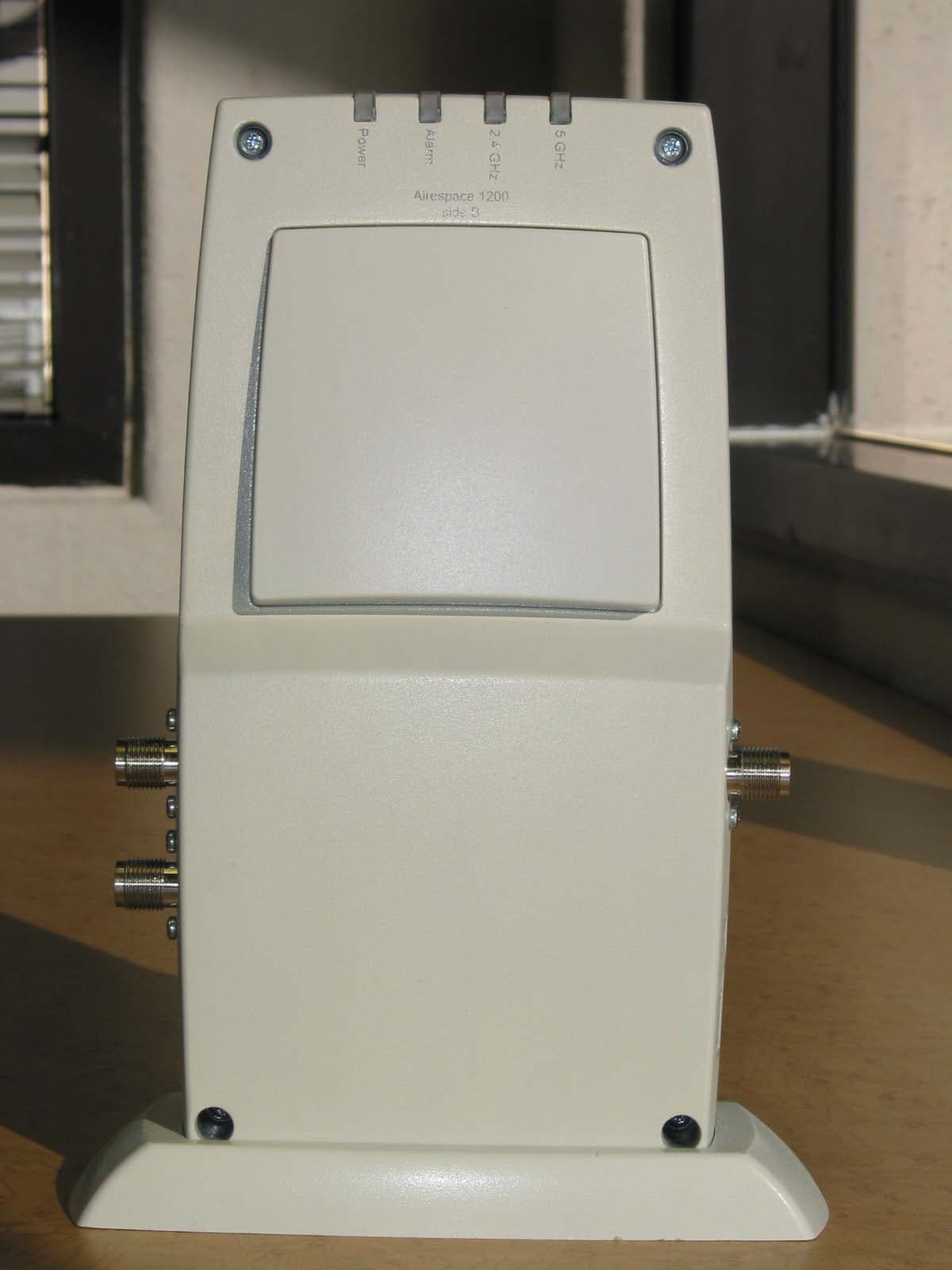
Click to zoom
Application Details
- Equipment Class
- DTS - Digital Transmission System
- Date of Grant
- Dec 17, 2003
- Application Purpose
- Original Equipment
- Date of Application
- Dec 17, 2003
- Equipment Note
- 2.4 GHz 802.11 Access Point
- Frequency Range
- 2412.00000000 - 2462.00000000
- Company
- Airespace
- Country
- United States
Documents & Files
Document Text
Text extracted from the exhibit documents filed with the FCC. Open a document above to read the original.
Users Manual
10/10/03© 2003 Airespace, Inc. All Rights Reserved. 90-100584-004 Welcome to the Airespace Product Guide!Airespace Product Guide Airespace System 1.2: Last Updated October 10, 2003 Refer to the OVERVIEWS section to see a big picture view of Airespace products and features. See the SOLUTIONS section to look through real-world network and application- specific solutions to real-world problems. Go to the TASKS section to find detailed instructions on how to install, configure, use, and troubleshoot Airespace products and supported 802.11 networks. Visit the REFERENCES section to see technical information, such as the Access Point Site Survey Guide, Quick Installation Guides, Web Browser Online Help files, and Release Notes. FCC Statements for Airespace Switches and Appliances FCC Statements for Airespace APs Legal Information Airespace Technical Support Airespace System Release Notes 10/10/03Legal Information 90-100584-004Airespace Product Guideii Legal InformationLegal Information This section includes the following legal information: •Limited Warranty •Software License Agreement •SSH Source Code Statement •OpenSSL Project License Statements •Trademarks and Service Marks 10/10/03Legal Information 90-100584-004Airespace Product Guideiii Limited Product WarrantyLimited Product Warranty The following describes the Airespace, Inc. standard Product Warranty for End Customers. ProductsProducts •Airespace Wireless Switch (40XX) Family •Airespace WLAN Appliance (41XX) Family •Airespace Access Point (1200) Family Limited WarrantyLimited Warranty Airespace warrants that: •For a period of one (1) year from the date of installation of the Product at the End Customer’s site but not to exceed twenty-four (24) months after date of shipment by Airespace, the Hardware shall free from defects in materials and workmanship. •For a period of three (3) months from the date of installation of the Product but not to exceed fifteen (15) months after date of shipment by Airespace, the Software shall substantially conform to the applicable specifications in Airespace’s then-current published documentation. The date of shipment by Airespace is set forth on the packaging material in which the Product is shipped. This limited warranty extends only to you the original purchaser of the Product. Exclusive RemedyExclusive Remedy Your sole remedy under the limited warranty described above is, at Airespace’s sole option and expense, the repair or replacement of the non-conforming Product or refund of the purchase price of the non-conforming Products. Airespace’s obligation under this limited warranty is subject to compli- ance with Airespace’s then-current Return Material Authorization (“RMA”) procedures. All replaced Products will become the property of Airespace. Exchange Products not returned to Airespace will be invoiced at full Product list prices. Replacement Products may be new, reconditioned or contain refur- bished materials. In connection with any warranty services hereunder, Airespace may in its sole discretion modify the Product at no cost to you to improve its reliability or performance. Warranty Claim ProceduresWarranty Claim Procedures Should a Product fail to conform to the limited warranty during the applicable warranty period as described above, Airespace must be notified during the applicable warranty period in order to have any obligation under the limited warranty. The End Customer or their designated reseller must obtain a Return Material Authorization number (RMA number) from Airespace for the non-conforming Product and the non-conforming Product must be returned to Airespace according to the then-current RMA procedures. The End Customer or their designated reseller is responsible to ensure that the shipments are insured, with the transportation charges prepaid and that the RMA number is clearly marked on the outside of the package. Airespace will not accept collect shipments or those returned without an RMA number clearly visible on the outside of the package. Exclusions and RestrictionsExclusions and Restrictions Airespace shall not be responsible for any software, firmware, information or memory data contained in, stored on or integrated with any Product returned to Airespace pursuant to any warranty or repair. Upon return of repaired or replaced Products by Airespace, the warranty with respect to such Products will continue for the remaining unexpired warranty or sixty (60) days, whichever is longer. Airespace may provide out-of-warranty repair for the Products at its then-prevailing repair rates. 10/10/03Legal Information 90-100584-004Airespace Product Guideiv The limited warranty for the Product does not apply if, in the judgment of Airespace, the Product fails due to damage from shipment, handling, storage, accident, abuse or misuse, or it has been used or maintained in a manner not conforming to Product manual instructions, has been modified in any way, or has had any Serial Number removed or defaced. Repair by anyone other than Airespace or an approved agent will void this warranty. EXCEPT FOR ANY EXPRESS LIMITED WARRANTIES FROM AIRESPACE SET FORTH ABOVE, THE PRODUCT IS PROVIDED “AS IS”, AND AIRESPACE AND ITS SUPPLIERS MAKE NO WARRANTY, EXPRESS, IMPLIED, STATUTORY OR OTHERWISE, WITH RESPECT TO PRODUCT OR ANY PART THEREOF, INCLUDING WITHOUT LIMITATION ANY IMPLIED WARRANTY OF TITLE, MERCHANTABILITY, FITNESS FOR A PARTICULAR PURPOSE, NON-INFRINGEMENT, OR THOSE ARISING FROM COURSE OF PERFORMANCE, DEALING, USAGE OR TRADE. AIRESPACE’S SUPPLIERS MAKE NO DIRECT WARRANTY OF ANY KIND TO END CUSTOMER FOR THE LICENSED MATERIALS. NEITHER AIRESPACE NOR ANY OF ITS SUPPLIERS WARRANT THAT THE LICENSED MATERIALS OR ANY PART THEREOF WILL MEET END CUSTOMER'S REQUIREMENTS OR BE UNINTERRUPTED, OR ERROR-FREE, OR THAT ANY ERRORS IN THE PRODUCT WILL BE CORRECTED. SOME STATES/JURISDICTIONS DO NOT ALLOW THE EXCLUSION OF IMPLIED WARRANTIES SO THE ABOVE EXCLUSIONS MAY NOT APPLY TO END CUSTOMER. THIS LIMITED WARRANTY GIVES…
Text truncated - open the document above for the full version.
Cover Letter(s)
November 26, 2003 TO: Mr. Tim Johnson American Telecommunications Certification Body Inc. 6731 Whittier Ave, McLean, VA 22101 RE: Airespace FCC ID: QTZWN1200BG Tim, Below are the replies to your inquiries regarding this application. If something is unclear, or if you have additional concerns, please contact me. Best Regards, David Waitt Consultant representing Airespace [email protected] ATCB 1) The internal photographs appear to show that 2 cards are internally installed, instead of just one as specified by this application. Please correct. Airespace ) The incorrect set of photos was uploaded inadvertently. New photos have been uploaded to the ATCB site. ATCB 2) Since this is a 802.11b/g version product only, please remove reference to the 5 GHz testing given on page 6. Airespace ) The reference has been deleted. ATCB 3) Based on how information was presented in the report, the RF exposure calculations incorrectly take into consideration the RF switch. Please correct the RF exposure calculations Airespace ) The calculation has been corrected.. The power level into the antenna was correct. However the antenna gain was 1 dB to low. This has been corrected. A revised calculation has been uploaded to the ATCB site ATCB 4) The spectral density table appears to be incorrectly labeled as only 802.11b results appear to be shown. Please correct. Airespace ) The table has been corrected. ATCB 5) Please provide a justification for the device as a Class A device. Airespace ) A letter outlining Class A justification has been uploaded to the ATCB site ATCB 6) The transmit band is incorrectly reported on page 23, please correct. Airespace ) The error has been corrected. ATCB 7) The conducted emissions state that they device was tested from 150 kHz to 30 MHz using the new EN55022 harmonized limits. However, the limits specified do not equate to any known limit. The results shown are only around 25-30 MHz. Please confirm the frequency range tested and the limits applied. Note that limits specified by 15.207 are equivalent to Class B limits. Also, the device must meet both Average and QP limits, while some emissions shown exceed the average limits. Please correct as necessary. Airespace ) A more complete presentation of the AC line conducted emissions is contained in the report. The highest peak emissions were all within the narrow frequency range of 25 to 30 MHz. 110 Nortech Parkway San Jose, CA, 95134 (408) 635 2000 www.airespace.com ATCB 8) Given that the device may accept an AC adapter or POE power according to the users manual, the AC line conducted emissions should be checked to determine which method of supplying power is worse case. Only one set of data appears to be provided. Please provide further information regarding whether both modes of providing power were checked to ensure the worse case results are provided. Airespace ) A more complete presentation of the AC line conducted emissions has been added to the report. The Access point radio has been tested when powered by the AC adapter and the power over Ethernet from the Ethernet switch. This was, of course, necessary in order to verify Class A compliance of the Ethernet switch. In general, the AC line conducted emissions results presented are worst case levels. This is due in part to the additional filtering that is incorporated into the power supply within the Ethernet switch. ATCB 9) A justification for not requiring external antenna measurements was provided. However neither data sheets or technical information has been provided to compare these antennas, their types, gains, patterns, etc. and other specifications. Please provide. Alternatively, please provide test data for the external antennas. Note that the test report mentions that the unit was not tested with external antennas, however they are shown in the test photographs. Additionally, information regarding the external antenna should be included in the RF exposure exhibit. Please explain. Airespace ) The pictures and data sheets of the external antennas was inadvertently omitted. A document containing pictures and data sheets of the antennas has been uploaded to the ATCB site. Note that the external antennas were not tested for this application due to the fact that they are the same type of antenna (“patch”), and lower gain than the access point internal antenna. ONLY the external 3 dBi and 5 dBi versions of the external antennas are available for use with the access point and both of these antennas has lower gain then the internal antenna. Therefore the internal antenna represents the worst case scenario. ATCB 10) Previous applications provided an attestation letter regarding the upgrade feature of this radio. Please provide a similar letter and/or upgrade manual for this application. Airespace ) A letter outlining the upgrade process will be uploaded to the ATCB site as soon as possible. ATCB 11) The external photographs appear to show standard screws for the access door which contradicts the information given in previous upgrade manuals stating special Torx screws are used. Please comment. Airespace ) The unit that was used for testing incorporated regular Phillips screws simply for ease of assembly / disassembly and the fact that Phillips screwdrivers are ubiquitous. Security Torx screws are used in the units that are sold to customers. ATCB 12) Please provide additional close up photographs of the external antennas. Airespace ) Additional pictures of the external antennas are included in the file “External_2_4GHz_ant_data_pix.pdf” that has been uploaded to the ATCB site.
Cover Letter(s)
To: Federal Communications Commission 7435 Oakland Mills Road Columbia, Maryland 21046 Subject: Authorization of David Waitt to act on our behalf and as our agent for preparation of FCC certification applications. Gentlemen, This is a letter of authorization to accept David Waitt, an independent consultant who’s services have been retained by Airespace to sign applications before the commission on our behalf, to make representations to you on our behalf and to receive and exchange data between our company and the Commission in connection with the certification of the following product(s): FCC ID: QTZAM1200ABG FCC ID: QTZWN1200BG FCC ID: QTZWN1200ABG Under FCC Docket number 20780 and General Docket Number 80-284 pursuant to Part 15 of the FCC Rules and Regulations. If you have any further questions or need additional information, please feel free to contact me at [email protected] <Orig Signature on File> Nov 2003 Bob Friday Airespace, Date Sr. Scientist 110 Nortech Parkway San Jose, CA, 95134
Cover Letter(s)
To: Federal Communications Commission From: Airespace Subject: Justification for Class A classification of the following FCC IDs QTZAM1200ABG QTZWN1200BG QTZWN1200ABG Date: Nov 29 2003 Gentlemen, The purpose of this letter is to provide justification for classifying the above products as Class A. All of the devices are a IEEE802.11 A/BG or 802.11 B/G access points. The Airespace Access Point must be controlled and monitored by an Airespace Ethernet switch product. The Airespace AP1200 series of products (and its associated 24 port Ethernet switch) is intended only for industrial / corporate environments. Marketing of the products will not be targeted at individuals for residential use. The Airespace products are intended for use in corporate and industrial environments. The AP1200 will not be available for purchase at consumer oriented retail outlets. If any further information is required, please do not hesitate to contact me at the email address below. David Waitt Consultant representing Airespace [email protected]
Cover Letter(s)
To: Federal Communications Commission 7435 Oakland Mills Road Columbia, Maryland 21046 Subject: Confidentiality Request for Certification Application Gentlemen, On behalf of Airespace, I request that the following documents: • Any/All circuit schematics. • Any/All electrical block diagrams • Any/All parts lists • Associated with the following Part 15 Certification applications: • FCC ID: QTZ-AMAP1200ABG • FCC ID: QTZ-WN1200ABG • FCC ID: QTZ-WN1200BG be withheld from public disclosure per Section 0.459 of the FCC Rules. This request is made under the provisions of Section 0.457(d) of the FCC rules and Sections 552(b)(4) of the Freedom of information Act. These Sections authorize withholding from public inspection, materials which would be privileged as a matter of law if retained by the person submitting them in addition to materials, which would not customarily be released to the public, by that person. If you have any questions, please do not hesitate to contact me at: [email protected] or (408) 832-7053 Sincerely, David Waitt Consultant representing Airespace 110 Nortech Parkway San Jose, CA, 95134
Cover Letter(s)
13 Dec , 2003 TO: Mr. Tim Johnson American Telecommunications Certification Body Inc. 6731 Whittier Ave, McLean, VA 22101 RE: Airespace FCC ID: QTZWN1200BG Tim, Below are the replies to your inquiries regarding this application. If something is unclear, or if you have additional concerns, please contact me. Best Regards, David Waitt Consultant representing Airespace [email protected] ATCB 1) The values listed for power on page 22 of the 802.11b/g report appears lower than the measured power. Please provide an explanation. Airespace: This is simply a function of number of points on the trace of the spectrum analyzer and the span of the sweep. Assuming there are finite number points in the spectrum analyzer sweep, with a span of 23970MHz, a trace point may not fall on the peak of the carrier. Thus, fundamental appears lower than it actually is. ATCB 2) Please provide an explanation of the high emissions seen below the fundamental on page 23 of the 802.11b/g report. This emissions could be seen as above the limit. Airespace: This is an artifact of the spectrum analyzer. It is the “zero frequency” of the spectrum analyzer. ATCB 3) The bandedge plots do not appear to follow the method given. Please review and adjust as necessary. (see QTZWNAP1200B) Airespace: The Bandedge measurements for 802.11 G have been adjusted. The 802.11 B measurements remain the same was used in previous Airespace B applications. The 802.11 G band edge presents the worst case results. In the future, Plots for the data for the ‘B’ mode of operation will reflect the provided test procedure. ATCB 4) Please note that radiated emissions in restricted bands are considered to be any emission caused by the transmitter being turned on, not strictly the harmonics. This includes such emissions as LO's, intermod products, frequencies as part of any multiplication stages, etc. However radiated emissions only appear to be performed for > 4800 MHz. Airespace: No emissions were noticeable above 12 GHz. The entire frequency range was scanned (above 1 GHz); however, the only significant emissions during the radiated tests appeared to be harmonics of the fundamental. 110 Nortech Parkway San Jose, CA, 95134 (408) 635 2000 www.airespace.com
External Photos
External Product Photos Airespace Access Point. Model: 1200 FCC Part 15 Certification Application Prepared by: David Waitt 202 Calvert Drive #217 Cupertino, Ca. 95014 [email protected] (408) 832 7053 110 Nortech Parkway San Jose, California, 95134 Airespace 1200, Side B Airespace 1200, Side A Airespace 1200, Alarm Indicators The 5GHz Reverse TNC External connector, (Currently not certified for use and disabled) and one of the reverse TNC external antenna connector for 2.4 GHz Airespace 1200, Bottom Airespace 1200, Top
ID Label/Location Info
To: Office of Engineering and Technology Federal Communications Commission 445 12TH ST SW Washington DC 20554 Re: FCC ID: QTZ-WN1200BG Certification Application. Regulatory Compliance Label Drawing Gentlemen, The label shown below will appear on the Airespace Access point and will be located on the bottom of the unit as shown. 110 Nortech Parkway San Jose, CA, 95134
Internal Photos
Internal Product Photos Airespace Model: 1200 802.11 B/G Access Point FCC ID: QTZWN1200BG FCC 15.247 Certification Application Prepared by: David Waitt 202 Calvert Drive #217 Cupertino, Ca. 95014 [email protected] (408) 832 7053 110 Nortech Parkway San Jose, California, 95134 Model 1200 BG Accesspoint, Side A, Internal Model 1200 B/G accesspoint, B side, internal Model 1200 B/G access point. A side antennas Left (2.4 GHz) Right (5 Ghz - Unused) Model 1200 B/G access point. B side antennas Right (2.4 GHz) Left (5 Ghz - Unused) 802.11 module, shields removed 802.11 module, shields removed, rear
Operational Description
Addendum to EMI Test Report and Technical Documentation on Airespace Access Point. Model: 1200 2.4 GHz External Antenna(s) Pictures and data sheets Prepared by: David Waitt 202 Calvert Drive #217 Cupertino, Ca. 95014 [email protected] (408) 832 7053 110 Nortech Parkway San Jose, California, 95134 Features: Specifications: Element Type Air-Loaded Patch Frequency Range 2400-2500 MHz Peak Gain 3 dBi Polarization 1 Linear Impedance 50 ohms Maximum Input Power 50 watts VSWR (Min. Performance) 1.5:1 Connector Customer Choice Dimensions (cm) 6.4 x 6.3 x 1.7 cm Housing Coating Material ABS Operating Temperature -40º to +70ºC Storage Temperature -40º to +70ºC Includes a low-loss, RG 142, plenum rated “pigtail” cable. 1 Contains both vertical and horizontal components, the ratio of which varies with the spatial location. Cables & Connectors: Part Number Cable Connector CAF94101 12” RG-142 Plenum Rated Coax SMA-Male CAF94170 12” RG-142 Plenum Rated Coax N-Female CAF94150 36” RG-142 Plenum Rated Coax RP-TNC CAF94144 36” RG-142 Plenum Rated Coax RP-TNC 2400 MHz Sphere Part Number (P/N): CAF94101 CAF94170 CAF94150 CAF94144 2400 MHz Sphere – 10/30/02 Omnidirectional Antenna Omnidirectional antenna provides a considerable gain improvement over traditional dipole antennas, within a remarkably small case that perfectly blends into any environment. It is particularly applicable in environments such as offices and hospitals, where aesthetics are critical to successful wireless deployment and wide angle coverage is necessary. For easy installation, the Sphere quickly attaches to a ceiling tile frame with a standard metal clip. Azimuth Plane Cut perpendicular to the antenna and perpendicular to the cable Elevation Plane Cut perpendicular to the antenna alon g the cable axis Omni Plane Cut in the plane of the antenna parallel to the cable Sphere 2400 Xertex Products Reliability Without the Expense... FEATURES & OPTIONS: In-Building Reliable coverage is always a priority in streamlining the effectiveness of wireless devices. This is especially crucial in commercial, office, campus and residential environments that strive to cover a multitude of users in an open space or long corridor. Centurion’s Whisper directional and Terrace bi-directional antennas offer an affordable option for in-building antenna systems. Our innovative designs blend into any atmosphere and provide excellent coverage in high traffic areas. WHI SPER - Directional Antenna • Self contained in a durable sleek radome, the Whisper is designed to blend in anywhere - residential, campus or commercial • Inexpensive yet reliable, the Whisper utilizes Centurion's patented technology to achieve maximum efficiency. • Typical applications include wireless local loop, in-building wireless (voice and data), WLAN, DECT, WPBX, and broadband Internet access. TERRACE - Bi-directional Antenna • Utilizes a patented low-profile design to provide coverage in corridors or long hallways • Provides outstanding performance in healthcare and office environments, where a long hallway presents a design or coverage challenge DIRECTIONAL/BI-DIRECTIONAL ANTENNAS AntennasA www.centurion.com Telematics 802.11/Bluetooth In-Building Mobile Phones LMR Power Specifications subject to change without notice Copyright © 2001 Centurion Wireless Technologies, Inc. All Rights Reserved www.centurion.com 3425 N.44th St., LINCOLN, NE 68504 USA SALES PHONE 800.228.4563 • SALES FAX 800.826.3774 INTERNATIONAL PHONE 402.474.0706 • FAX 402.467.4528 In-Building DIRECTIONAL/BI-DIRECTIONAL ANTENNAS All centurion products are designed for maximum efficiency and are customizable and scalable to meet your frequency and application requirements. SPECIFICATIONS: PATTERNS: As displayed in these typical patterns, In-Building Directional and Bi- Directional antennas offer superior high-gain reception over a broad area. General specifications for In-Building Directional and Bi-Directional Antennas: ELEMENT TYPE Air-Loaded Patch FREQUENCY RANGE 806-2500 MHz PEAK GAIN 5.0-9.0 dBi POLARIZATION 1 Linear IMPEDANCE 50 ohms MAXIMUM INPUT POWER 50 watts FRONT/BACK RATIO 18-20 dBi VSWR (MIN. PERFORMANCE) 1.5:1-2.0:1 RADOME MATERIAL (INDOOR) ABS or Luran RADOME MATERIAL (OUTDOOR) Kydex 2 or Luran 2 1 Polarization axis is parallel to the cable axis, or along the long axis of the antenna for models without cable pigtails. 2 UV tolerance rated to 7 years of outdoor exposure. AZIMUTH PLANE cut perpendicular to the antenna and perpendicular to the cable ELEVATION PLANE cut perpendicular to the antenna along the cable axis OMNI PLANE Spherical Projection AZIMUTH PLANE cut perpendicular to the antenna and perpendicular to the cable ELEVATION PLANE cut perpendicular to the antenna along the cable axis OMNI PLANE cut perpendicular to the antenna along the cable axis TYPICAL WHISPER ANTENNA PATTERNS TYPICAL TERRACE ANTENNA PATTERNS Elevation Azimuth Centurion 2.4 GHz 3dBi (#94150) antenna Centurion 2.4 GHz 5dBi (#94149) antenna
RF Exposure Info
Mobile Power Density Calculation for FCC ID: QTZ-WN1200BG The Airespace Access Point (AP) is an IEE802.11 B /G radio. The access point operates on the 2.4 GHz ISM band. Note that the access point cannot transmit B and G at the same time. Operating Environment: The operating environment for the for the radio in all cases is a fixed, uncontrolled environment, however, the devices are classified as being “Mobile”, Therefore the exposure at 20 cm is calculated. Fixed, Uncontrolled Environment: The FCC limit for the power density for uncontrolled exposure to RF devices operation at 2.4GHz and 5GHz at a distance of 20 cm is: 1 mW/cm 2 Power density is calculated from the following equation Exposure (mW/cm 2 ) = EIRP(mW) * Duty Cycle 4*PI* Radius 2 (cm) Where: Radius = 20 cm Duty Cycle = assumed to be 100% to yield a worst case result. 2.4GHz ISM Band MPE distance Calculation Using the highest power measured on the 2.4 GHz ISM band. MAX Pout: 20.4 dBm (109.65 mW) MAX Ant Gain 7.8 dBi (6.02x) EIRP: 28.2 dBm (660.69 mW EIRP) Calculating power density at a distance of 20 cm yields: Delta = specification - result 1 mW/cm 2 - .13144 mw/cm 2 = .86856 mw/cm 2 = 8.812 dB 660.69 5026.54 660.69 * 1 4 * Pi * 20 2 Power = Density .13144mW/cm 2 110 Nortech Parkway San Jose, California, 95134
Test Report
EMI Test Report and Technical Documentation on Airespace Virtual Access Point. Model: 1200 FCC ID: QTZWN1200BG 110 Nortech Parkway San Jose, CA, 95134 (408) 635 2000 www.airespace.com FCC Part 15.247 Certification Application Industrie Canada RSS210 Certification Prepared by: David Waitt 202 Calvert Drive #217 Cupertino, Ca. 95014 [email protected] (408) 832 7053 Airespace FCC Part 15 Certification Application Table of Contents Section Page General information------------------------------------------ 3 Detailed product information--------------------------------- 4 Results summary---------------------------------------------- 5 Test facilities---------------------------------------------- 6 Test Equipment----------------------------------------------- 7 Test methods------------------------------------------------- 8 Test Results Maximum power at RF Output------------------------------ 10 6dB Bandwidth------------------------------------------- 13 Power spectral density---------------------------------- 17 Out of band emissions ---------------------------------- 21 Radiated emissions in restricted bands------------------ 23 Radiated emissions in restricted bands (band edge)------ 26 AC Line conducted Emissions ---------------------------- 31 Airespace FCC Part 15 Certification Application Unit(s) Under Test: Airespace Access Point (AP) Model: 1200 Product Description: IEEE 802.11 B Access point FCC ID: QTZWN1200BG Tested For: Airespace 110 Nortech Parkway San Jose, Ca. 95134 Tested At: Elliott Laboratories 684 West Maude Ave Sunnyvale, CA 94086 Tested By: Juan Martinez, Sr. Test Engineer, Elliott Laboratories Chris Byleckie, Test Engineer, Elliott Laboratories Trinh Waitt, (Independent Consultant for Airespace) Test Specifications: FCC CFR 47, Part 15.247, 2.4 GHz DSSS Test Date: March 2003 / Nov 2003 Requested Certification: Part 15.247 Certification General Information Airespace FCC Part 15 Certification Application The Airespace radio is an IEEE 802.11 B/G Access point (AP) intended to be professionally installed and configured in corporate and industrial environments. The device utilizes a mini PCI module manufactured by an outside vendor. The manufacturer of the module has received FCC modular approval. The Airespace access point uses the module with a higher gain antenna than was certified for use with the module, therefore Airespace is applying for their own grant. The AP utilizes integral antennas on the 802.11 B/G band. The access point effectively includes only a single 2.4GHz patch antenna, however, there are actually two 2.4 GHz antennas. The module switches rapidly between the two antennas and when a signal is detected, the access point uses the antenna offering the best transmission characteristics. At any one time, there is only one antenna connected to the internal PCI module. Certification of external “patch” antennas is also being requested as part of this certification application. The gain of the external antennas is less than that of the internal antennas, so the unit was tested only with the internal antennas. The effective gain of the 2.4 GHz internal antenna path (the antenna switch and the antenna itself) is 6.8dBi. The diagrams below outline the RF path from the output of the mini PCI module to the integral antennas within the access point. Detailed Product Information Airespace FCC Part 15 Certification Application This report presents the results of the tests that verify compliance with FCC Part 15.247.. A brief results summary of all the in this report is below. Part 15 RSS-210 Paragraph Paragraph Test Results 15.247(b) 6.2.2(o)(a) 3 Maximum Power Output (802.11 B) 20.4 dBm Max 15.247(b) 6.2.2(o)(a) 3 Maximum Power Output (802.11 G) 20.4 dBm Max 15.247(a)(2) 6.2.2(o)(e1) 6dB Bandwidth (802.11 B) 12.00 MHz Min 15.247(a)(2) 6.2.2(o)(e1) 6dB Bandwidth (802.11 G) 16.83 MHz Min 15.247(d) 6.2.2(o)(d1) Power Spectral Density (802.11 B) -12.96dBm/3kHz Max 15.247(d) 6.2.2(o)(d1) Power Spectral Density (802.11 G) -13.00dBm/3kHz Max 15.247(c) 6.2.2(o)(a) 4 Out of Band Spurious Emissions -44 dBc Max 15.205 6.3( c ) Radiated Emissions in Restricted bands .36 dB in spec min @2390 MHz (802.11 G) Test Results Summary Airespace FCC Part 15 Certification Application Many of the certification tests were performed at: Elliott Labs 684 West Maude Ave Sunnyvale, CA 94086 The tests performed at Elliott include: • All radiated emissions tests required in FCC Part 15.205 for 2.4 GHz. • Out of band emissions (Conducted) (for 2.4 GHz) General: Final 802.11 B radiated test measurements were taken in March 2003 at the Elliott Laboratories Open Area Test Site #4. The test site contains separate areas for radiated and conducted emissions testing. Pursuant to section 2.948 of the Rules, construction, calibration, and equipment data has been filed with the Commission. The FCC recommends that ambient noise at the test site be at least 6 dB below the allowable limits. Ambient levels are below this requirement with the exception of predictable local TV, radio, and mobile communications traffic. The test site contains separate areas for radiated and conducted emissions testing. Considerable engineering effort has been expended to ensure that the facilities conform to all pertinent FCC…
Text truncated - open the document above for the full version.
Contact Information
Applicant
Bob Friday(Sr. Scientist)
Technical Contact
ConsultantDavid Waitt
[email protected]408-832-7053
202 Calvert Drive · Cupertino, California · United States
Non-Technical Contact
ConsultantDavid Waitt
[email protected]408-832-7053
Test Firm
Elliott Laboratories LLCDavid Bare
Technical Specifications
| # | Rule Parts | Frequency Range | Power Output |
|---|---|---|---|
| 1 | 15C | 2.41 GHz - 2.46 GHz | 110.00 mW |
Other Applications from Airespace
QTZ1300
Mar 30, 2005Outdoor Access Point
Equipment Class
DTS - Digital Transmission System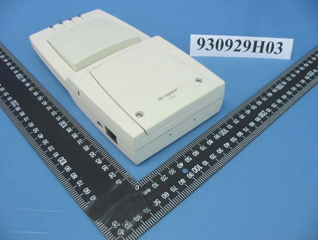
QTZ1200D
Dec 16, 2004IEEE 802.11 a/g Wireless LAN Access Point
Equipment Class
NII - Unlicensed National Information Infrastructure TXQTZ1200W
Jun 19, 2004802.11 Dual Band Access Point
Equipment Class
DTS - Digital Transmission System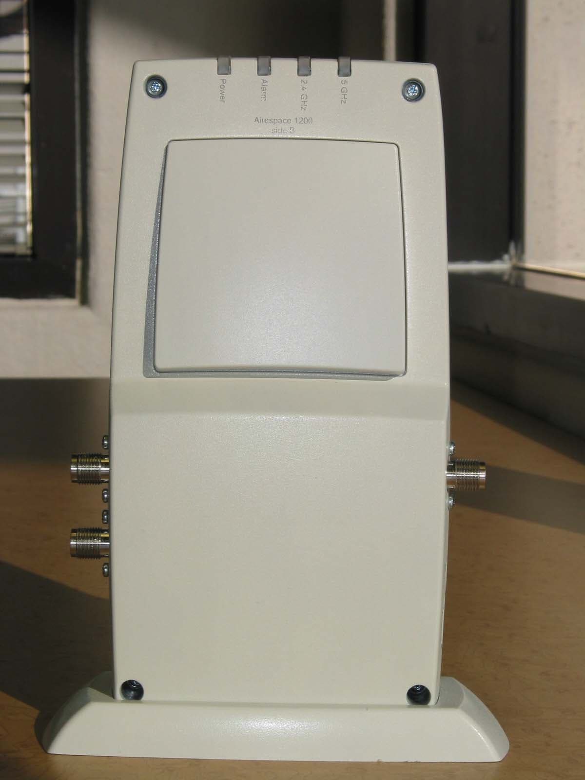
QTZAM1200ABG
Jan 12, 2004802.11 Dual Band Access Point
Equipment Class
DTS - Digital Transmission System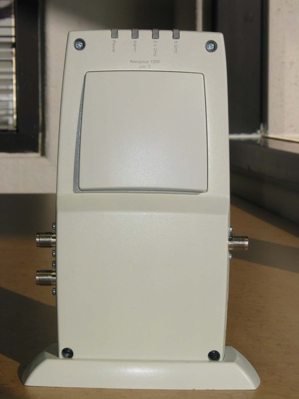
QTZAMAP1200AB
Nov 04, 2003802.11 Dual Band Access Point
Equipment Class
DTS - Digital Transmission System