QTZUSAP1200A802.11A Access Point
Airespace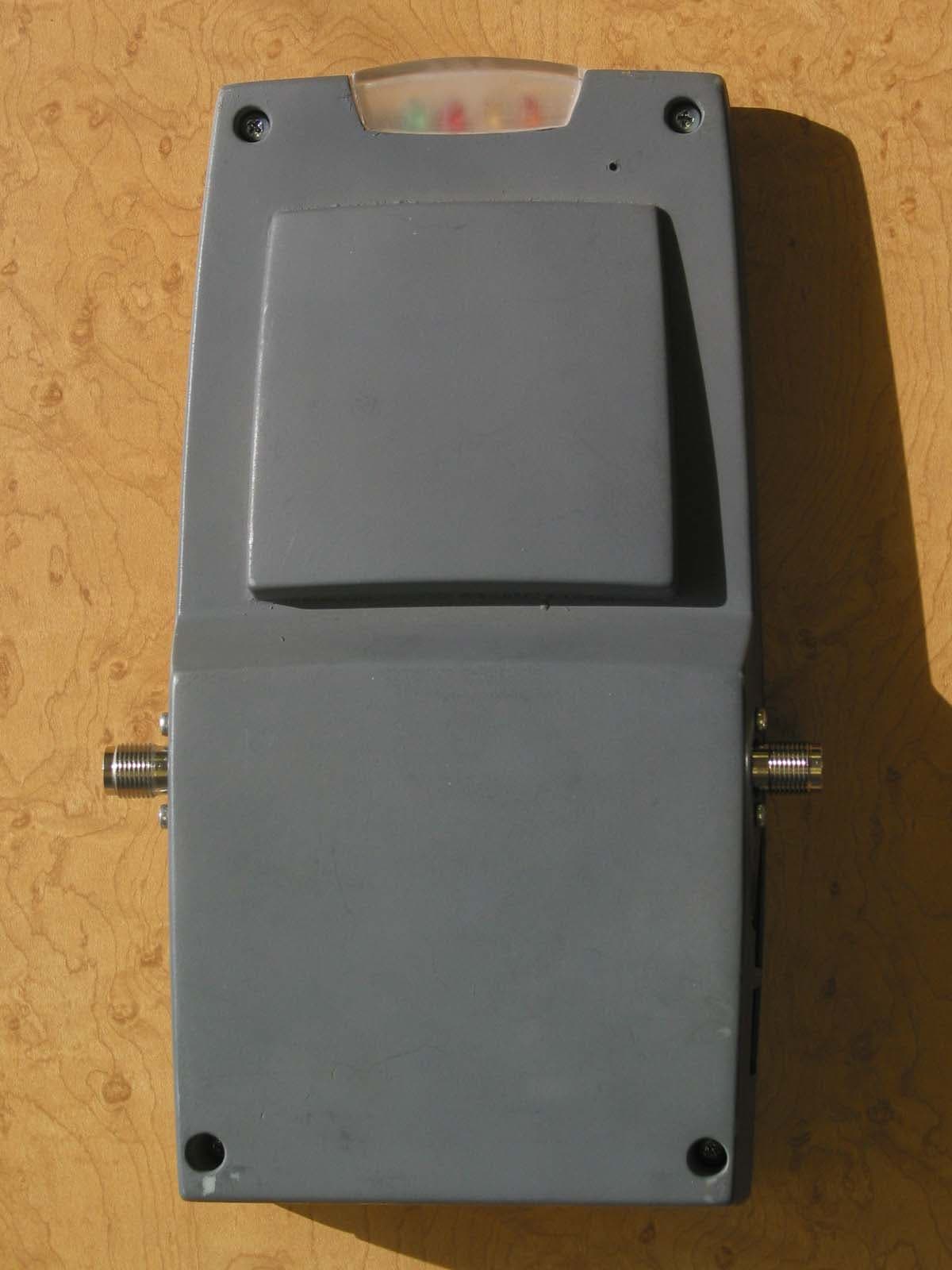
Click to zoom
Application Details
- Equipment Class
- NII - Unlicensed National Information Infrastructure TX
- Date of Grant
- Apr 03, 2003
- Application Purpose
- Original Equipment
- Date of Application
- Mar 23, 2003
- Equipment Note
- 802.11A Access Point
- Frequency Range
- 5745.00000000 - 5805.00000000
- Company
- Airespace
- Country
- United States
Documents & Files
Document Text
Text extracted from the exhibit documents filed with the FCC. Open a document above to read the original.
Users Manual
Copyright © 2003 Airespace, Inc. All Rights Reserved. 1 Airspace Access Point (AP) Installation Guide Airespace System 1.0: March 17, 2003 Airespace, Inc. 110 Nortech Parkway San Jose, CA 95134 1-408-635-2000 www.airespace.com Copyright © 2003 Airespace, Inc. All Rights Reserved. 2 Legal Information Disclaimer Airespace™ and Airespace AP™ are trademarks of Airespace, Inc. All other trademarks, service marks, and product names used in this document are the property of their respective owners. U.S.A. Government Restricted Rights (tbd) Applicable Laws (tbd) Copyright © 2003 Airespace, Inc. All Rights Reserved. 3 FCC Statements This equipment has been tested and found to comply with the limits for a Class A digital device, pursuant to Part 15 of the FCC Rules. These limits are designed to provide reasonable protection against harmful interference when the equipment is operated in a commercial environment. This equipment generates, uses, and can radiate radio frequency energy and, if not installed and used in accordance with the instruction manual, may cause harmful interference to radio communications. Operation of this equipment in a residential area is likely to cause harmful interference in which case the user will be required to correct the interference at his own expense. RF Radiation Hazard Warning To ensure compliance with FCC RF exposure requirements, this device must be installed in a location such that the antenna of the device will be greater than 20 cm (8 in.) from all persons. Using higher gain antennas and types of antennas not covered under the FCC certification of this product is not allowed. Note: No 802.11a external antennas are currently certified or available in this release. Contact Airespace, Inc. for a list of FCC-approved 802.11b external antennas. Installers of the radio and end users of the system must adhere to the installation instructions provided in this manual. Non-Modification Statement Use only the supplied internal antenna, or external antennas supplied by the manufacturer. Unauthorized antennas, modifications, or attachments could damage the badge and could violate FCC regulations and void the user’s authority to operate the equipment. Copyright © 2003 Airspace, Inc. All Rights Reserved. 4 Table of Contents Airspace Access Point (AP) Installation Guide 1 Legal Information 2 Disclaimer 2 Trademarks and Service Marks 2 U.S.A. Government Restricted Rights 2 Applicable Laws 2 FCC Statements 3 RF Radiation Hazard Warning 3 Non-Modification Statement 3 Table of Contents 4 About this Guide 5 About the Airespace Access Point 6 About Airespace AP Models and Upgrade Card 9 About the Airespace AP 802.11a Radio Card 10 About Internal and External Airespace AP Antennas 11 About Airespace AP LEDs 12 About Airespace AP Connectors 13 About Airespace AP Physical Security 14 About Power Over Ethernet 15 Installing Airespace APs 16 Planning Airespace AP Locations 17 Mounting Airespace APs 18 Copyright © 2003 Airespace, Inc. All Rights Reserved. 5 About this Guide The Airespace Access Point (AP) Installation Guide allows installation planners, network administrators, and installers to work together to install Airespace APs in a target environment. Refer to the following sections for more information about the Airespace AP. Copyright © 2003 Airespace, Inc. All Rights Reserved. 6 About the Airespace Access Point The Airespace AP is a part of the innovative Airespace System. When associated with an Airespace 4000 Switch as shown in the following figure, the Airespace AP provides advanced 802.11a and/or 802.11b AP functions in a single sleek enclosure, including unmatched scalability and security solutions for enterprises and Wireless ISPs. In the Airespace System, most of the processing power is removed from a traditional AP to the Airespace Switch. Airespace Switch and APs Copyright © 2003 Airspace, Inc. All Rights Reserved. 7 The following figure shows an Airespace AP with the optional ceiling mount base. Airespace AP with Ceiling Mount Base Refer to the following for more information on Airespace APs: • Airespace AP Models • Airespace AP 802.11a Radio Cards • Internal and External Airespace AP Antennas • About Ethernet Cabling • Airespace AP LEDs • Airespace AP Connectors • Airespace AP Power Requirements • Airespace AP External Power Converter • About Power Over Ethernet (PoE) • Airespace AP Physical Security • Airespace AP Automatic Software Upgrades • Airespace AP Specifications • Installing Airespace APs Copyright © 2003 Airspace, Inc. All Rights Reserved. 8 Copyright © 2003 Airespace, Inc. All Rights Reserved. 9 About Airespace AP Models and Upgrade Card The Airespace AP includes one 802.11a radio (1200A), one 802.11b radio (1200B), or one 802.11a and one 802.11b radio (1200AB). As an added feature, the 1200B Airespace AP can be updated by the customer with an 802.11a radio, allowing for current 802.11b coverage and future 802.11a coverage by the same Airespace AP. Refer to the Airespace AP 802.11a Radio Card section for information on the field-installable radio that adds 802.11a capability to an existing 802.11b Airespace AP. The Airespace AP comes in the following configurations: • Model 1200A - Airespace AP with one 802.11a radio and two high-gain internal antennas • Model 1200B - Airespace AP with one 802.11b radio and four high-gain internal antennas; can be upgraded to a 1200AB by adding an 802.11a Radio Card • Model 1200AB - Airespace AP with one 802.11a and one 802.11b radio and four high-gain internal antennas The following upgrade card is also available: • 802.11a Radio Card - Add this card to a 1200B to create a 1200AB Airespace AP The Airespace AP is shipped with a color-coordinated ceiling mount base, and projection and flush wall mount brackets. These brackets and base allow quick mounting to ceiling, wall or pole: • Ceiling Mounting Kit - Allows you to mount the Airespace AP on any horizontal surface • Flush Wall Mount Kit - Allows you to mount the Airespa…
Text truncated - open the document above for the full version.
Cover Letter(s)
To: Mr. Tim Johnson, American TCB From: David Waitt, Airespace Subject: Inquiries regarding Certification application for FCC ID QTZUSAP1200A Date: 24 March 2003 Tim, Below are the replies to your inquiries regarding this application. The answers are numbered corresponding to your inquiries in your letter dated 24 March 2003. If something is unclear, or if you have additional concerns, please contact me. Best Regards, David Waitt Consultant representing Airespace ATCB 1) The BOM contains 2 RF TX Cards. This device only contains 1 TX card. Please explain. Airespace: This was an error. The BOM for the dual band product containing two cards was inadvertently submitted. The correct BOM has been uploaded to the ATCB site. ATCB 2) Please provide a schematic for this device. The schematic provided only contained a block diagram. Airespace: A more detailed schematic has been uploaded to the ATCB site. ATCB 3) Please provide a users manual for this device. This manual must include appropriate FCC statements and RF exposure information. Airespace: The manual was accidentally omitted from the original application. It has been uploaded to the ATCB site.
Cover Letter(s)
American Telecommunications Certification Body Inc. 6731 Whittier Ave, McLean, VA 22101 March 24, 2003 RE: Airespace FCC ID: QTZUSAP1200A I have a few comments on the above referenced Application. 1) The BOM contains 2 RF TX Cards. This device only contains 1 TX card. Please explain. 2) Please provide a schematic for this device. The schematic provided only contained a block diagram. 3) Please provide a users manual for this device. This manual must include appropriate FCC statements and RF exposure information. Timothy R. Johnson Examining Engineer mailto: [email protected] The items indicated above must be submitted before processing can continue on the above referenced application. Failure to provide the requested information may result in application termination. Correspondence should be considered part of the permanent submission and may be viewed from the Internet after a Grant of Equipment Authorization is issued. Please do not respond to this correspondence using the email reply button. In order for your response to be processed expeditiously, you must submit your documents through the AmericanTCB.com website. Also, please note that partial responses increase processing time and should not be submitted. Any questions about the content of this correspondence should be directed to the sender.
Cover Letter(s)
To: Mr. Tim Johnson, American TCB From: David Waitt, Airespace Subject: FCC ID QTZVAP1200 compliance with FCC Part 15.407 (c),(d),(e),(g) Date: 10 Feb 2003 This letter attests to the compliance of the VAP1200 to the below referenced FCC specifications. If there are any questions or if additional information is required, please contact me at [email protected] On behalf of Airespace, David Waitt 15.407 (c) The device shall automatically discontinue transmission in case of either absence of information to transmit or operational failure. These provisions are not intended to preclude the transmission of control or signalling information or the use of repetitive codes used by certain digital technologies to complete frame or burst intervals. Applicants shall include in their application for equipment authorization a description of how this requirement is met. Data transmission is always initiated by software, which is then pass down through the MAC, through the digital and analog baseband, and finally to the RF chip. Several special packets (ACKs, CTS, PSPoll, etc...) are initiated by the MAC. There are the only ways the digital baseband portion will turn on the RF transmitter, which it then turns off at the end of the packet. Therefore, the transmitter will be on only while one of the aforementioned packets are being transmitted. In addition, the Airespace product incorporates a watchdog timer. If the radio were to “lock up” the timer would reboot the radio where it would come up in the receive mode. 15.407(d) Any U-NII device that operates in the 5.15-5.25 GHz band shall use a transmitting antenna that is an integral part of the device. There are no external antennas currently certified for use with the VAP1200. The VAP1200 is only certified for use with the antennas integral to the unit. In the future, if use of external antennas is authorized by the FCC for use with the VAP1200, the firmware will disable the 5.15 – 5.25GHz band is external antennas are selected. 15.407(e) Within the 5.15-5.25 GHz band, U-NII devices will be restricted to indoor operations to reduce any potential for harmful interference to co-channel MSS operations. The Airespace VAP 1200 is not intended for outdoor use. The manual will be modified to include a statement stating that outdoor use is not allowed. Additionally, the enclosure of the VAP is not weatherproof. 15.407(g) Manufacturers of U-NII devices are responsible for ensuring frequency stability such that an emission is maintained within the band of operation under all conditions of normal operation as specified in the users manual. The transmit frequency of the VAP1200 has been monitored while the device has been temperature cycled over its specified operating temperature range. Concurrently, the supply voltage was varied throughout its specified operating range. In all cases the transmit frequency of the product did not drift out of band.
Cover Letter(s)
To: Federal Communications Commission 7435 Oakland Mills Road Columbia, Maryland 21046 Subject: Authorization of David Waitt to act on our behalf and as our agent for preparation of certification applications and responses to inquiries. Gentlemen, This is a letter of authorization to accept David Waitt who is a independent consultant who’s services have been retained by Airespace to sign applications before the commission on our behalf, to make representations to you on our behalf and to receive and exchange data between our company and the Commission in connection with the certification of the following Airespace product(s): Multiple versions of the Airespace Access point (VAP) 1200 FCC ID: QTZVAP1200 FCC ID: QTZUSAP1200A FCC ID: QTZUSAP1200B Under FCC Docket number 20780 and General Docket Number 80-284 pursuant to Part 15 of the FCC Rules and Regulations. If you have any further questions or need additional information, please feel free to contact me at (408) 941-0500 (Orig on file) Dec 2002 Bob Friday Date Sr. Scientist 110 Nortech Parkway San Jose, CA, 95134
Cover Letter(s)
To: Federal Communications Commission 7435 Oakland Mills Road Columbia, Maryland 21046 Subject: Confidentiality Request for Certification Application Gentlemen, On behalf of Airespace I request that the following documents associated with the Part 15 Certification application for FCC ID: QTZUSAP1200A be withheld from public disclosure per Section 0.459 of the FCC Rules. Any/All circuit schematics. Any/All electrical block diagrams Any/All parts lists This request is made under the provisions of Section 0.457(d) of the FCC rules and Sections 552(b)(4) of the Freedom of information Act. These Sections authorize withholding from public inspection, materials which would be privileged as a matter of law if retained by the person submitting them in addition to materials, which would not customarily be released to the public, by that person. If you have any questions, please do not hesitate to contact me at: [email protected] or (408) 832-7053 Sincerely, David Waitt Consultant representing Airespace 110 Nortech Parkway San Jose, CA, 95134
Cover Letter(s)
Q) The FCC statements in the users manual state the device is a class A device. Please provide a justification for Class A environment. A) The Airespace VAP1200 (and its associated Ethernet switch) is intended only for industrial / corporate environments. Marketing of the products will not be targeted at individuals for residential use. The VAP1200 will not be available for purchase at consumer oriented retail outlets.
External Photos
External Product Photos, Airespace VAP1200, FCC ID: QTZUSAP1200A 10 Feb 2003 VAP1200A External View, Side 1 VAP1200 External View, Side 2 Reverse TNC’s - Disabled in initial VAP1200 Grant (FCC ID QTZVAP1200) VAP1200A Left Side This hole will not be present in the production version of the AP1200 A VAP1200A Right Side This hole will not be present in the production version of the VAP1200A VAP1200A Bottom View
ID Label/Location Info
To: Office of Engineering and Technology Federal Communications Commission 445 12TH ST SW Washington DC 20554 Re: FCC ID: QTZVAP1200A Certification Application. Regulatory Compliance Label Drawing Gentlemen, The label shown below will appear on the Airespace Access point 1200A and will be located on the bottom of the unit as shown.. PRELIMINARY 110 Nortech Parkway San Jose, CA, 95134 Pre-Printed Label Size – 1 by 2 inches Color –White Location – Bottom of the unit Airespace 1200 110 Nortech Parkway San Jose, CA 95134 USA 408 - 635 - 2000 www.airespace.com Power Input: 48V == 250 mA This device complies with Part 15 of the FCC rules. See manual before use FCC ID: QTZUSAP1200A Can: 4518AUSAP1200A 218920
Internal Photos
Internal Product Photos, Airespace VAP1200A, FCC ID: QTZUSAP1200A 10 Feb 2003 Open LRAD showing Side 1 of main PCB with 802.11 A module installed Close up of installed 802.11 A module, Side 1 Main PCB, Side 1 removed from housing with 802.11 A module removed Antenna Detail, Main PCB Side 1 2.4 GHz Antenna, PCB Side 1. This antenna is unused in this version of the access point 5 GHz Antenna, PCB Side 1 Main PCB, Side 2 showing NO 802.11 B card installed Antenna detail, Side 2 5 GHz Antenna 2.4 GHz Antenna – Unused in this version of the accesspoint RF Module, Side 1, w/ Shield RF Module, Side 2, W/ Shield RF Module, Side 1, w/o shield RF module, Side 2 w/o Shield
Operational Description
Airespace Part 15 / RSS-210 Certification application The Airespace radio is an IEEE 802.11 A access point (AP) intended to be professionally installed and configured in corporate and industrial environments. The device utilizes a mini PCI module manufactured by an outside vendor. At the time of this certification the module had not received FCC approval as a module. For this reason, Airespace is pursuing its own certification. The VAP utilizes integral antennas for the 802.11 A bands. The VAP includes two integral 5 GHz patch antennas pointing 180 o from each other to create a somewhat omni directional 5GHz pattern. The effective gain of the 5 GHz antenna path ( the antenna switch and the antenna itself) is 5.9dBi. The diagrams below outline the RF path from the output of the mini PCI module within the VAP to the integral antennas within the AP. There is a provision for attaching external antennas to the VAP (which, when implemented will disable the integral antenna by means of the switch) however at this time, since external antennas are not included in this certification application, the ability to utilize an external antenna, and even switch the antenna selection switch to the other position will be disabled in the configuration software. The hardware was put in place to support the future use of external antennas once such use is authorized either by permissive change of new grant. The VAP is powered either by an external 48V power supply or via power over Ethernet. RF Path Schematics Detailed Product Information / Operational Description RIGHT Patch Antenna 802.11 mini PCI module 5GHz trace 2 way power splitter, -3.5dB Trace LEFT Patch Antenna Trace To external antenna (not currently implemented) FET Switch Approx -1.5dB 5GHz coax Aux RF Output Normally unused Total effective gain: 5.9dBi (MAX) 5 GHz antenna gain: 7.4 dBi MAX (Total) -See antenna patterns
RF Exposure Info
Maximum Permissible Exposure Calculation for the Airespace AP 1200 FCC ID: QTZUSAP1200A The Airespace Virtual Access Point (VAP) is an IEE802.11 A / B radio. The VAP, operates on the 2.4 GHz ISM band and the 5GHz UNII band. The MPE distance for the combination of both bands is calculated below. Operating Environment: The operating environment for the for the radio in all cases is a fixed, uncontrolled environment, however, the devices are classified as being “Mobile” Fixed, Uncontrolled Environment: The FCC limit for the power density for uncontrolled exposure to RF devices operation at 2.4GHz and 5GHz is: 1 mW/cm2 Power density is calculated from the following equation: Exposure (mW/cm 2 ) = Pout (mW)*Duty Cycle*(Antenna Gain(as a ratio)/(4*PI* Radius 2 (cm) ) ) Solving the above equation for Radius yields: 5 GHz UNII Band MPE distance Calculation On channels 1 and 11 of this band, the power is reduced to meet other regulatory criteria. On all other channels of the band the transmit power is set to the +17dBm setting. MAX Pout: 18.2 dBm (66.06mW) MAX Ant Gain 5.9 dBi (3.89x) EIRP: 24.1 dBm (257.04 mW EIRP) Calculating the MPE distance based on this EIRP: Calculating the radius of the sphere around which the power density is at the FCC limit. This radius is the MPE distance. To calculate the worst case, a 100% duty cycle is also assumed for each band. (Note that antenna gain is simply set to 1 in the equation above since the individual antenna gains are accounted for in the EIRP numbers) P out (mw)*Duty Cycle*Antenna Gain (ratio) Exposure(mW/cm 2 ) * 4 * Pi Radius = 257.04 12.56 257.04 * 1 * 1 1 * 4 * Pi MPE = Distance 4.52 cm 110 Nortech Parkway San Jose, California, 95134 The following RF Exposure statement will appear near the front of the users / installation manual for the VAP 1200A RF Exposure Safety FCC RF Exposure Requirements To ensure compliance with FCC RF exposure requirements, this device must be installed in a location such that the antenna of the device that will be greater then 20cm (8 in.) from all persons. Using higher gain antennas and types of antennas not covered under the FCC certification of this product is not allowed. Installers of the radio and end users of the system must adhere to the installation instructions outlined in this manual.
Test Report
EMI Test Report and Technical Documentation on Airespace Virtual Access point. Model: 1200 FCC ID: QTZUSAP1200A FCC Part 15, Subpart E, UNII (Part 15.401) Certification Application Prepared by: David Waitt 202 Calvert Drive #217 Cupertino, Ca. 95014 [email protected] (408) 832 7053 110 Nortech Parkway San Jose, California, 95134 Airespace Part 15 / RSS-210 Certification application Table of Contents Section Page General information----------------------------------------- 3 Detailed product information-------------------------------- 4 Results summary--------------------------------------------- 5 Test facilities--------------------------------------------- 6 Test Equipment---------------------------------------------- 7 Test methods------------------------------------------------------------ 8 Test Results------------------------------------------------ 9 Maximum power at RF Output------------------------------ 11 6dB Bandwidth------------------------------------------- 12 Power spectral density---------------------------------- 16 Out of band emissions ---------------------------------- 20 Peak Excursion ----------------------------------------- 35 Radiated emissions in restricted bands------------------ 39 AC Line Conducted Emissions----------------------------- 46 Airespace Part 15 / RSS-210 Certification application Unit(s) Under Test: Airespace Virtual Access point Model: 1200 Product Description: IEEE 802.11A Access point FCC ID: QTZUSAP1200A Tested For: Airespace 110 Nortech Parkway San Jose, CA. 95134 Tested At: Elliott Laboratories 684 West Maude Ave Sunnyvale, CA 94086 Tested By: Chris Byleckie, Sr. Test Engineer, Elliott Laboratories Juan Martinez, Sr. Test Engineer, Elliott Laboratories David Waitt, (Independent Consultant) Test Specifications: FCC CFR 47, Part Subpart E, (15 401 UNII ) Test Date: December 2002 Requested Certification: Part 15 Subpart E Certification Company Background Airspace (formerly Black Storm Networks), based in San Jose, California, is currently developing state of the art IEEE802.11 products. General Information Airespace Part 15 / RSS-210 Certification application The Airespace radio is an IEEE 802.11 A access point (AP) intended to be professionally installed and configured in corporate and industrial environments. The device utilizes a mini PCI module manufactured by an outside vendor. At the time of this certification the module had not received FCC approval as a module. For this reason, Airespace is pursuing its own certification. The VAP utilizes integral antennas for the 802.11 A bands. The VAP includes two integral 5 GHz patch antennas pointing 180 o from each other to create a somewhat omni directional 5GHz pattern. The effective gain of the 5 GHz antenna path ( the antenna switch and the antenna itself) is 5.9dBi. The diagrams below outline the RF path from the output of the mini PCI module within the VAP to the integral antennas within the AP. There is a provision for attaching external antennas to the VAP (which, when implemented will disable the integral antenna by means of the switch) however at this time, since external antennas are not included in this certification application, the ability to utilize an external antenna, and even switch the antenna selection switch to the other position will be disabled in the configuration software. The hardware was put in place to support the future use of external antennas once such use is authorized either by permissive change of new grant. The VAP is powered either by an external 48V power supply or via power over Ethernet. RF Path Schematics Detailed Product Information / Operational Description RIGHT Patch Antenna 802.11 mini PCI module 5GHz trace 2 way power splitter, -3.5dB Trace LEFT Patch Antenna Trace To external antenna (not currently implemented) FET Switch Approx -1.5dB 5GHz coax Aux RF Output Normally unused Total effective gain: 5.9dBi (MAX) 5 GHz antenna gain: 7.4 dBi MAX (Total) -See antenna patterns Airespace Part 15 / RSS-210 Certification application This report presents the results of the tests that verify compliance with FCC Part 15.401. Though this product must comply with FCC Part 15.247 as well, only the 15.401 (UNII) results are contained in this report. The compliance information for Part 15.247 is contained in a separate report. A brief results summary of all the in this report is below. Part 15 Paragraph Test Results 15.407(a)(5) Power Spectral Density 2.7dBm MAX 15.407(b)(1) Out of Band Emissions (5.15 – 5.25) -35.67dBm MAX 15.407(b)(1) Out of Band Emissions (5.25 – 5.35) -35.40dBm MAX 15.407(b)(1) Out of Band Emissions (5.725 – 5.825) -36.17dBm MAX 15.407(a) 26dB Bandwidth 27.08MHz 15.407(a)(1) Transmit Power (5.15 – 5.35) 20dBm MAX 15.407(a)(3) Transmit Power (5.275 – 5.825) 19.1 dBm MAX 15.407(a)(6) Peak Excursion 3.6dB MAX 15.205 Radiated Emissions in Restricted bands .5 dB in spec CISPR 22 AC Line Conducted Emissions 15.25dB in Spec Report Organization and Results Summary Airespace Part 15 / RSS-210 Certification application All of the certification tests were performed at: Elliott Labs 684 West Maude Ave Sunnyvale, CA 94086 General: Final radiated test measurements were taken in Dec 2002 at the Elliott Laboratories Open Area Test Site #4. The test site contains separate areas for radiated and conducted emissions testing. Pursuant to section 2.948 of the Rules, construction, calibration, and equipment data has been filed with the Commission. The FCC recommends that ambient noise at the test site be at least 6 dB below the allowable limits. Ambient levels are below this requirement with the exception of predictable local TV, radio, and mobile communications traffic. The test site contains separate areas for radiated and conducted emissions testing. Considerable engineering effort has been expended to ensure that the facilities conform to all pertinent FCC requirements. OATS: The FCC has determined that radiation measurements made in a shielded enclosure are not suita…
Text truncated - open the document above for the full version.
Test Setup Photos
Test Setup Photos of Airespace Model: AP1200 FCC ID: QTZUSAP1200A FCC Part 15, Subpart E (Part 15.401) Certification Application Industrie Canada RSS210 Certification Prepared by: David Waitt 202 Calvert Drive #217 Cupertino, Ca. 95014 [email protected] (408) 832 7053 110 Nortech Parkway San Jose, California, 95134 Radiated Emissions in Restricted bands Radiated Emissions in Restricted bands Radiated Emissions in Restricted bands RF Conducted tests bench setup RF Conducted bench Setup RF Conducted Bench Setup
Contact Information
Applicant
Bob Friday(Sr. Scientist)
Technical Contact
Non-Technical Contact
ConsultantDavid Waitt
[email protected]408-832-7053
Test Firm
Elliott Laboratories LLCDavid Bare
Technical Specifications
| # | Rule Parts | Frequency Range | Power Output |
|---|---|---|---|
| 3 | 15E | 5.75 GHz - 5.80 GHz | 66.00 mW |
Other Applications from Airespace
QTZ1300
Mar 30, 2005Outdoor Access Point
Equipment Class
DTS - Digital Transmission System
QTZ1200D
Dec 16, 2004IEEE 802.11 a/g Wireless LAN Access Point
Equipment Class
NII - Unlicensed National Information Infrastructure TXQTZ1200W
Jun 19, 2004802.11 Dual Band Access Point
Equipment Class
DTS - Digital Transmission System
QTZAM1200ABG
Jan 12, 2004802.11 Dual Band Access Point
Equipment Class
DTS - Digital Transmission System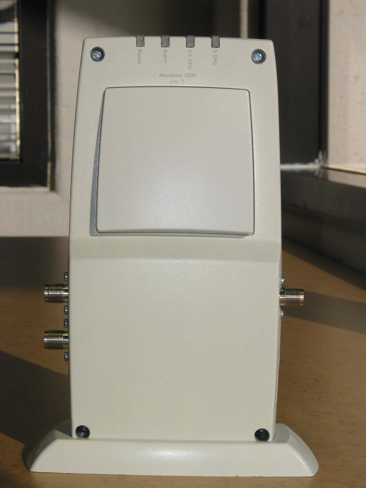
QTZWN1200BG
Dec 17, 20032.4 GHz 802.11 Access Point
Equipment Class
DTS - Digital Transmission System