QTZVAP1200802.11 Dual Band Access Point
Airespace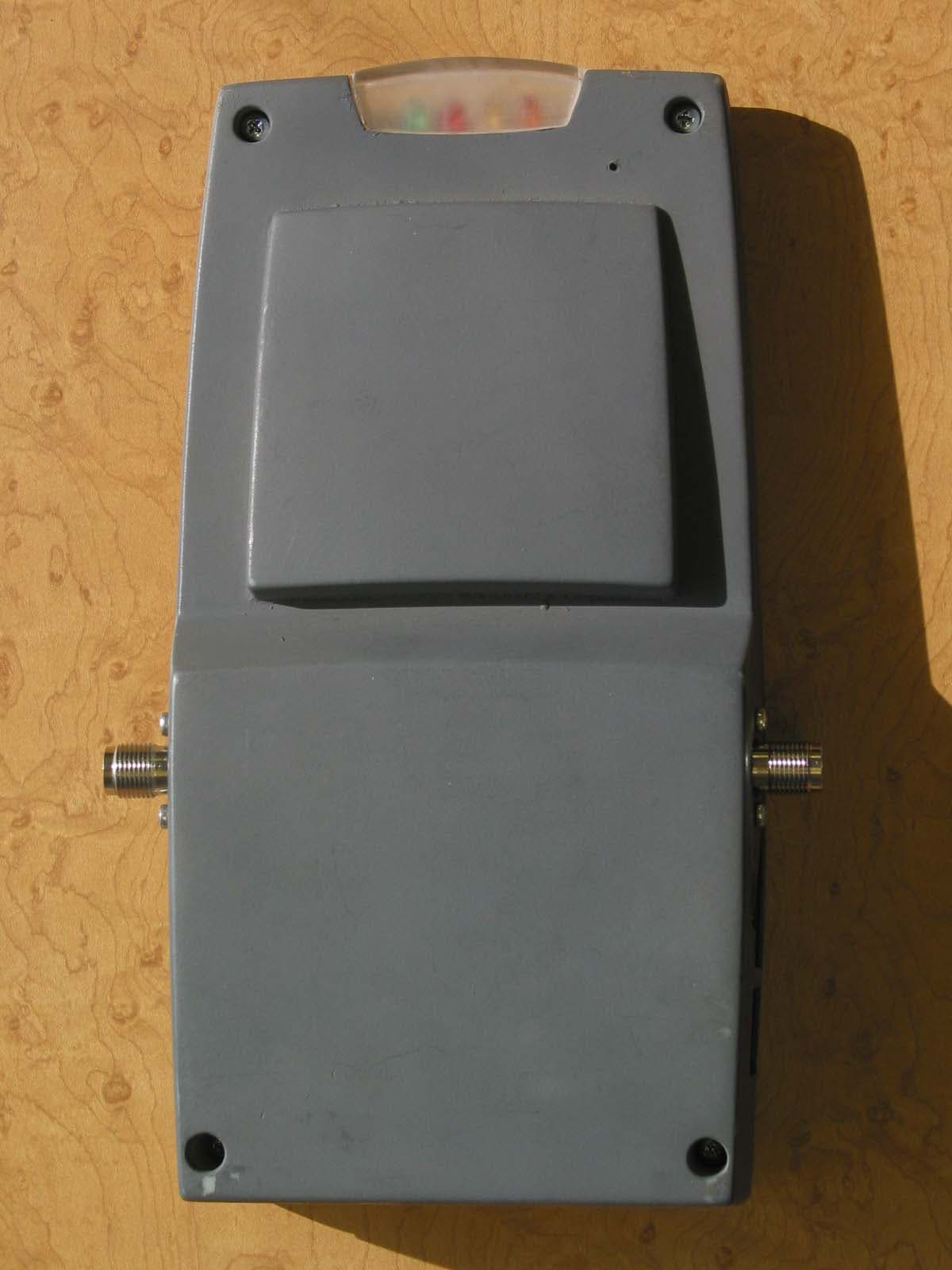
Click to zoom
Application Details
- Equipment Class
- DTS - Digital Transmission System
- Date of Grant
- Mar 09, 2003
- Application Purpose
- Original Equipment
- Date of Application
- Mar 09, 2003
- Equipment Note
- 802.11 Dual Band Access Point
- Frequency Range
- 2412.00000000 - 2462.00000000
- Company
- Airespace
- Country
- United States
Documents & Files
Document Text
Text extracted from the exhibit documents filed with the FCC. Open a document above to read the original.
Users Manual
Copyright © 2003 Airespace, Inc. All Rights Reserved. 1 Airspace Access Point (AP) Installation Guide Airespace System 1.0: March 5, 2003 Airespace, Inc. 110 Nortech Parkway San Jose, CA 95134 1-408-635-2000 www.airespace.com Copyright © 2003 Airespace, Inc. All Rights Reserved. 2 Legal Information Disclaimer The descriptions and specifications included in this document are subject to change without notice. All statements in this document were believed to be accurate when the document was created, but no warranty, expressed or implied, is given with this document. Users are required to take full responsibility for their actions in using this document and the products it describes. Notwithstanding any other warranty included in this document, the files, software, and printouts of this document are provided "AS IS" including any and all faults. Trademarks and Service Marks Airespace™, Airespace AP™ and Secure Airespace™ are trademarks of Airespace, Inc. All other trademarks, service marks, and product names used in this document are the property of their respective owners. U.S.A. Government Restricted Rights (tbd) Applicable Laws (tbd) Copyright © 2003 Airespace, Inc. All Rights Reserved. 3 FCC Statements This equipment has been tested and found to comply with the limits for a Class A digital device, pursuant to Part 15 of the FCC Rules. These limits are designed to provide reasonable protection against harmful interference when the equipment is operated in a commercial environment. This equipment generates, uses, and can radiate radio frequency energy and, if not installed and used in accordance with the instruction manual, may cause harmful interference to radio communications. Operation of this equipment in a residential area is likely to cause harmful interference in which case the user will be required to correct the interference at his own expense. RF Radiation Hazard Warning To ensure compliance with FCC RF exposure requirements, this device must be installed in a location such that the antenna of the device will be greater than 20 cm (8 in.) from all persons. Using higher gain antennas and types of antennas not covered under the FCC certification of this product is not allowed. Note: No external antennas are currently certified or available in this release. Installers of the radio and end users of the system must adhere to the installation instructions provided in this manual. Non-Modification Statement Use only the supplied internal antenna, or external antennas supplied by the manufacturer. Unauthorized antennas, modifications, or attachments could damage the badge and could violate FCC regulations and void the user’s authority to operate the equipment. Note: No external antennas are currently certified or available in this release. Deployment Statement This product is certified for indoor deployment only. Do not install or use this product outdoors. Copyright © 2003 Airspace, Inc. All Rights Reserved. 4 Table of Contents Airspace Access Point (AP) Installation Guide 1 Legal Information 2 Disclaimer 2 Trademarks and Service Marks 2 U.S.A. Government Restricted Rights 2 Applicable Laws 2 FCC Statements 3 RF Radiation Hazard Warning 3 Non-Modification Statement 3 Deployment Statement 3 Table of Contents 4 About this Guide 5 About the Airespace Access Point 6 About Airespace AP Models 9 About Internal and External Airespace AP Antennas 10 About Airespace AP LEDs 11 About Airespace AP Connectors 12 About Airespace AP Physical Security 13 About Power Over Ethernet 14 Installing Airespace APs 15 Planning Airespace AP Locations 16 Mounting Airespace APs 17 Copyright © 2003 Airespace, Inc. All Rights Reserved. 5 About this Guide The Airespace Access Point (AP) Installation Guide allows installation planners, network administrators, and installers to work together to install Airespace APs in a target environment. Refer to the following sections for more information about the Airespace AP. Copyright © 2003 Airespace, Inc. All Rights Reserved. 6 About the Airespace Access Point The Airespace AP is a part of the innovative Airespace System, which provides unmatched scalability and security solutions for enterprises and Wireless ISPs. When associated with an Airespace 4000 Switch as shown in the following figure, the Airespace AP provides advanced 802.11a and/or 802.11b Access Point functions in a single sleek enclosure. In the Airespace System, most of the processing power is removed from a traditional AP to the Airespace Switch. Airespace Switch and APs Copyright © 2003 Airspace, Inc. All Rights Reserved. 7 The following figure shows an Airespace AP with the optional ceiling mount base. Airespace AP with Ceiling Mount Base Refer to the following for more information on Airespace APs: • Airespace AP Models • Internal and External Airespace AP Antennas • About Ethernet Cabling • Airespace AP LEDs • Airespace AP Connectors • Airespace AP Power Requirements • Airespace AP External Power Converter • About Power Over Ethernet (PoE) Copyright © 2003 Airspace, Inc. All Rights Reserved. 8 • Airespace AP Physical Security • Airespace AP Automatic Software Upgrades • Airespace AP Specifications • Installing Airespace APs Copyright © 2003 Airespace, Inc. All Rights Reserved. 9 About Airespace AP Models The Airespace AP includes one 802.11a radio (1200A), one 802.11b radio (1200B), or one 802.11a and one 802.11b radio (1200AB). The Airespace AP comes in the following configurations: • Model 1200A - Airespace AP with one 802.11a radio and two high-gain internal antennas • Model 1200B - Airespace AP with one 802.11b radio and two high-gain internal antennas • Model 1200AB - Airespace AP with one 802.11a and one 802.11b radio and four high- gain internal antennas The Airespace AP is shipped with a color-coordinated ceiling mount base, and projection and flush wall mount brackets. These brackets and base allow quick mounting to ceiling or wall: • Ceiling Mounting Kit - Allows you to mount the Airespace AP o…
Text truncated - open the document above for the full version.
Cover Letter(s)
To: Federal Communications Commission 7435 Oakland Mills Road Columbia, Maryland 21046 Subject: Confidentiality Request for Certification Application Gentlemen, On behalf of Airespace I request that the following documents associated with the Part 15 Certification application for FCC ID: QTZVAP1200 be withheld from public disclosure per Section 0.459 of the FCC Rules. All circuit schematics. All electrical block diagrams All parts lists This request is made under the provisions of Section 0.457(d) of the FCC rules and Sections 552(b)(4) of the Freedom of information Act. These Sections authorize withholding from public inspection, materials which would be privileged as a matter of law if retained by the person submitting them in addition to materials, which would not customarily be released to the public, by that person. If you have any questions, please do not hesitate to contact me at: [email protected] or (408) 832-7053 Sincerely, David Waitt Consultant representing Airespace 110 Nortech Parkway San Jose, CA, 95134
Cover Letter(s)
American Telecommunications Certification Body Inc. 6731 Whittier Ave, McLean, VA 22101 February 10, 2003 RE: Airespace FCC ID: QTZVAP1200 I have a few comments on the above referenced Application. 1) The external photos appear to show 2 RF connectors (possibly TNC). However these connectors do not appear to be shown in the internal photographs or test photos (these appear to contain 2 different RF connectors-possibly SMA). None of these ports appear to have been used. Are these photographs of the same device. Please explain. 2) Please provide photographs and descriptions of each antenna used in/within the device. 3) The internal photographs must show the top and bottom of each board. However the internal photographs only appear to show the top of one main board. Additionally, close up photographs of the RF TX boards should be provided (including the top and bottom and also with the subshields installed and removed). Please provide additional photos as necessary. 4) Please label one of the photographs to show which antennas are for use with what part of the TX (i.e. 15.247 vs. UNII). 5) Please provide a exhibit for the operational description of the device. 6) The schematics/block diagram show a variety of internal/external antenna possibilities. Please provide a list of the specific antenna configurations tested and included for compliance of this device. From the test photographs, it appears only the internal antennas were tested. 7) The FCC statements in the users manual state the device is a class A device. Please provide a justification for Class A environment. 8) The users manual mentions various models of the EUT with different combinations of A/B cards. Please call to discuss. Note: The part list explains that the device has an RF card access panel. 15.247 Specific Information 9) The RF exposure mentions +17 dBm setting, however the maximum power listed is 15.29. Was the device not functioning correctly or was there additional loss measured through a switch? Please explain. Note that the device is expected to be tested under the highest TX power and match the manufactures expected power. 10) Page 4 of the test report states the antenna are “integral” to the 802.11 A/B boards. Is this correct or are they integral to the host device? 11) Please explain precautions that are in place so that the end user is not capable of setting the low or high channels to +17 dBm. For instance the drivers should not allow the +17 dBm setting on these channels. 12) The test data from Elliott labs seems to show data entitled (Atheros Reference Card) that are higher than the final measurements shown. Please explain. 13) Note: For antenna conducted spurious measurements, the FCC specifies 100 kHz. Please use this setting for future submittals. Timothy R. Johnson Examining Engineer mailto: [email protected] The items indicated above must be submitted before processing can continue on the above referenced application. Failure to provide the requested information may result in application termination. Correspondence should be considered part of the permanent submission and may be viewed from the Internet after a Grant of Equipment Authorization is issued. z Page 2February 10, 2003 Please do not respond to this correspondence using the email reply button. In order for your response to be processed expeditiously, you must submit your documents through the AmericanTCB.com website. Also, please note that partial responses increase processing time and should not be submitted. Any questions about the content of this correspondence should be directed to the sender.
Cover Letter(s)
American Telecommunications Certification Body Inc. 6731 Whittier Ave, McLean, VA 22101 February 14, 2003 RE: Airespace FCC ID: QTZVAP1200 I have a few comments on the above referenced Application. General Information 1) It does not appear that AC power line conducted emissions were supplied to show compliance with 15.207. Please provide this information. Please note that while the final device may be subjected to 15A Verification requirements, the limits of 15.207 for the TX portion of the device are equivalent to Class B. Any emissions that exceed the limits of 15.207, but meet 15.107 class A limits must be shown to not originate from the TX portion of the device. 2) Please verify that the device has been properly tested to for Part 15, Class A limits as previously mentioned. UNII Specific Information 3) The UNII Block Diagram in the UNII test report shows a splitter that goes to 2 different internal antennas as well as FET switch. The photographs do not appear to show a splitter or switch. Are these in the device. Please explain or provide labeled photographs to show these components. 4) The “Report Organization and Results Summary” paragraph incorrectly references 15.247. 5) The list of measurement antennas given in the equipment list appears incomplete. Please review. 6) Please provide an attestation from the manufacturer regarding the reduction of power (both 802.11 A/B) being programmed and set in the final product such that the end user can not adjust the power above the set points determined. 7) Please explain if this device contains a "Turbo" mode of operation. If so, was this feature tested? 8) The power measurements were made using a power meter. The FCC has published acceptable procedures using a spectrum analyzer, but do not mention using a power meter. I believe that there has been some concern regarding the accuracy of power meters for measurement of wideband signal that are greater than 10 MHz. I have provided a copy of the FCC recently published notice for your review. 9) The setpoints appear to agree with the measured power when lowered to 10 dBm, but have a variation of 3 dB on the higher set points. Please explain. 10) In the 5.15-5.25 GHz band, the channel 36 power was measured at 16.9 dBm with a setpoint of +13 dBm and a limit of +17 dBm. However channel 48 has a setpoint of +14 dBm with a limit of +17 dBm, but appears not to be measured. Please provide power measurements for this channel (reference 15.407(b)(7)). 11) Please provide information regarding 15.407(c), (d), (e), & (g). Note that the "access door" and any information to the user on how to install the unit will be a concern for operation in the 5.15-5.25 due to the integral antenna requirement. Note that an antenna that attaches with a connector inside of the case is acceptable, provided that there is no need for the user to ever open the case. 12) Is the second paragraph in the procedure regarding the 5 GHz Out of Band Spurious Emissions correct. This appears to be referencing the 15.247 conducted test using a 100 kHz RBW. The plots for this test do show the expected 1 MHz RBW setting. Additionally, please add the limits to the tabular results. 13) The peak excursion procedure shows "?" for come of the VBW settings and also appears to be provided 2 different times (Trace 1/2, Trace A/B). Additionally the information regarding the integration is only necessary for the power measurement and therefore does not apply to this procedure. Please correct. -- Continued on Next Page -- z Page 2February 14, 2003 14) The Note under the table of the 5 GHz Radiated Emissions in Restricted Bands states 15.205 and 15.209 limitations. Please note that the 15.205 references the limits of 15.209. However, this section does not appear to mention 15.407(b)(1-3). Additionally, please explain how the limit of 15.407 are taken into account in the data tables of this section. Note that the RBW appears to be met for the 5.15 and 5.35 bandedges, but it is not certain how the -17/-27 dBm/MHz requirements are shown. 15) The notes on table for Run 1b state power levels different than appear in the power level setting table earlier in the report. Please explain or correct. 16) FYI. Please note that for the Spectral Density Tests, the VBW is specified as > RBW, not > RBW. Timothy R. Johnson Examining Engineer mailto: [email protected] The items indicated above must be submitted before processing can continue on the above referenced application. Failure to provide the requested information may result in application termination. Correspondence should be considered part of the permanent submission and may be viewed from the Internet after a Grant of Equipment Authorization is issued. Please do not respond to this correspondence using the email reply button. In order for your response to be processed expeditiously, you must submit your documents through the AmericanTCB.com website. Also, please note that partial responses increase processing time and should not be submitted. Any questions about the content of this correspondence should be directed to the sender.
Cover Letter(s)
American Telecommunications Certification Body Inc. 6731 Whittier Ave, McLean, VA 22101 February 25, 2003 RE: Airespace FCC ID: QTZVAP1200 I have a few comments on the above referenced Application. General Information 1) Conducted emissions were performed only from 450 kHz to 30 MHz per 15.207 and are compared to the current FCC limits. It is recommended that the conducted emissions meet the future limits (CISPR) that will be required in the next few years (extends the frequency range and also changes the limits. This is because the grant will be issued with one of the following grant notes depending on which set of limits it is shown to have met: Current Limits NOTE: The manufacture and importation of this device must cease on July 10, 2005 pursuant to 15.37(j) or 18.123 transition provisions adopted under FCC 02-157 (ET Docket 98-80). Future Limits (CISPR) NOTE: This device has shown compliance with the conducted emissions limits in 15.107, 15.207, or 18.307 adopted under FCC 02-157 (ET Docket 98-80) and may be marketed after July 11, 2005 and is not affected by the 15.37(j) or 18.123 transition provisions Please comment on this issue. Also please note that page 5 of 46 lists the test results that may require changing if the current results will be adjusted for the CISPR limits. UNII Specific Information 2) Please provide the attestation from Airespace referenced in the reply. 3) The AC conducted paragraph listed on page 5 of 46 should be 15.207. Please correct. 4) The external antennas with the connectors already attached to the device are not suitable for the 5.15-5.25 GHz band (according to information in the application these will be added at a later date via a permissive change). Please explain. 5) Your response mentions that different models in the future may allow the user to upgrade the units. Please note that for the 5.15 to 5.25 GHz band, the antenna connections currently provided in the product are not acceptable for the FCC’s intent of the integral antenna requirement if the user is expected to remove the “access door”. Note that an antenna that attaches with a connector inside of the case is acceptable, provided that there is no need for the user to ever open the case. Therefore the users manual should not make any reference or explanation to the user on how to open the device. Additionally, the cover should be sealed such that the user has no easy way to open. For instance the use of special screws so that the user can not simply open the device with any standard household screwdriver set, or the door may be “glued” shut. 6) The test procedures issued by the FCC do describe the intent to obtain “average power” (see attached document). From our discussion Airespace has also made many measurements (both peak and average) to the transmitter to help explain some differences previously discussed. Please add a column for average measurements or adjust the power measurements for average measurements (note this may also affect the RF exposure calculations provided and any summary of results shown). 7) Please provide an updated users manual which includes the statements necessary for 15.407(e) as referenced in your last reply. 8) Your response regarding 15.407(g) mentions that the transmit frequency did not drift out of band. Please confirm that this includes all of the occupied bandwidth within 26 dB of the fundamental. z Page 2March 7, 2003 9) Please verify the data on page 27 of 46. It appears that 2 points may be out of specification or the incorrect limits applied. However this data also appears to be presented with correct limits on page 34 of 46. Please explain. 10) Note that spurious emissions NOT falling in restricted bands must also meet the requirement of 27dBm/MHz. This device appears to meet this although information in the report was not given. Note that 27 dBm/MHz may be calculated using the far field equations and equals a limit of – 38.8 dBm / 68.3 dBuV/m @ 3 meters. Please comment. Timothy R. Johnson Examining Engineer mailto: [email protected] The items indicated above must be submitted before processing can continue on the above referenced application. Failure to provide the requested information may result in application termination. Correspondence should be considered part of the permanent submission and may be viewed from the Internet after a Grant of Equipment Authorization is issued. Please do not respond to this correspondence using the email reply button. In order for your response to be processed expeditiously, you must submit your documents through the AmericanTCB.com website. Also, please note that partial responses increase processing time and should not be submitted. Any questions about the content of this correspondence should be directed to the sender.
Cover Letter(s)
To: Mr. Tim Johnson, American TCB From: David Waitt, (Representing) Airespace Subject: Inquiries regarding Certification application for FCC ID QTZVAP1200 Date: 10 Feb 2003 Tim, Below are the replies to your inquiries regarding this application. The answers are numbered corresponding to your inquiries in your latter dated 10 Feb 2003. If something is unclear, or if you have additional concerns, please contact me. Best Regards, David Waitt Consultant representing Airespace 1: There are two reverse TNC connectors on the productions versions Airespace VAP1200 radio. The housing of the unit that was tested for FCC compliance was a prototype unit. The design of the housing was not complete at the time of compliance testing, nor was connector selection complete. The prototype housing incorporated SMA connectors, while the production version will incorporate R-TNC connectors. This is the reason for the photos of two different units. The prototype housing was tested while the production version was photographed. However, the external connectors will not be used in this particular radio at this time. The firmware within the radio will prevent the selection of an external antenna. It is anticipated in the future that use of external antennas will be authorized with a permissive change to this grant. External antennas were not tested for this application because external antenna selection has not been finalized. To reduce the cost of modifying the tooling of the product once the external antenna selection is finalized, and the permissive change granted, the external connectors were incorporated into the unit early in the product development cycle. 2: Detailed pictures of the 2.4 and 5 GHz antennas are included in the document VAP1200_int_photos.pdf that has been uploaded. 3: Additional detailed photos of the main PCB in the radio as well as the RF module are included in the document VAP1200_int_photos.pdf that has been uploaded. 4: Additional detailed photos of the antennas within the radio are included in the document VAP1200_int_photos.pdf that has been uploaded. The 2.4 GHz and the 5GHz antennas have been identified in the photos. 5: Operational description 6: The only antennas that will be used with this product are the internal antennas that were tested for compliance. Use of external antennas currently will be disabled. External antennas may be authorized in the future with a permissive change 7: The Airespace VAP1200 (and its associated Ethernet switch) is intended only for industrial / corporate environments. Marketing of the products will not be targeted at individuals for residential use. The VAP1200 will not be available for purchase at consumer oriented retail outlets. 8: This product (FCC ID QTZVAP1200) is an 802.11-A/B radio. The same housing and PCB will be used in future Airespace products that will be certified as either an 802.11-A OR an 802.11-B radio (not a combo radio). Thus, a future single band radio will still have two RF module slots, only one of which will be used. The reason for this is to allow the use of one housing and one PCB to be factory configured for three different products (802.11 A/B, 802.11 A, 802.11 B). The user access panel will be used in the future to allow users to upgrade a single band radio to a dual band radio. Airespace realizes there are some FCC compliance issues associated with this “upgrade-ability” that will be addressed in the certification of the future single band radio certification applications. For the current certification, since both RF module slots will be occupied, no upgrade is possible. 15.247 Specific Inquiries 9: 17 dBm setting = 15.29 dBm 10: In this case, on page four, the references the fact that the VAP has integral antennas for each band. The antennas are integral to the VAP. The antennas are NOT part of the RF modules contained in the VAP. 11: The firmware within the VAP will ONLY allow FCC compliant configurations. The firmware will prevent the output power from being set to an inappropriate level on a specific channel. 12: The reference to the “Atheros Reference Card” in the data within the appendix is troubleshooting data. During the compliance testing, for comparison purposes, a “Reference card” was borrowed from Atheros Corp to compare the test results of that reference card to the test results of the production module that was being tested in the Airespace VAP radio. 13: Whoops! Noted.
Cover Letter(s)
To: Mr. Tim Johnson, American TCB From: David Waitt, Airespace Subject: Inquiries regarding Certification application for FCC ID QTZVAP1200 Date: 23 Feb 2003 Tim, Below are the replies to your inquiries regarding this application. The answers are numbered corresponding to your inquiries in your latter dated 10 Feb 2003. If something is unclear, or if you have additional concerns, please contact me. Best Regards, David Waitt Consultant representing Airespace ATCB #1: The external photos appear to show 2 RF connectors (possibly TNC). However these connectors do not appear to be shown in the internal photographs or test photos (these appear to contain 2 different RF connectors-possibly SMA). None of these ports appear to have been used. Are these photographs of the same device. Please explain. Airespace: There are two reverse TNC connectors on the productions versions Airespace VAP1200 radio. The housing of the unit that was tested for FCC compliance was a prototype unit. The design of the housing was not complete at the time of compliance testing, nor was connector selection complete. The prototype housing incorporated SMA connectors, while the production version will incorporate R-TNC connectors. This is the reason for the photos of two different units. The prototype housing was tested while the production version was photographed. However, the external connectors will not be used in this particular radio at this time. The firmware within the radio will prevent the selection of an external antenna. It is anticipated in the future that use of external antennas will be authorized with a permissive change to this grant. External antennas were not tested for this application because external antenna selection has not been finalized. To reduce the cost of modifying the tooling of the product once the external antenna selection is finalized, and the permissive change granted, the external connectors were incorporated into the unit early in the product development cycle. ATCB #2: Please provide photographs and descriptions of each antenna used in/within the device. Airespace: Detailed pictures of the 2.4 and 5 GHz antennas are included in the document VAP1200_int_photos.pdf that has been uploaded. ATCB #3: The internal photographs must show the top and bottom of each board. However the internal photographs only appear to show the top of one main board. Additionally, close up photographs of the RF TX boards should be provided (including the top and bottom and also with the subshields installed and removed). Please provide additional photos as necessary. Airespace: Additional detailed photos of the main PCB in the radio as well as the RF module are included in the document VAP1200_int_photos.pdf that has been uploaded. ATCB #4: Please label one of the photographs to show which antennas are for use with what part of the TX (i.e. 15.247 vs. UNII). Airespace: Additional detailed photos of the antennas within the radio are included in the document VAP1200_int_photos.pdf that has been uploaded. The 2.4 GHz and the 5GHz antennas have been identified in the photos ATCB #5: Please provide a exhibit for the operational description of the device. Airespace: A brief operational description of the device is contained on page 4 of the test report ATCB #6: The schematics/block diagram shows a variety of internal/external antenna possibilities. Please provide a list of the specific antenna configurations tested and included for compliance of this device. From the test photographs, it appears only the internal antennas were tested. Airespace: Antennas that will be used with this product are the internal antennas that were tested for compliance. Use of external antennas currently will be disabled. External antennas may be authorized in the future with a permissive change. ATCB #7: The FCC statements in the users manual state the device is a class A device. Please provide a justification for Class A environment. Airespace: The Airespace VAP1200 (and its associated Ethernet switch) is intended only for industrial / corporate environments. Marketing of the products will not be targeted at individuals for residential use. The VAP1200 will not be available for purchase at consumer oriented retail outlets. 15.247 Specific Information ATCB #8: The users manual mentions various models of the EUT with different combinations of A/B cards. Please call to discuss. Note: The part list explains that the device has an RF card access panel. Airespace: This product (FCC ID QTZVAP1200) is an 802.11-A/B radio. The same housing and PCB will be used in future Airespace products that will be certified as either an 802.11-A OR an 802.11-B radio (not a combo radio). Thus, a future single band radio will still have two RF module slots, only one of which will be used. The reason for this is to allow the use of one housing and one PCB to be factory configured for three different products (802.11 A/B, 802.11 A, 802.11 B) Additionally: • The 802.11 A/B VAP radio uses the same 802.11 …
Text truncated - open the document above for the full version.
Contact Information
Applicant
Bob Friday(Sr. Scientist)
Technical Contact
Non-Technical Contact
ConsultantDavid Waitt
[email protected]408-832-7053
Test Firm
Elliott Laboratories LLCDavid Bare
Technical Specifications
| # | Rule Parts | Frequency Range | Power Output |
|---|---|---|---|
| 1 | 15C | 2.41 GHz - 2.46 GHz | 34.00 mW |
Other Applications from Airespace
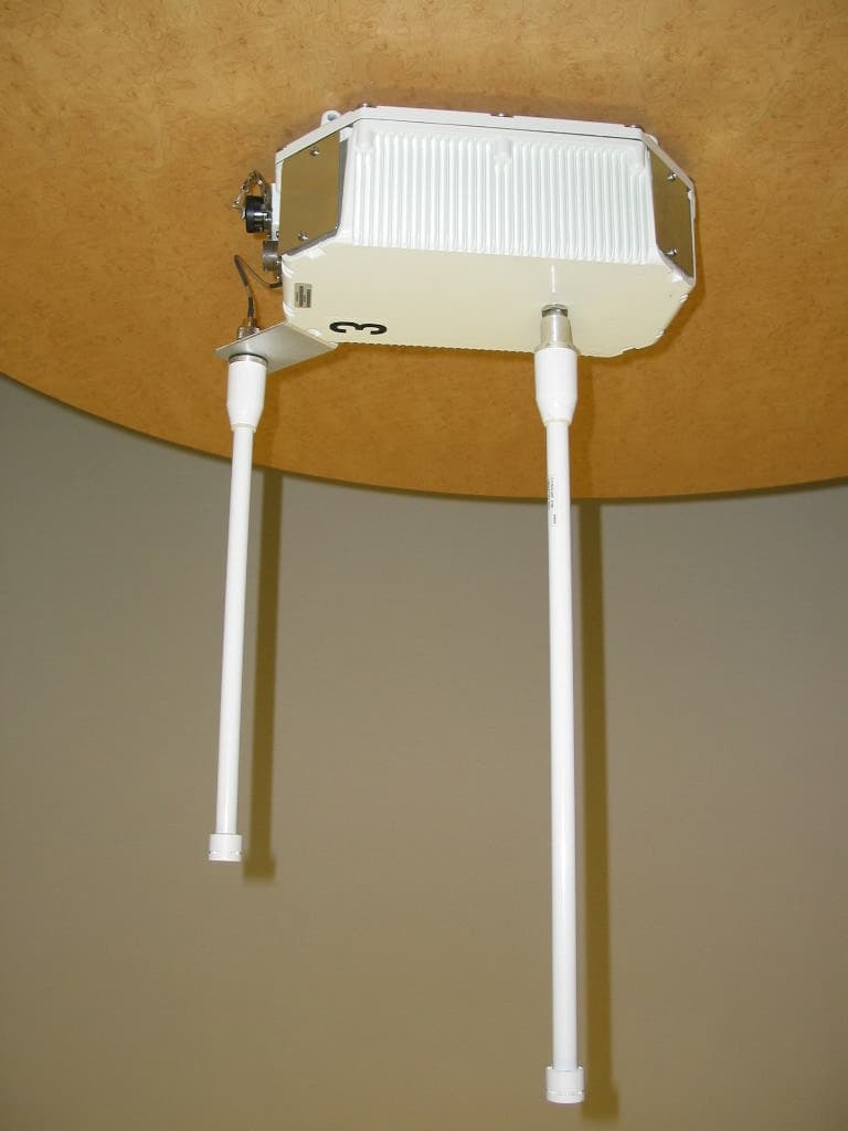
QTZ1300
Mar 30, 2005Outdoor Access Point
Equipment Class
DTS - Digital Transmission System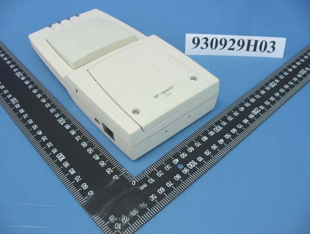
QTZ1200D
Dec 16, 2004IEEE 802.11 a/g Wireless LAN Access Point
Equipment Class
NII - Unlicensed National Information Infrastructure TXQTZ1200W
Jun 19, 2004802.11 Dual Band Access Point
Equipment Class
DTS - Digital Transmission System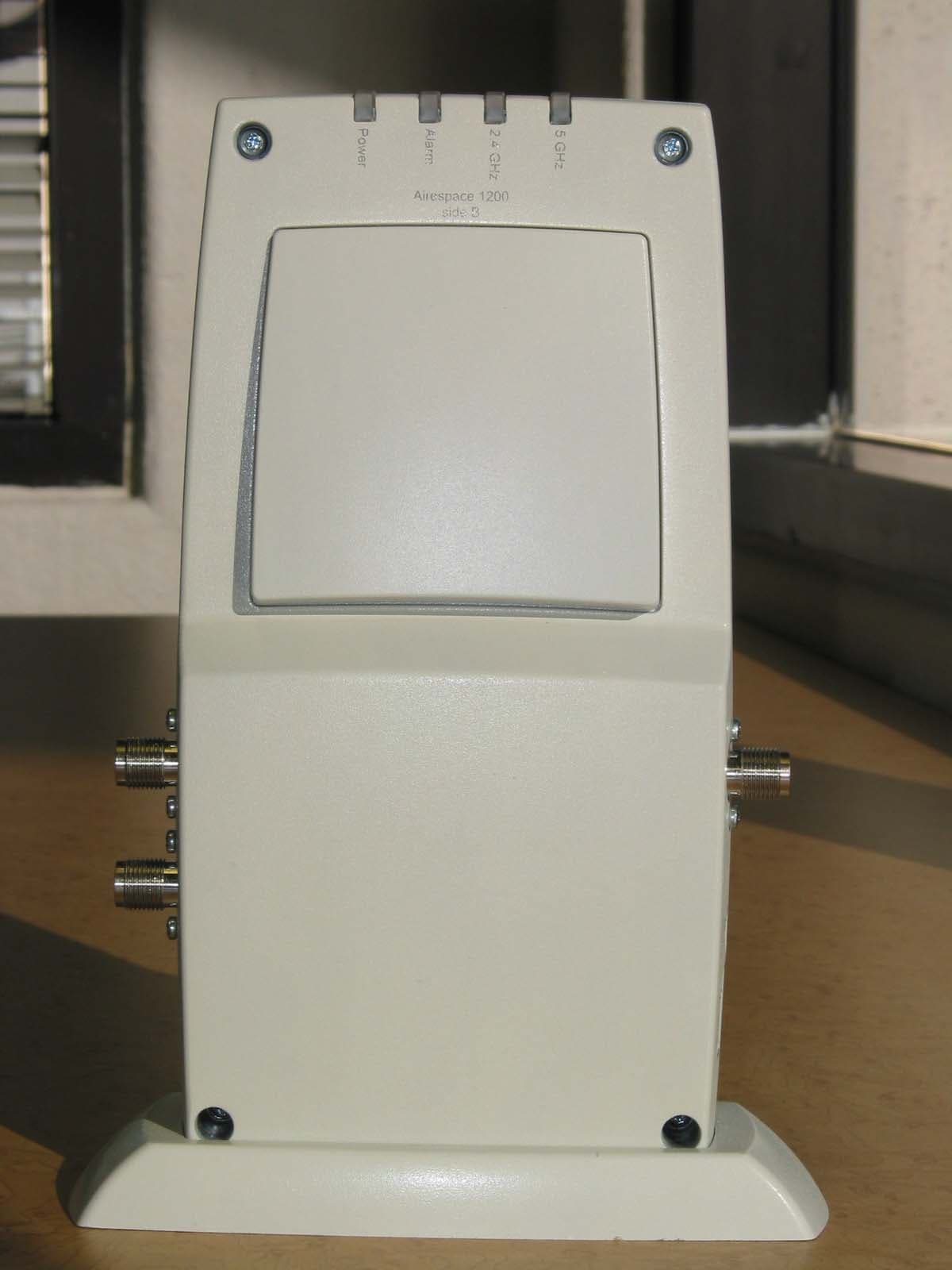
QTZAM1200ABG
Jan 12, 2004802.11 Dual Band Access Point
Equipment Class
DTS - Digital Transmission System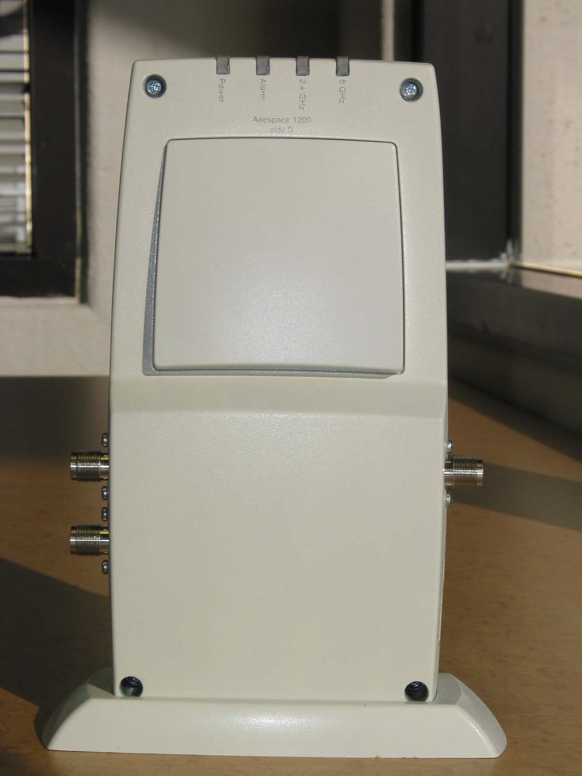
QTZWN1200BG
Dec 17, 20032.4 GHz 802.11 Access Point
Equipment Class
DTS - Digital Transmission System