QUUI28CTRemote Control
Superwinch, LLC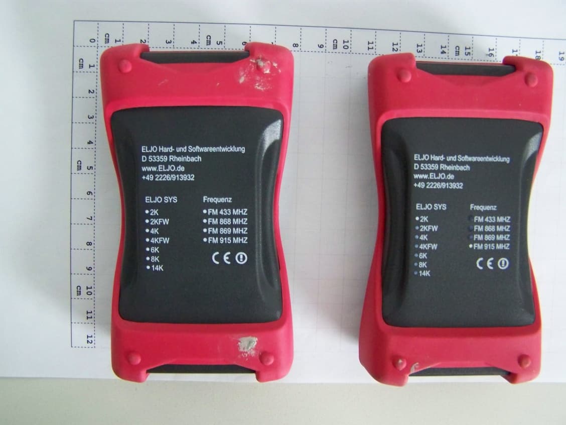
Click to zoom
Application Details
- Equipment Class
- DXX - Part 15 Low Power Communication Device Transmitter
- Date of Grant
- Aug 16, 2011
- Application Purpose
- Original Equipment
- Date of Application
- Aug 16, 2011
- Equipment Note
- Remote Control
- Frequency Range
- 914.50000000 - 914.50000000
- Company
- Superwinch, LLC
- Country
- United States
Documents & Files
Document Text
Text extracted from the exhibit documents filed with the FCC. Open a document above to read the original.
Users Manual
CERTUS WIRELESS REMOTE SYSTEM – INDUSTRIAL VERSION Please read the manual thoroughly before installing or using the radio remote control. e customer must fully understand this manual. If there are questions or concerns, please contact the company delivering the unit or the manufacturer. e radio remote unit is only allowed for use in products whose use oers no danger for person or property if there is an interruption in transmission or receiving of the signal. Additionally, there should be a manual emergency stop which is able to shut down the entire unit of machinery apart from the radio remote stop. It is not allowed to use a radio remote control with machinery which could be subject to heightened accident risk. e manufacturer cannot judge whether the proper procedure has been followed with the installation of the remote unit. Improper installation or improper use of the remote unit by the user could result in injury or destruction of property. For that reason, the manufacturer cannot be responsible for personal injury, property damage or loss of any time resulting from either improper installation, improper use or wrong use of the product. Likewise, the manufacturer assumes no liability for damages resulting from improper maintenance. e manual should be kept within easy reach and should be given to the next owner in case of a sale. General Information e system operates on a frequency of FM 869.85 MHZ (EU) or FM 914.5 (US) and utilizes frequency modulation generally known as FM technology. While an FM signal is much less susceptible to electrical interference than an AM signal, there can never be total protection against outside interference. Interference can result from the turning on and o of electronic equipment and stronger interference can come from proximity to relay stations, industrial equipment and types of computer equipment. Another interference factor could be the close proximity of strong electric motors. e above factors should be considered when installing the wireless system. Also, the greatest range will be achieved if the receiver is not enclosed in metal. TABLE OF CONTENTS 1. Safety 1.1 Safety with this wireless unit 1.2 Safety warnings and tips 1.3 Potential areas of danger 1.4 Approved operators 1.5 Safety factors in the work area 1.6 Safety Components 1.7 Emergency Procedures 2. Instructions for Use 2.1 Transmitter2.2 Receiver 2.1.1 Front and Back View 2.1.2 Technical Information 2.1.3 Setting Transmitter code 2.1.4 Optical Signals transmitter 2.1.5 Changing the Battery 2.1.6 Internal Antenna 2.1.7 Operation of the Transmitter 2.2.1 View and Parts 2.2.2 Technical Information 2.2.3 Setting Receiver code 2.2.4 Optical Signals Receiver 2.2.5 Internal Antennae 2.2.6 Operation of the Receiver 2.2.7 Allocation of Terminals 3. Tips for Connector allocation and start up 4. Using the Wireless System 4.1 Optical check 4.2 Safety Check and starting the system 5. Care and Maintenance 6. Troubleshooting Guide 7. Mounting the unit and running the safety test: 1.1 Safety of this radio remote control is wireless system is equipped with electronic safety devices THE FOLLOWING IS IMPORTANT FOR YOUR SAFETY Misuse or abuse of this equipment could result in injury to the user or others and/or damage to property. Everyone who uses this equipment must: – Be quali!ed to use the machinery and have been introduced to the wireless system – Follow exactly the safety rules – Have read the manual with care Safety Factors 1) e product may only be installed, maintained and used by trained professionals. Repairs must be done by Superwinch. 2) Never leave the transmitter unattended. 3) e transmitter is only to be used within the con!ners of the working space and this space is to be clearly de!ned. 4) Using more than one transmitter for one receiver box is not allowed. If you own or purchase a backup transmitter it is important to note: improperly stowing a second transmitter is a security risk. When the system is !rst put into use, the backup unit should be tested then have it’s battery removed and the unit should be stored in a secure place. If these safety regulations are not followed closely, the machine could be set in motion by a non-professional by accident and this could result in serious injury or death. 5) Both the transmitter housing and buttons should be checked on a daily basis and, if damage is present, the transmitter should be taken out of use. 6) Also, the battery level must be checked daily. If the battery level is too low and LED light 2 on the transmitter is "ashing, then the battery should be changed. 7) e stop button should be checked before each shi# to see if the signal is reaching the receiver. 8) In an emergency situation, pressing the red emergency stop button should immediately activate the stop relay in the receiver and the electrical current to the machine should be cut. 1.6 Safety Features e machine will be brought to a stop if: – the red stop button is activated – the operating range is exceeded – system encounters the same frequency from an outside source – !ve minutes go by since the last transmission ese safety features are engineered into the system to protect personnel and equipment and should never be changed, taken out or bypassed. 1.7 Emergency Procedure If an emergency situation arises immediately press the emergency stop button (red) on the transmitter. en follow the procedures as outlined in the manual for the machinery being used. 2. Instructions for Use Before using the wireless unit, make sure to have read and fully understood this manual, especially Chapter 1 on safety and safety features. 2.1 Transmitter 2.1.1 Front and Back views and operational controls Illustration 1 : Illustration 2 : Front of Transmitter Back of Transmitter LED 1 Stop Button STOP LED 1 LED 2 Stop Button Button 1 Button 2 STOP 2.1.2 Technical Data – Transmitter Frequency FM 914.5 MHZ Number of Functions 2 plus emergency stop Antennae internal (wire antennae 50mm) LED …
Text truncated - open the document above for the full version.
External Photos
Annex 2 to Test Report TR2-0003-11-1-1b_A2, Page 3 of 5 TR2-0003-11-1-1b_A3 1. Photos of measurement set-up Photograph 1: Front view of the EUT A(right) and EUT C (left), scaling in cm. Photograph 2: Rear side of the EUT A(right) and EUT C (left)
Internal Photos
Annex 2 to Test Report TR2-0003-11-1-1b_A2, Page 4 of 5 TR2-0003-11-1-1b_A3 Photograph 3: EUT B used for conducted tests Photograph 4: PCB layout front side (antenna integrated) Annex 2 to Test Report TR2-0003-11-1-1b_A2, Page 5 of 5 TR2-0003-11-1-1b_A3 Photograph 5: PCB layout removed rear side of EUT A with cover(right) Photograph 6: PCB layout removed rear side of EUT C with cover(right)
Test Report
Page 1 of 27 The test results relate only to the individual items which have been tested. This report shall not be reproduced in parts without the written approval of the testing laboratory © Copyright: All rights reserved by CETECOM Laboratory Accreditation and Listings Reg. No.: 736496 MRA US-EU 0003 Industry Canada Reg. No.: 3462D-1 Reg. No.: 3462D-2 Voluntary Controls for Electromagnetic Emissions Reg. No.: R-2665, R-2666 C-2914, T-1967, G-301 accredited according to DIN EN ISO/IEC 17025 CETECOM GmbH Laboratory Radio Communications & Electromagnetic Compatibility Im Teelbruch 116 • 45219 Essen • Germany Registered in Essen, Germany, Reg. No.: HRB Essen 8984 Tel.: + 49 (0) 20 54 / 95 19-954 • Fax: + 49 (0) 20 54 / 95 19-964 E-mail: [email protected] • Internet: www.cetecom.com T E S T R E P O R T No.: TR2-0003-11-1-1b for CERTUS Wireless System I28CT – Model I2CT + CERTUS Wireless System I28CT – Model I8CT FCC-ID: QUUI28CT IC: 5101A-CERTI28CT According to: FCC Regulations Part 15.249(a)(c)(d)(e) IC Regulations RSS-Gen. Issue 3 RSS-210: Issue 8 Superwinch LLC Test Report TR2-0003-11-1-1b, Page 2 of 27 TR2-0003-11-1-1b.docx Table of contents 1. SUMMARY OF TEST RESULTS...................................................................................................................... 3 1.1. TESTS OVERVIEW USA FCC and Canada IC Standards ............................................................................. 3 2. ADMINISTRATIVE DATA ............................................................................................................................... 4 2.1. Identification of the testing laboratory ............................................................................................................. 4 2.2. Test location .................................................................................................................................................... 4 2.3. Organizational items ........................................................................................................................................ 4 2.4. Applicant‟s details ........................................................................................................................................... 4 2.5. Manufacturer‟s details ..................................................................................................................................... 4 3. EQUIPMENT UNDER TEST (EUT) ................................................................................................................. 5 3.1. Additional declaration and description of main EUT ...................................................................................... 5 3.2. EUT: Type, S/N etc. and short descriptions used in this test report ................................................................ 6 3.3. Auxiliary Equipment (AE): Type, S/N etc. and short descriptions .................................................................. 6 3.4. EUT set-ups ..................................................................................................................................................... 6 3.5. EUT operating modes ...................................................................................................................................... 7 4. DESCRIPTION OF TEST SET-UP’S ................................................................................................................ 8 4.1. Test Set-up for conducted measurements ........................................................................................................ 8 4.2. Test set-up for radiated measurements ............................................................................................................ 9 5. MEASUREMENTS ............................................................................................................................................. 11 5.1. Radiated field strength emissions below 30 MHz ........................................................................................... 11 5.2. Radiated field strength emissions, 30 MHz - 1 GHz ....................................................................................... 13 5.3. Radiated emissions, above 1GHz .................................................................................................................... 17 5.4. 6-dB Bandwidth FCC 15.247,RSS-Gen ....................................................................................................... 20 5.5. Measurement uncertainties .............................................................................................................................. 22 6. INSTRUMENTS AND ANCILLARY ................................................................................................................ 23 6.1. Used equipment “CTC” ................................................................................................................................... 23 7. CORRECTION FACTORS DUE TO REDUCED MEAS. DISTANCE (F< 30 MHZ) ................................. 27 Table of annex Total pages DOCUMENT TR2-0003-11-1-1a_A1: MEASUREMENT DIAGRAMS 23 DOCUMENT TR2-0003-11-1-1a_A2: PHOTOS OF MEASUREMENT SET-UP 4 DOCUMENT TR2-0003-11-1-1a_A3: PHOTOS OF EUT 6 DOCUMENT TR2-0003-11-1-1a_A4: DECLARATION OF IDENTICAL 1 Test Report TR2-0003-11-1-1b, Page 4 of 27 TR2-0003-11-1-1b.docx 2. Administrative Data 2.1. Identification of the testing laboratory Company name: CETECOM GmbH Address: Im Teelbruch 116 45219 Essen - Kettwig Germany Responsible for testing laboratory: Dipl.-Ing. W. Richter Deputy: Dipl.-Ing. J. Schmitt Laboratory accreditations/Listings: DAkkS-Registration No. D-PL-12047-01-01 FCC-Registration No.: 736496, MRA US-EU 0003 IC-Registration No. 3462D-1, 3462D-2 VCCI Reg. No. R-2665, R-2666, C-2914, T-1967, G-301 2.2. Test location 2.2.1. Test laboratory “CTC” Company name: see chapter 2.1. Identification of the testing laboratory 2.3. Organizational items Or…
Text truncated - open the document above for the full version.
Test Report
Page 1 of 22 The test results relate only to the individual items which have been tested. This report shall not be reproduced in parts without the written approval of the testing laboratory © Copyright: All rights reserved by CETECOM Annex 1: Measurement diagrams to TEST REPORT No.: 2-0003-11-1-1b for CERTUS WIRELESS SYSTEM I28CT- Model I2CT + CERTUS WIRELESS SYSTEMI28CT – Model I8CT FCC-ID: QUUI28CT IC: 5101A-CERTI28CT Laboratory Accreditation and Listings Reg. No.: 736496 MRA US-EU 0003 Industry Canada Reg. No.: 3462D-1 Reg. No.: 3462D-2 Voluntary Controls for Electromagnetic Emissions Reg. No.: R-2665, R-2666 C-2914, T-1967, G-301 accredited according to DIN EN ISO/IEC 17025 CETECOM GmbH Laboratory Radio Communications & Electromagnetic Compatibility Im Teelbruch 116 • 45219 Essen • Germany Registered in Essen, Germany, Reg. No.: HRB Essen 8984 Tel.: + 49 (0) 20 54 / 95 19-954 • Fax: + 49 (0) 20 54 / 95 19-964 E-mail: [email protected] • Internet: www.cetecom.com According to: FCC Regulations Part 15.249 (a)(c)(d)(e) IC Regulations RSS-Gen, Issue 3 RSS-210: Issue 8 Superwinch LLC Annex 1 to Test Report 2-20003-11-1-1b, Page 2 of 22 TR2-0003-11-1-1b_A1.docx Table of contents 1. MEASUREMENT DIAGRAMS ......................................................................................................................... 3 1.1. 6 dB bandwitdh ................................................................................................................................................ 3 1.2 99% Occupied bandwidth ................................................................................................................................. 4 1.3 Radiated field strength (15.249, class B, RSS-Gen Issue 3 and RSS-210 Issue 8) ........................................... 5 1.3.1 Radiated magnetic field strength measurements (f<30MHz) 5 1.3.2 Radiated field strength (30MHz < f < 1GHz) 9 1.3.3 Radiated field strength (1GHz < f < 10GHz) 17 Annex 1 to Test Report 2-20003-11-1-1b, Page 3 of 22 TR2-0003-11-1-1b_A1.docx 1. Measurement diagrams 1.1. 6 dB bandwitdh EUT type: I2CT A Ref 10 dBmAtt 35 dB 50 kHz/Center914.5 MHzSpan500 kHz * * RBW 50 kHz VBW 1 MHz SWT 45 ms 1 PK MAXH * PRN -90 -80 -70 -60 -50 -40 -30 -20 -10 0 10 1 Marker 1 [T1 ] -10.17 dBm 914.428685897 MHz 2 Delta 2 [T1 ] 0.18 dB 135.416666667 kHz 3 Marker 3 [T1 ] -4.08 dBm 914.524839744 MHz D1 -10.1 dBm Date: 19.JUL.2011 13:28:05 Annex 1 to Test Report 2-20003-11-1-1b, Page 4 of 22 TR2-0003-11-1-1b_A1.docx 1.2 99% Occupied bandwidth EUT type: I8CT EUT type: I2CT A Ref 5 dBmAtt 10 dB* Center914.5 MHzSpan300 kHz30 kHz/ * * RBW 300 Hz VBW 3 kHz SWT 3.4 s *1 RM MAXH * -90 -80 -70 -60 -50 -40 -30 -20 -10 0 1 Marker 1 [T1 ] -8.17 dBm 914.528044872 MHz OBW 72.596153846 kHz T1 Temp 1 [T1 OBW] -31.36 dBm 914.462500000 MHz T2 Temp 2 [T1 OBW] -38.29 dBm 914.535096154 MHz Date: 11.MAY.2011 15:30:33 Ref 5 dBm A Att 10 dB Center914.5 MHzSpan300 kHz30 kHz/ *RBW 300 Hz VBW 3 kHz SWT 3.4 s *1 RM VIEW -70 -60 -50 -40 -30 -20 -10 0 1 Marker 1 [T1 ] -6.27 dBm 914.527243590 MHz OBW 71.634615385 kHz T1 Temp 1 [T1 OBW] -32.31 dBm 914.462019231 MHz T2 Temp 2 [T1 OBW] -37.92 dBm 914.533653846 MHz Date: 11.MAY.2011 14:34:25 Annex 1 to Test Report 2-20003-11-1-1b, Page 5 of 22 TR2-0003-11-1-1b_A1.docx 1.3 Radiated field strength (15.249, class B, RSS-Gen Issue 3 and RSS-210 Issue 8) 1.3.1 Radiated magnetic field strength measurements (f<30MHz) Diagram No.3.02 Common Information Test description: Magnetic Fieldstrength Measurement related to 3 m distance Test site and distance: Semi Anechoic Room with absorbers on the floor (SAR) and 3 m measurement distance Measured sides of EUT: front, right, rear, left Rec. antenna (pre-scan): height 1.00 m, parallel and 90° to EUT polarisation Turntable step: measurements in 35° steps Used filter: bypass Test specification.: FCC 15.205 § 15.209; RSS-Gen: Issue 3 Operator: TAS Operating conditions: TX-on Power during tests: full loaded batteries Comment 1: below 30M EUT: K8 EUT Information EUT Name: KIT4 [certus wireless system] Manufacturer: ELJO Serial Number: Hardware Rev: Stream line 8KV11 Software Rev: HE8ELJOALA Comment: Radio remote control (Transmitter) - 10 0 - 90 - 80 - 70 - 60 - 50 - 40 - 30 - 20 - 10 0 10 20 30 40 50 9k2030501 00 k2 003 005 001M2M3M5M1 0M203 0M Level in dBμ V/m Frequency in Hz FCC15.209_magn hor+vert FCC15.209_Magnetic_Field 19,020000 MHz 14,857 dBμV/m Annex 1 to Test Report 2-20003-11-1-1b, Page 6 of 22 TR2-0003-11-1-1b_A1.docx EMI Auto Test Template: FCC15.209_magn hor+vert Hardware Setup: HW25_FCC15109_ESCS_MgFeld_ohne_SAR_MATRIX Measurement Type: Open-Area-Test-Site Frequency Range: 9 kHz - 30 MHz Graphics Level Range: -100 dBμV/m - 50 dBμV/m Preview Measurements: Antenna height: 1000 - 1000 cm , Step Size = 0 cm , Positioning Speed = 1 Polarization: H + V Turntable position: 35 - 305 deg , Step Size = 90 deg , Positioning Speed = 8 Scan Test Template: 01_FCC_MG_FELD_PK_FAST_H&V_EUT Subrange Step Size Detectors IF BW Meas. Time Preamp 9 kHz - 150 kHz 100 Hz PK+ 200 Hz 0,01 s 0 dB 150 kHz - 30 MHz 5 kHz PK+ 10 kHz 0,01 s 0 dB Receiver: [ESS] Data Reduction: Limit Line #1: FCC15.209_Magnetic_Field Peak Search: 20 dB , Maximum Results: 10 Subrange Maxima: 10 Subranges , Maxima per Subrange: 1 Acceptance Offset: -10 dB Maximum Number of Results: 10 After Data Reduction: Interactive data reduction Adjustment: Antenna height: Adjustment with full Range , Measuring Speed = 1 Turntable position: Adjustment with full Range , Measuring Speed = 3 Template for Single Meas.: 01_FCC_MG_FELD_PK_FAST_H&V_EUT Subrange Step Size Detectors IF BW Meas. Time Preamp 9 kHz - 150 kHz 100 Hz PK+ 200 Hz 0,01 s 0 dB 150 kHz - 30 MHz 5 kHz PK+ 10 kHz 0,01 s 0 dB Receiver: [ESS] Final Measurements: Template for Single Meas.: 02_FCC_MG_FELD_QP_final_H&V_EUT Subrange Step Size Detectors IF BW Meas. Time Preamp 9 kHz - 150 kHz 100 Hz QPK 200 Hz 1 s 0 dB 150 kHz - 30 MHz 5 kHz QPK 10 kHz 1 s 0 dB Receiver: [ESS] Report Settings:…
Text truncated - open the document above for the full version.
Test Setup Photos
Page 1 of 4 The test results relate only to the individual items which have been tested. This report shall not be reproduced in parts without the written approval of the testing laboratory © Copyright: All rights reserved by CETECOM Annex 2: Photos of measurement set-up to TEST REPORT No.: TR2-0003-11-1-1b for CERTUS WIRELESS SYSTEM I28CT – Model I2CT + CERTUS WIRELESS SYSTEM I28CT – Model I8CT FCC-ID: QUUI28CT IC: 5101A-CERTI28CT Laboratory Accreditation and Listings Reg. No.: 736496 MRA US-EU 0003 Industry Canada Reg. No.: 3462D-1 Reg. No.: 3462D-2 Voluntary Controls for Electromagnetic Emissions Reg. No.: R-2665, R-2666 C-2914, T-1967, G-301 accredited according to DIN EN ISO/IEC 17025 CETECOM GmbH Laboratory Radio Communications & Electromagnetic Compatibility Im Teelbruch 116 • 45219 Essen • Germany Registered in Essen, Germany, Reg. No.: HRB Essen 8984 Tel.: + 49 (0) 20 54 / 95 19-954 • Fax: + 49 (0) 20 54 / 95 19-964 E-mail: [email protected] • Internet: www.cetecom.com According to: FCC Regulations Part 15.249 (a)(c)(d)(e) IC Regulations RSS-Gen Issue 3 RSS-210: Issue 8 Superwinch LLC Annex 2 to Test Report TR2-0003-11-1-1b_A2, Page 2 of 4 TR2-0003-11-1-1b_A2.docx Table of contents 1. PHOTOS OF MEASUREMENT SET-UP ......................................................................................................... 3 Annex 2 to Test Report TR2-0003-11-1-1b_A2, Page 3 of 4 TR2-0003-11-1-1b_A2.docx 1. Photos of measurement set-up Photograph 1: Test set-up , measurements in the fully-anechoic-chamber (FAR) Photograph 2: Test set-up 1, measurements in the semi-anechoic-chamber (SAR) Annex 2 to Test Report TR2-0003-11-1-1b_A2, Page 4 of 4 TR2-0003-11-1-1b_A2.docx Photograph 4: Test set-up 3, measurements in the semi-anechoic-chamber (SAR)
Contact Information
Applicant
Scott Saccoccio(Senior Design Engineer)
Test Firm
cetecom advanced GmbHGerald Schmidt
Technical Specifications
| # | Rule Parts | Frequency Range | Power Output |
|---|---|---|---|
| 1 | 15C | 914.5 MHz - 914.5 MHz | - |
Other Applications from Superwinch, LLC
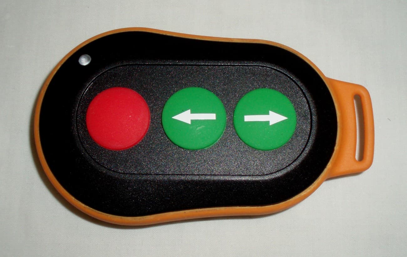
QUUSWTX01
Oct 09, 2012REMOTE CONTROL TRANSMITTER
Equipment Class
DSC - Part 15 Security/Remote Control Transmitter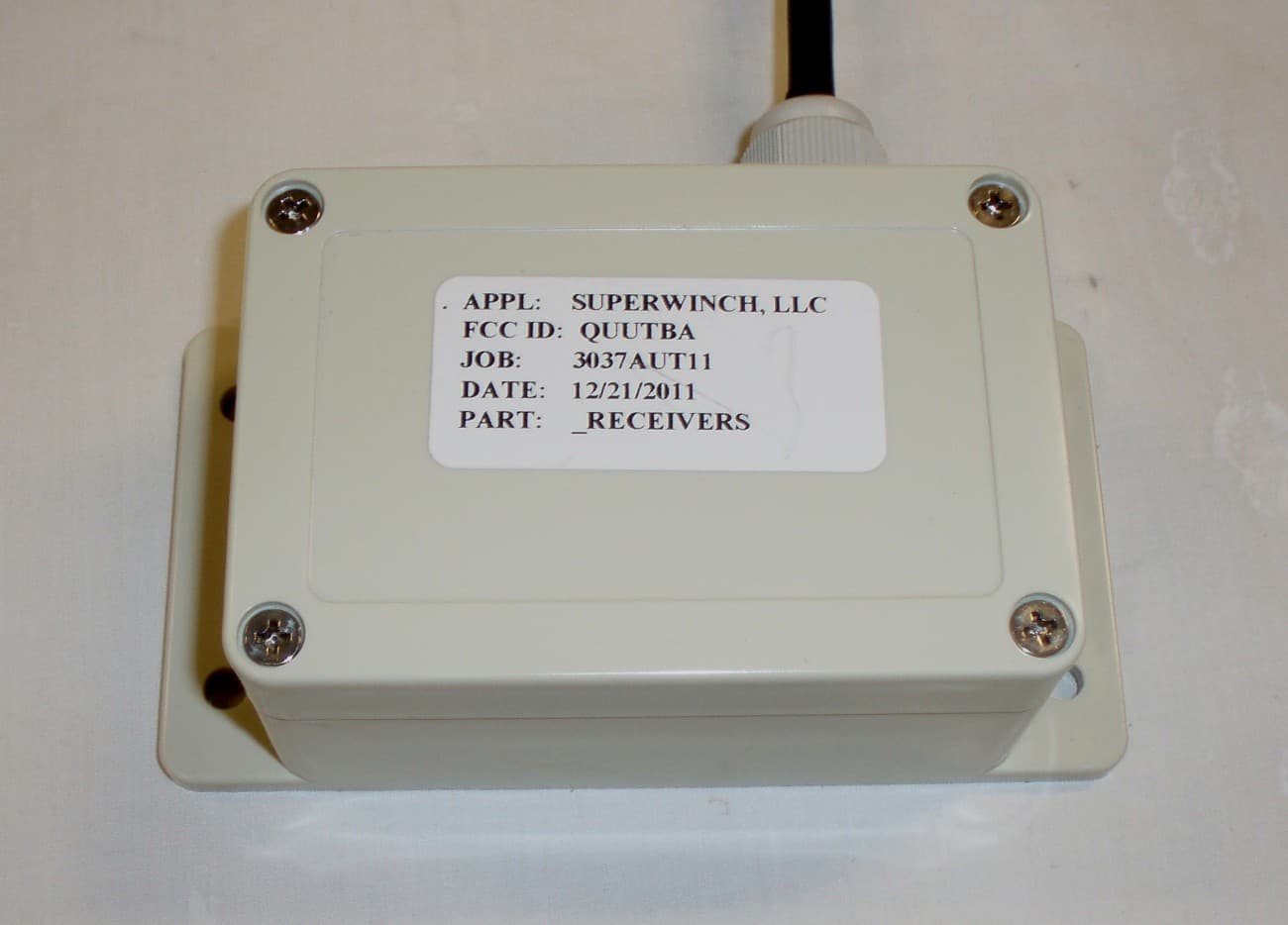
QUUSWRX01
Aug 29, 2012RECEIVER
Equipment Class
CYY - Communications Receiver used w/Pt 15 Transmitter
QUUWK37
Dec 08, 2004Wireless Utility Winch
Equipment Class
CRR - Superregenerative Receiver
QUUWK4
Oct 12, 2004Wireless Power Drive Control
Equipment Class
CRR - Superregenerative Receiver
QUUWRX4
Apr 18, 2004Remote Controller - RX
Equipment Class
CRR - Superregenerative Receiver