QUUSWRX01RECEIVER
Superwinch, LLC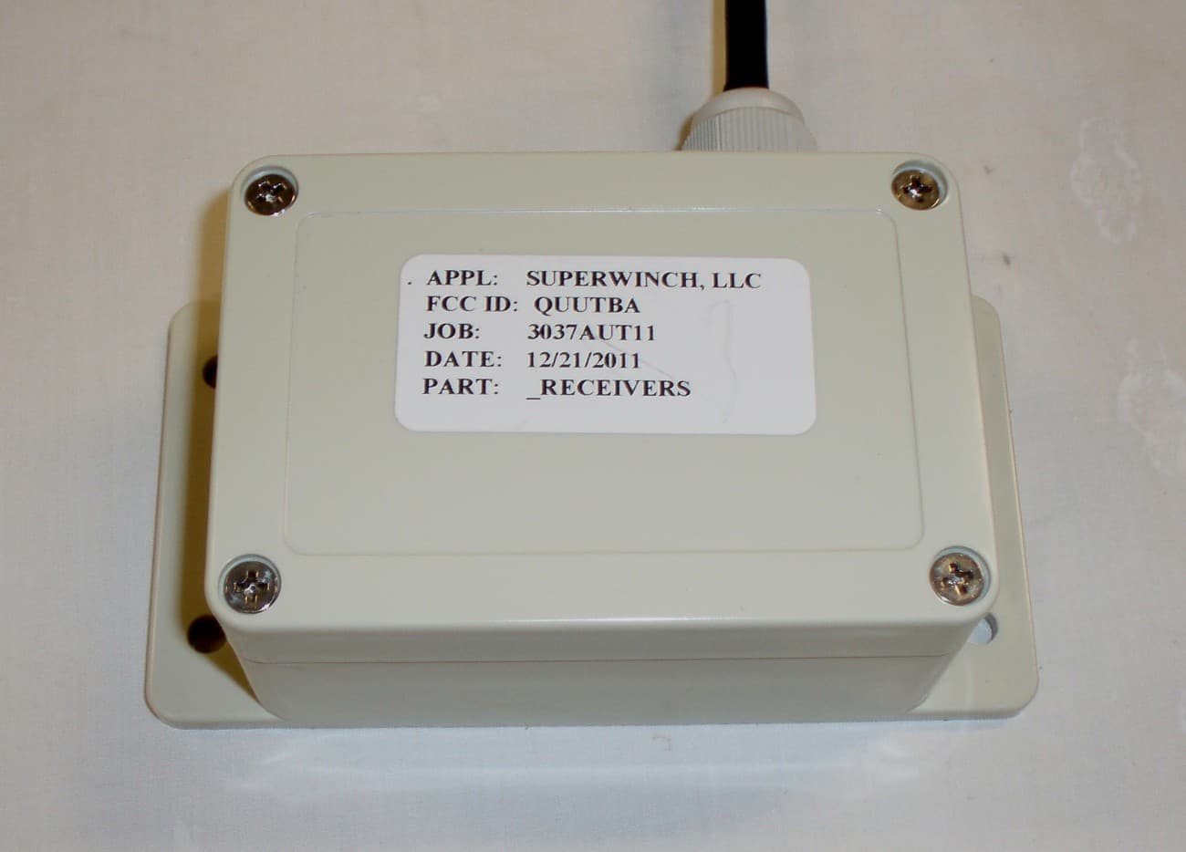
Click to zoom
Application Details
- Equipment Class
- CYY - Communications Receiver used w/Pt 15 Transmitter
- Date of Grant
- Aug 29, 2012
- Application Purpose
- Original Equipment
- Date of Application
- Aug 29, 2012
- Equipment Note
- RECEIVER
- Frequency Range
- 433.92000000 - 433.92000000
- Company
- Superwinch, LLC
- Country
- United States
Documents & Files
Document Text
Text extracted from the exhibit documents filed with the FCC. Open a document above to read the original.
Users Manual
*+ # i Superwinch LLC. 359 Lake Road Dayville, CT 06241, USA tel: 1.860.928.7787 fax: 1.860.963.0811 [email protected] www.superwinch.com Superwinch LTD. Union Mine Road Tavistock, Devon PL19 0NS England tel: +44 (0) 1822 614101 fax: + 44 (0) 1822 615204 [email protected] 98-17449 Rev - 01/24/2012 OWNER’S MANUAL READ AND UNDERSTAND THIS MANUAL BEFORE INSTALLATION AND OPERATION OF YOUR SUPERWINCH PRODUCT CAUTION ! TM WIRELESS REMOTE CONTROL 1 SPANISH WARNING ! CERTUS WIRELESS REMOTE SYSTEM – CONSUMER VERSION Read and understand the manual thoroughly before installing or using the radio remote control. General Information The system operates on a frequency of 433MHZ and utilizes frequency modulation generally known as FM technology. While an FM signal is much less susceptible to electrical interference than an AM signal, there can never be total protection against outside interference. Interference can result from the turning on and off of electronic equipment and can come from proximity to industrial equipment and types of computer equipment. The greatest range will be achieved if the receiver is not enclosed in metal. SAFETY PRECAUTIONS The responsibility for safe installation and operation of this system ultimately rests with you, the operator. Read and understand all safety precautions and operating instructions before installing and operating the system. Careless system operation can result in serious injury and/or property damage. Throughout this manual, you will find notations with the following headings: Indicates an imminently hazardous situation which, if not avoided, will result in death or serious injury. Indicates a potentially hazardous situation which, if not avoided, could result in death or serious injury. Indicates a potentially hazardous situation which, if not avoided, may result in minor or moderate injury. This notation is also used to alert against unsafe practices. CAUTION ! DANGER ! Read Owner's Manual Note: Indicates additional information in the installation and operation procedures of your wireless remote control. The following symbols on the product and in the Owners manual are used: WARNING ! 2 Improper installation or improper use of the remote unit by the user could result in injury or destruction of property. Keep this manual for future reference. SPANISH Misuse or abuse of this equipment could result in injury to the user or others and/or damage to property. The control will be brought to a stop if: 1. the red power button is activated 2. system encounters the same frequency from an outside source 3. five minutes go by since the last transmission These safety features are engineered into the system to protect personnel and equipment and should never be changed, taken out or bypassed. If an emergency situation arises immediately press the red power button on the transmitter see (Fig. 1) 1. Never leave the transmitter unattended. 2. The transmitter is only to be used where there is a clear view of the operating machinery. 3. Do not use more than one transmitter for one receiver box. If you own or purchase a backup transmitter it is important to stow the second transmitter securely. When the system is first put into use, the backup unit should be tested then have its battery removed and the unit should be stored in a secure place to avoid accidental operation, which may result in serious injury or death. 4. Both the transmitter housing and buttons should be checked on a regular basis and, if damaged, the transmitter should be taken out of use. 5. In an emergency situation, pressing the red stop button should immediately activate the stop relay in the receiver. Remove power to the machine. 3 Fig. 1 LED 1 Power Button SPANISH ! AVERTISSEMENT SPANISH Programming the Transmitter Note: Transmitters supplied with the unit are pre-programmed at the factory - DO NOT RE-PROGRAM THEM. Should a new transmitter be purchased it will require programming. To program, follow the instructions below: NOTE: Each of the three (3) buttons needs to be programmed individually OPERATION INSTRUCTIONS RED Power Button Green Button 1 Green Button 2 LED 1 (Fig. 2) Front of Transmitter Green LED Red LED Program Green Button 1: • Press the learn button (See Fig.3 below) 1 time. Wait for the red LED on receiver to flash 1 time. • Press green button 1 on the transmitter and release. • Re-press green button 1 on the transmitter. The red LED on receiver will now flash to indicate that learning is complete for green button 1. Learn Button (Fig.3) 4 The transmitter has one red LED light, see (Fig. 2) which glows when any one of the buttons is depressed; this shows the receiver is sending a signal to the receiver. 1. To use the wireless system, the operator first activates the system by pressing the red power button on the transmitter; a green LED on the receiver will glow as the system is now in operational mode and ready for use. 2. To deactivate the wireless system, press the red power button and the green LED on the receiver turns off as the system is now in standby mode. 3. The power button always has priority and will override all buttons so that it will put the system into standby mode. 4. If the system is idle for 5 minutes or longer, the system will deactivate and go into standby mode and will need to be activated prior to use. Program Red Power Button: • Press the learn button 1 time Wait for the red LED on receiver to flash 1 time • Press the learn button 1 more time Wait for the red LED on receiver to flash 2 times • Press the learn button 1 more time Wait for the red LED on receiver to flash 3 times • Press the red button on the transmitter and release • Re-press the red button on the transmitter The red LED on receiver will now flash to indicate that learning is complete for the red button Your transmitter is now programmed and ready for use Program Green Button 2: • Press the learn button 1 time Wait for the red LED on receiver to flash 1 time • Press the learn button 1 more …
Text truncated - open the document above for the full version.
Cover Letter(s)
CONFIDENTIALITY REQUEST for Certification Service in USA Federal Communication Commission Equipment Authorization Division, Application Processing Branch 7435 Oakland Mills Road Columbia, MD 21048 6/4/2012 TO WHOM IT MAY CONCERN Pursuant to Paragraphs §0.457 and 0.459 of the Commission’s Rules (47 C.F.R.) and Section §552(b)(4) of the Freedom of Information Act, we requests confidentiality for the following products: FCC ID Model name QUUSWRX01 SWRX01 For the product stated above, we request permanent confidentiality for exhibits which contain Operational Description, Block Diagram, and Schematics information. The above exhibits contain our trade secrets and proprietary information that could be of benefit to our competitors. If you have any questions, please feel free to contact me at the address shown below. Sincerely, Scott Saccoccio Name: Scott Saccoccio Company: Superwinch, LLC Address: 359 Lake Road, Putnam, CT 06241 Phone: (860) 928-7787 Fax: (860) 928-1143 Email: [email protected]
External Photos
APPLICANT: SUPERWINCH, LLC FCC ID: QUUSWRX01 EXTERNAL PHOTOS
ID Label/Location Info
For Receiver Rear Face: www.superwinch.com FCC ID: QUUSWRX01 IC: 5101A-SWRX01 Model #: 98-40299 For Transmitter Rear Face: www.superwinch.com FCC ID: QUUSWTX01 IC: 5101A-SWTX01 Model #: 98-40299
Internal Photos
APPLICANT: SUPERWINCH, LLC FCC ID: QUUSWRX01 INTERNAL PHOTOS RX FRONT VIEW RX REAR VIEW RX FRONT WITH RX MODULE RX REAR WITH RX MODULE RX MODULE – FRONT VIEW RX MODULE – REAR VIEW
Operational Description
DS RDF-3 July ‘11 2008 REG No 277 4001, England. Page 1 RF RECEIVER DECODER RDF1 Description The RDF1 is a complete FM receiver and decoder module in one, providing a complete radio system with up to four digital outputs and single serial data output when used with an RF Solutions FIREFLY, HORNET or 205 series Handheld transmitters. Dependant on the transmitter, a system using the RDF1 can achieve up to 200m range. The RDF1 module consists of a front end super-heterodyne receiver and an embedded microcontroller which decodes the RF string for a compatible transmitter and outputs to 4 telemetry lines and as serial data. The module has an easy-to-use 'LEARN' facility, and is capable of storing up to 40 pairings within its internal in non volatile memory (EEPROM). Part Numbers Part Number Description Compatible Transmitters and Encoders RDF1-433 Superhetrodyne Receiver Decoder FM, 433MHz FIREFLY HORNET 205 RF800/803 Series Chipsets * Range is dependent on the transmitter used Features • Complete FM Receiver and Decoder. • Small Form Factor • Range up to 200 Metres* • Easy Learn Transmitter Feature. • Learns 40 transmitter Switches • 4 Digital and 1 Serial Data outputs • Outputs, Momentary or Latching. • Minimal external components • Direct Led Drive Shows Data Reception • Secure Data Protocol • 5V Supply • CE Compliant for Licence Free Use • Compatible with • RF800 and 803 series Encoder IC’s • HORNET, FIREFLY, and 205 series transmitters Applications • Remote Control • Radio Telemetry • RFID DS RDF-3 July ‘11 2008 REG No 277 4001, England. Page 2 RF RECEIVER DECODER RDF1 Pin Description Pin No Name I/O Description 1 VCC - The power supply needs to be a stable regulated 5V with <10mV ripple 2 GND - RF ground 3 RFIN I RF input (Antenna) Connection 4 – 6 N/C N/A Not Connected 7 GND - RF Ground Connection 8 RSSI O Received signal strength indicator 9 VCC - 5 V Power Supply 10 N/C N/A Not Connected 11 GND - Ground Connection 12 N/C N/A Not Connected 13 LRN/LED I/O Multi Function Pin This input is used to set the decoder module to ‘Learn Mode’ and for the ‘Erase Function’ it is also used to drive the Status LED. 14 OP4 O These outputs normally Low and are asserted High when the relevant inputs of a learnt transmit device are asserted. 15 OP3 O 16 OP2 O 17 OP1 O 18 MOMLTCH2 I These pins are read on power up to set the action of outputs 1-4. Momentary action is set by a connection to ground. Latching is set using open circuit. See table on P4 19 MOMLTCH1 I 20 SERIAL O In normal run mode this pin outputs serial data on reception of a valid data string. VCC GND ANTGND RSSI VCC N/C GND N/C LRN/LED OP4OP3OP2OP1 SERIAL 10 11 12 13 14 15 16 17 1820 987 321 19 MOM/LTCH2MOM/LTCH1 DS RDF-3 July ‘11 2008 REG No 277 4001, England. Page 3 RF RECEIVER DECODER RDF1 RDF1 Application Circuit The RDF1 requires only the addition of the following components 1. A ‘Learn’ switch which is used in the process of learning a transmitter/encoder to the decoder and also to initiate erasure of encoder information. 2. An LED and series Resistor 470 Ohm which indicates the status of the learn process, the erase process and also data reception status. 3. Two Option links (LK1 and LK2) which configure the action of the digital outputs. Custom versions of this product are available, please contact our sales department for further details Compatibility with RF Solutions Transmitters: All RDF1 receiver decoders are compatible with the HORNET, FIREFLY, and 205 series of ready to operate handheld transmitters. This enables a designer to integrate a remote control function easily into an application using a ready made transmitter. DS RDF-3 July ‘11 2008 REG No 277 4001, England. Page 4 RF RECEIVER DECODER RDF1 System and Functional operation Digital Data Outputs Each RF Solutions transmitter contains a secure serial identity. When a switch is pressed, the transmitter emits a unique secure RF signal. The Receiver can learn this signal and allocate it to any of its output(s). Any transmitter switch may be paired to one or many of a receiver’s outputs, Many transmitters switches may be paired to a single receiver output. This enables One transmitter switch to control many receivers outputs, or, Many transmitters switches to control one receiver output The only limitation is that each receiver has a maximum capacity of 40 pairings, (can be from the same or any number of transmitters). Hint: the same transmitter may be taught to any number of receivers to create ‘master keys’. Learn: Learn Mode activation is achieved by pulling this input to GND briefly Paring Procedure (Learning a Transmitter Switch to RDF1 digital output) (as application circuit) 1. Select the receiver output to learn onto: a. Briefly operate the RDF1 Learn switch once b. The Learn LED will flash once to indicate output 1 is selected c. After the LED stops flashing, press the Learn switch again to select the next output channel. d. Repeat step c until the required output is selected. 2. Operate the Transmitter button that you want to learn to the selected RDF1 output. 3. The Learn LED will then illuminate, operate the same transmitter button again. 4. The Learn LED will then flash to indicate learning is complete. Erase Mode: Erase Mode is achieved by pulling this input to GND for >8 seconds. This causes the internal EEPROM to be erased of all pre-learnt Transmitter pairings. Digital Output Configuration: Momentary or Latching These high impedance inputs are used to set the digital outputs to momentary or latched actions Mom: This output is valid for the duration of valid key press of the transmitter switch Latch: This output changes state on each valid transmitter switch press. Link Positions Digital Outputs Link1 Link2 O/P 1 O/P 2 O/P 3 O/P 4 Closed Closed Mom Mom Mom Mom Closed Open Mom Mom Latch Latch Open Closed Mom Latch Latch Latch Open Open Latch Latch Latch Latch Outputs Outputs are digital CMOS/TTL (PIC Micro) with a series 220Ω protection resistor. Outputs…
Text truncated - open the document above for the full version.
Test Report
FCC PART 15 B SUBPART B RECEIVER TEST REPORT Applicant SUPERWINCH, LLC Address 359 LAKE ROAD DAYVILLE CT 06241 FCC ID QUUSWRX01 Model 98-40299 Product Description RECEIVER Date Sample Received 12/21/2011 Date Tested 01/03/2012 Tested By JOE SCOGLIO Approved By MARIO R. DE ARANZETA Report Number 3037AUT11TestReport_Certification.pdf Test Results PASS FAIL THE ATTACHED REPORT SHALL NOT BE REPRODUCED EXCEPT IN FULL WITHOUT THE WRITTEN APPROVAL OF TIMCO ENGINEERING, INC. 849 NW State Road 45 Newberry, Fl 32669 USA Phone: 888.472.2424 or 352.472.5500 Fax: 352.472.2030 Email: [email protected] Website: www.timcoengr.com Certificate # 0955-01 APPLICANT: SUPERWINCH, LLC FCC ID: QUUSWRX01 REPORT: O:\S\SUPERWINCH\3037AUT11\3037AUT11TestReport_Certification.DOC Page 2 of 10 rev 2 mdea 09.20.2008 TABLE OF CONTENTS GENERAL REMARKS.............................................................................................................. 3 REPORT SUMMARY ............................................................................................................... 4 TEST ENVIRONMENT ............................................................................................................. 4 TEST SETUP SUMMARY ......................................................................................................... 4 DUT SPECIFICATION ............................................................................................................. 5 TEST EQUIPMENT LIST.......................................................................................................... 6 TEST PROCEDURES .............................................................................................................. 7 RADIATED SPURIOUS EMISSIONS ......................................................................................... 8 POWER LINE CONDUCTED INTERFERENCE .......................................................................... 9 RADIATED EMISSIONS TEST SETUP PHOTO ....................................................................... 10 APPLICANT: SUPERWINCH, LLC FCC ID: QUUSWRX01 REPORT: O:\S\SUPERWINCH\3037AUT11\3037AUT11TestReport_Certification.DOC Page 3 of 10 rev 2 mdea 09.20.2008 GENERAL REMARKS The attached report shall not be reproduced except in full without the written permission of Timco Engineering Inc. The test results relate only to the items tested. Summary The device under test does: fulfill the general approval requirements as identified in this test report not fulfill the general approval requirements as identified in this test report Attestations This equipment has been tested in accordance with the standards identified in this test report. To the best of my knowledge and belief, these tests were performed using the measurement procedures described in this report. All instrumentation and accessories used to test products for compliance to the indicated standards are calibrated regularly in accordance with ISO 17025 requirements. Certificate # 0955-01 I attest that the necessary measurements were made, under my supervision, at: Timco Engineering Inc. 849 NW State Road 45 Newberry, Fl 32669 Authorized Signatory Name: Mario de Aranzeta C.E.T. Compliance Engineer/ Lab. Supervisor Date: 01/17/2012 APPLICANT: SUPERWINCH, LLC FCC ID: QUUSWRX01 REPORT: O:\S\SUPERWINCH\3037AUT11\3037AUT11TestReport_Certification.DOC Page 4 of 10 rev 2 mdea 09.20.2008 REPORT SUMMARY Disclaimer The test results only relate to the item tested. Applicable Rule(s) Pt 15.109, Pt 15.107, ANSI C63.4: 2003 TEST ENVIRONMENT Test Facility Timco Engineering, Inc. 849 NW State Road 45 Newberry, FL 32669 USA. Test Condition in the laboratory Temperature: 26ºC Relative humidity: 50% TEST SETUP SUMMARY Test Setup Diagram/ Description The DUT was placed on the turntable per setup per ANSI C63.4: 2003. A test set up photo is provided for clarification. Deviation from the standard/procedure No deviation Modification of DUT No modification APPLICANT: SUPERWINCH, LLC FCC ID: QUUSWRX01 REPORT: O:\S\SUPERWINCH\3037AUT11\3037AUT11TestReport_Certification.DOC Page 5 of 10 rev 2 mdea 09.20.2008 DUT SPECIFICATION DUT Description RECEIVER FCC ID QUUSWRX01 DUT Power Source 110–120Vac/50– 60Hz DC Power Battery Operated Exclusively Test Item Prototype Pre-Production Production Type of Equipment Fixed Mobile Portable Laboratory Test Conditions Temperature: 26ºC Humidity: 55% Modifications to DUT: No Yes (explanation below) APPLICANT: SUPERWINCH, LLC FCC ID: QUUSWRX01 REPORT: O:\S\SUPERWINCH\3037AUT11\3037AUT11TestReport_Certification.DOC Page 6 of 10 rev 2 mdea 09.20.2008 TEST EQUIPMENT LIST Device Manufacturer Model Serial Number Cal/Char Date Due Date 3-Meter Semi- Anechoic Chamber Panashield N/A N/A Listed 5/10/10 5/10/12 AC Voltmeter HP 400FL 2213A14499 CAL 6/12/11 6/12/13 Antenna: Active Loop ETS-Lindgren 6502 00062529 CAL 9/23/10 9/23/12 Frequency Counter HP 5385A 2730A03025 CAL 8/17/11 8/17/13 Hygro- Thermometer Extech 445703 0602 CAL 6/15/11 6/15/13 Modulation Analyzer HP 8901A 3435A06868 CAL 7/18/11 7/18/13 Digital Multimeter Fluke FLUKE-77 35053830 CAL 9/9/11 9/9/13 Analyzer Tan Tower Preamplifier HP 8449B-H02 3008A00372 CAL 10/28/11 10/28/13 Analyzer Tan Tower Quasi- Peak Adapter HP 85650A 3303A01690 CAL 10/28/11 10/28/13 Analyzer Tan Tower RF Preselector HP 85685A 3221A01400 CAL 10/28/11 10/28/13 Analyzer Tan Tower Spectrum Analyzer HP 8566B Opt 462 3138A07786 3144A20661 CAL 10/28/11 10/28/13 Antenna Electro metrics LPA-25 1122 5/04/2011 5/04/2013 APPLICANT: SUPERWINCH, LLC FCC ID: QUUSWRX01 REPORT: O:\S\SUPERWINCH\3037AUT11\3037AUT11TestReport_Certification.DOC Page 7 of 10 rev 2 mdea 09.20.2008 TEST PROCEDURES Power line conducted Emission: The test procedure used was ANSI C63.4-2003. The spectrum was scanned from 0.15 to 30 MHz. Radiation Interference: The test procedure used was ANSI C63.4-2003 using a spectrum analyzer with a preselector. The bandwidth of the spectrum analyzer was 100 kHz with an appropriate sweep speed. The…
Text truncated - open the document above for the full version.
Contact Information
Applicant
Scott Saccoccio(Senior Design Engineer)
Test Firm
Timco Engineering, Inc.Bruno Clavier
Technical Specifications
| # | Rule Parts | Frequency Range | Power Output |
|---|---|---|---|
| 1 | 15B | 433.92 MHz - 433.92 MHz | - |
Other Applications from Superwinch, LLC
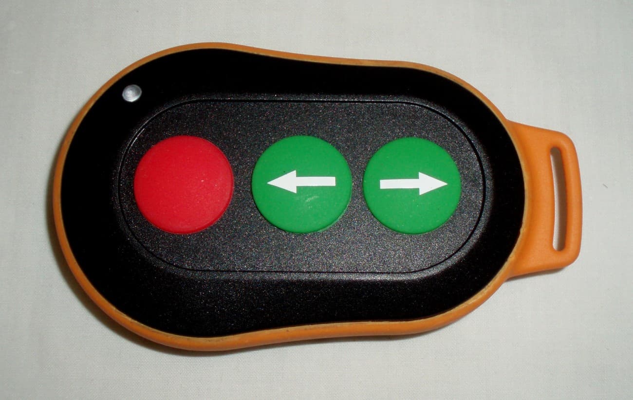
QUUSWTX01
Oct 09, 2012REMOTE CONTROL TRANSMITTER
Equipment Class
DSC - Part 15 Security/Remote Control Transmitter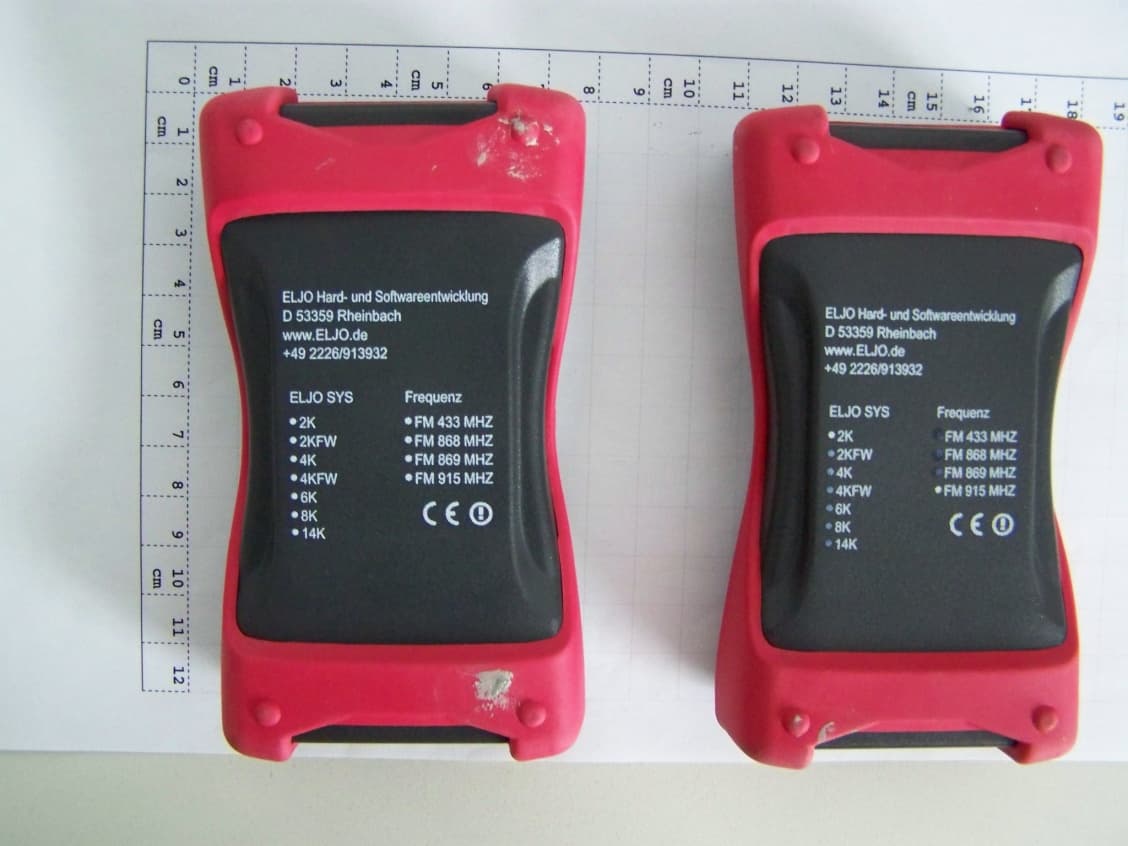
QUUI28CT
Aug 16, 2011Remote Control
Equipment Class
DXX - Part 15 Low Power Communication Device Transmitter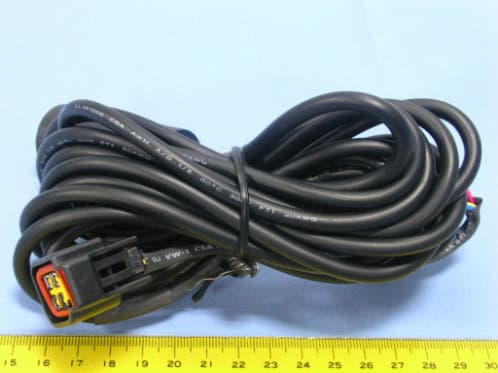
QUUWK37
Dec 08, 2004Wireless Utility Winch
Equipment Class
CRR - Superregenerative Receiver
QUUWK4
Oct 12, 2004Wireless Power Drive Control
Equipment Class
CRR - Superregenerative Receiver
QUUWRX4
Apr 18, 2004Remote Controller - RX
Equipment Class
CRR - Superregenerative Receiver