QVE4DELTARemote Control Device Transmitter
SMK Manufacturing, Inc.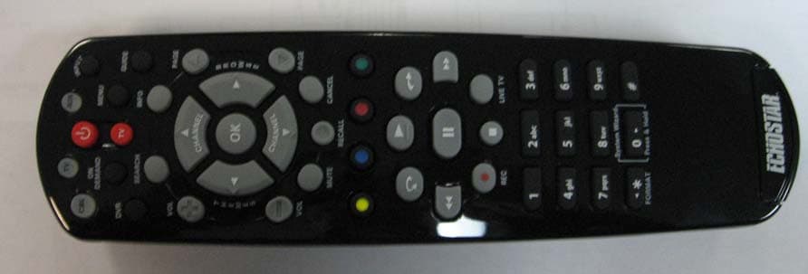
Click to zoom
Application Details
- Equipment Class
- DTS - Digital Transmission System
- Date of Grant
- Mar 30, 2011
- Application Purpose
- Original Equipment
- Date of Application
- Mar 30, 2011
- Equipment Note
- Remote Control Device Transmitter
- Frequency Range
- 2425.00000000 - 2475.00000000
- Company
- SMK Manufacturing, Inc.
- Country
- United States
Documents & Files
Document Text
Text extracted from the exhibit documents filed with the FCC. Open a document above to read the original.
Users Manual
For all your customer needs, call the Customer Service Center at 1-800-333-DISH(3474) 176842
Users Manual
C-1 Accessing the System Wizard Refer to page 12 for information on System Wizard Press MENU, select Settings and then System Wizard. OR
Users Manual
C-2 Separate the key from the remote by inserting your thumbnail or a coin in the crease. Remove the key by grasping at the bottom. Insert the key face up and slide into place. Pull the remote battery cover off. Confirm your remote has the green number 1 key installed. Note: If you will be using the green TV1 key that comes already installed in your remote, skip this step and proceed with the next step (Insert the Batteries). Verify the Key 1 Insert the Batteries 2 1 4 2 3 1 Replace the remote battery cover. Insert 4 AAA batteries, making sure to match the plus (+) ends with the plus markings on the battery case. 2 Quick Setup
Users Manual
C-3 Quick Setup Confirm that your remote operates your receiver by pressing remote buttons. If this is not working, repeat step 5. If the remote is still not linked to your ViP922 receiver, see page 10 in this guide. Making the Remote Work With Your Receiver 3 6 Turn your ViP922 receiver and TV on, and select SYSTEM INFO on the receiver front panel. Confirm that you see the System Information screen. Press and release SAT on your remote. After a few seconds, you will hear a tone, and the remote will be listed on the screen. 3 2 1 5 4 Verify this key is installed, and continue with step 2. Verify the remote antenna is installed on the back of the receiver. REMOTE ANTENNA
Users Manual
C-4 Quick Setup Select TV Code and then follow the on-screen instructions to enter your TV’s device code. Set Up the Remote to Control Your TV 12 3 4 To set up the remote control to operate a TV, you can select a Device Code (see instructions on page 3). Your ViP922 DVR has a large database of Device Codes for other equipment. Press the POWER button to turn the TV on and try other buttons to make sure the code works. If you want to try another code, start over from step 3. Press MENU, select Settings and then Remote Control. Turn your TV on. 4
Users Manual
Quick Setup/Operation C-5 Placing Your Remote in Limited Mode Use the arrow button to highlight Enabled and then select it. 2 3 Highlight and select Save. 1 Select the Limited Mode option. To take the remote out of Limited Mode, highlight Disabled instead of Enabled in step 3. Limited Mode locks out all the TV mode operations except for TV power, Mute, and Volume. This prevents you from accidentally tuning away from satellite programming. Press MENU, select Settings and then Remote Control.
Users Manual
Receiver Power & TV Power Top button turns the receiver on/off, Bottom button turns the TV on/off Programming required (see C-4) Input Press once for Input Operation Remote Operation SAT Mode SAT Control TV volume Programming required (see C-4) Volume & Mute Buttons To use the features described in this section, make sure you are in SAT mode by pressing the SAT Mode button. Note: Some features may not be available depending on your receiver model. Page Buttons Page up/down in menus and Guide Program Guide Display current and future satellite program listings Arrows/Select Buttons Channel up/down, navigate through menus and select a desired option Browse See what is on other channels while watching TV View Satellite Programming Exit out of any menu/ guide and go back to viewing live TV Number Buttons Enter a channel number to change to that channel System Wizard Press and hold to sync remote and receiver data Dish Explore DISH On Demand options Receiver Menu Access receiver features and settings Themes Search for programs using Themes Recall Go back to last channel viewed Info Get info on programs Search Search for a program Jump Move cursor to another screen area Digital Video Recorder (DVR) Buttons Pause live TV and play or record programming Picture-In-Picture (PIP) Buttons Watch two separate programs at once (in Solo PIP Mode) Format Format the picture to the desired width to match the program you are viewing C-6 Press this button for SAT Mode
Users Manual
C-8 Operation Remote Operation TV Mode To use the features described in this section, make sure you are in TV mode by pressing the TV Mode button. Remote programming is required. See C-4 for instructions. Note: If you have programmed the remote in Limited Mode (C-5), only the TV Power, Mute and Volume buttons will control your TV. TVTV Note: Remote operation is different on DISH Network TVs. See your DISH Network TV User's Guide for proper operation. Press this button for TV Mode Up/Down Arrow Buttons Channel up/down on TV Number Buttons Enter a desired channel number on TV TV Menu Access menu features available on some TVs Input Switch between TV inputs Mute Turn TV volume on or off Recall Go back to last TV channel viewed Picture-In-Picture (PIP) Buttons Display PIP features on some TVs with PIP capabilities C-7 Volume Control TV volume Receiver Power & TV Power Turn the TV on/off Programming required (see C-4) Programming required (see C-4)
Users Manual
C-8 Operation Remote Operation DVD Mode DVD To use the features described in this section, make sure you are in DVD mode by pressing the DVD Mode button. You can use this mode to operate your VCR instead of a disc player. Remote programming is required. See page 2 for instructions. Press this button for DVD Mode Input Switch VCR between its TV & VCR mode DVD/VCR Power & TV Power Top button turns the DVD player/VCR power on and off, Bottom button turns the TV on and off Number Buttons Enter a channel number for VCR or a chapter title on a DVD Record Record on a videotape Back Rewind a videotape or reverse a DVD Stop Stop playing a DVD, stop playing or recording a videotape Up/Down Arrow Buttons Channel up/down on VCR Pause Pause a videotape or DVD FWD Forward a videotape or DVD Play Play a videotape or DVD
Users Manual
Remote Control User Guide Remote Control User Guide
Users Manual
To read out your remote codes, see page 9 for instructions. If your remote is in Limited Mode (see page C-6), then only Volume and Mute buttons work in TV mode. Remote Key Auxiliary Equipment Code 1
Users Manual
1 REMOTE CONTROL OVERVIEW Use this full-function remote control to operate the DISH Network ViP® 922 SlingLoaded™ DVR receiver. Also, you can program this remote control to operate most popular brands of audio/video equipment like a TV, a DVD/BD player (or VCR), or an audio receiver/ amplifier. See Setting Up the Remote to Work With Your Equipment on page 3. Note: This remote control may support features not used by your receiver. Also, new features may be added by future software updates. USING THIS GUIDE This guide makes it easy to set up and use your remote control. By now you’ve noticed that the cover contains information on quick setup and remote control operation. The rest of the guide contains in-depth information to help you get the most from your remote control, including controlling other equipment like TVs, audio devices, and DVD/BD players or VCRs. REMOTE CONTROL MODES Use the remote control’s mode buttons to set the remote to the correct mode for the equipment. Be sure to program the remote control to operate the other equipment as described starting on page 2. To change the mode, press and release the button for the equipment you want to control. The mode button lights up (green for SAT mode, red for TV or AUX mode) for about three seconds to show you’ve set the remote to that device mode. Great Idea: Whenever you finish using other equipment (TV, DVD/VCR, etc.), be sure to put the remote back in SAT mode. 2 If you program the remote control to operate other equipment, refer to page C-6 and the following for remote-control operation instructions: •POWER, INPUT, MUTE, and VOLUME remote buttons are used to control your TV when it is programmed in TV mode. •The same buttons your DVR uses when in SAT mode are used to control a DVD/BD player (or VCR) when this equipment is programmed in DVD mode (or alternatively, in AUX mode). •SELECT, MUTE, VOLUME, and POWER remote buttons may be used to control your stereo equipment (for example, when an audio receiver or amplifier is programmed in AUX mode). HOW THE REMOTE COMMUNICATES All remote controls used with ViP922 receivers use radio frequency (RF) signals to control the receiver and IR signals to control any other equipment you have programmed. •Make sure that the RF remote antenna for the ViP922 is attached correctly to the receiver’s back panel R EMOTE ANTENNA input so it can receive the RF remote signals. •RF signals travel relatively long distances and can go through walls and other solid objects. For example, the TV2 remote can control the receiver from any area of the house. Link only the remote(s) you are using with your ViP922 receiver (see page 10). •IR signals, used in TV, DVD, and AUX device modes, travel up to 40 feet in a straight line of sight, and cannot go through walls or other solid objects. Point the remote directly at the equipment you want to control with no objects blocking the signal path. SETTING UP FOR OTHER EQUIPMENT The following section contains detailed instructions on how to set up this remote control to operate a TV and other audio/video equipment you may have (such as a DVD/BD player or VCR, audio receiver or amplifier). You can program the remote control by completing the tasks described in Setting Up the Remote to Work With Your Equipment on page 3. COMBINATION EQUIPMENT (FOR EXAMPLE, TV/DVD) When setting up the remote control to operate combination equipment, such as a TV with built-in DVD or VCR, program the remote control in one mode, and then repeat the procedure in the other device mode. For example, to program the remote control to operate a TV/DVD player 3 (or TV/VCR), follow the instructions to program the remote to operate the TV using its code, and then repeat those instructions for the DVD/ BD player or VCR in AUX mode using its code. Press the TV mode button to use the combination device’s TV functions, or the AUX mode button to use DVD/BD (or VCR) functions. SETTING UP THE REMOTE TO WORK WITH YOUR E QUIPMENT You can set up the remote control to operate other equipment using the following steps and the modes as shown on page 1. InstructionsAdditional Information 1Turn your equipment on.Use your equipment’s front panel buttons or its own original remote control. 2Press POWER on your ViP922 DVR front panel or linked remote and access Remote Control settings. Press MENU and select the Settings tile. Then from the Settings screen, select Remote Control. 3Select the TV Code, DVD Code, or AUX Code option, as applicable. You can also change which device controls volume and mute functions. Switching Between TV and Amplifier Volume Control on page 8 Select TV Code to program the remote to control your TV when in TV mode. Select DVD Code to program the remote to control a disc player, or select AUX Code to program the remote to control another audio device when in AUX mode. 4If you know the brand name of your device, but not its code, then select the Look Up Code option and continue with step 5. If you know the four-digit code for your device, select the Enter Code option and follow the steps for Entering Equipment Codes on page 5. Your ViP922 DVR receiver’s software maintains a database of device codes for controlling many types and brands of equipment. Updates to the software may add more device codes to this database. Note that the three-digit device codes used by other DISH Network remote controls cannot be used. 4 5Scroll the Sort By: (or Aux Device:) list to position the option you wish to select within the blue highlight bar. Then highlight your device’s name in the Brand: list and select Next. If the brand is not listed, see Entering Equipment Codes on page 5. If there is no equipment code for your device right now, you can check to see if one has been added after your receiver’s next scheduled software update. 6The next screen displays the number of device codes available for the selected brand, and which code is ready for you to test. There may only be two or three device codes for your …
Text truncated - open the document above for the full version.
Users Manual
Table of Contents Quick Setup Verifying the Key ................................................................... C-2 Inserting the Batteries ........................................................... C-2 Linking Your Remote Control ................................................ C-3 Operation Setting Up the Remote to Control Your TV ........................... C-4 Placing Your Remote in Limited Mode.................................. C-5 Remote Operation in SAT/TV/DVD Modes ................... C-6, 7, 8 Remote Control Overview......................................................... 1 Using this Guide ....................................................................... 1 Remote Control Modes ............................................................. 1 How the Remote Communicates .............................................. 2 Setting Up for Other Equipment................................................ 2 Combination Equipment (for example, TV/DVD) ...................... 2 Setting Up the Remote to Work With Your Equipment ............. 3 Entering Equipment Codes ....................................................... 5 Switching Between TV and Amplifier Volume Control .............. 8 Viewing Equipment Codes........................................................ 9 Avoiding RF Interference .......................................................... 9 Remote Button Shortcuts........................................................ 10 Locating a Lost Remote ...........................................................11 Using the System Wizard ........................................................11 Troubleshooting ...................................................................... 13 Limited Warranty..................................................................... 15
Users Manual
This device complies with Industry Canada licence-exempt RSS standard(s). Operation is subject to the following two conditions: (1) this device may not cause interference, and (2) this device must accept any interference, including interference that may cause undesired operation of the device. Le présent appareil est conforme aux CNR d'Industrie Canada applicables aux appareils radioexempts de licence. L'exploitation est autorisée aux deux conditions suivantes : (1) l'appareil ne doit pas produire de brouillage, et (2) l'utilisateur de l'appareil doit accepter tout brouillage radioélectrique subi, même si le brouillage est susceptible d'en compromettre le fonctionnement
Cover Letter(s)
Nemko Canada Inc 303 River Road Ottawa, Ontario, Canada K1V 1H2 Attn: Director of Certification FCC ID: QVE4DELTA Authority to Act as Agent On our behalf, I appoint Alan Laudani of Nemko USA Inc., 11696 Sorrento Valley Rd, San Diego, CA, USA to act as our agent in the preparation of this application for equipment certification. I certify that submitted documents properly describe the device or system for which equipment certification is sought. I also certify that each unit manufactured, imported or marketed, as defined in Federal Communication Commission’s regulations will have affixed to it a label identical to that submitted for approval with this application. For instances where our authorized agent signs the application for certification on our behalf, I acknowledge that all responsibility for complying with the terms and conditions for certification, as specified by Nemko Canada Inc, still resides with with SMK of 1055 Tierra Del Rey Suite H, Chula Vista, CA 910910. Agency agreement expires: July 1, 2011
Cover Letter(s)
DATE Nemko 11696 Sorrento Valley Rd. San Diego CA, 92121 USA Re: Request of Confidentiality for FCC ID: QVE4DELTA Pursuant to Sections 0.457(d)(I)(ii) and 0.459 of the Commission’s Rules, the Applicant hereby requests confidential treatment of information accompanying as outlined below: Schematics, Parts List, Operating Description, Block Diagrams The above materials contain trade secrets and proprietary information not customarily released to the public. The public disclosure of these matters might be harmful to the Applicant and provide unjustified benefits to its competitors. The Applicant understands that pursuant to Rule 0.457(d)(I)(ii), disclosure of this Application and all accompanying documentation will not be made before the date of the Grant for this Application. Sincerely, Agency agreement expires: July 1, 2011
Internal Photos
no shields were needed
Test Report
Nemko USA, Inc. 11696 Sorrento Valley Rd., Suite F San Diego, CA 92121-1024 Phone (858) 755-5525 Fax (858) 452-1810 CERTIFICATION TEST REPORT T ITLE 47 CFR 15 SUBPART C, 15.247 IC RSS-210, I SSUE 8, DECEMBER 2010 For The Wireless Remote Control Model: 184057 FCC ID: QVE4DELTA IC: 3683B-4DELTA PREPARED FOR: SMK Manufacturing 12264 El Camino Real, Ste. 203 San Diego, CA 92130 Prepared on: March 21, 2011 Report Number: 2011 031025216 FCC Project Number: 1025216 NEx Number: 168271 Total Pages: 39 Nemko USA, Inc. 11696 Sorrento Valley Road, Suite F, San Diego, CA 92121 Phone (858) 755-5525 Fax (858) 452-1810 DATE DOCUMENT NAME DOCUMENT # PAGE March 21, 2011 Model 184057 Certification Test Report FCC ID: QVE4DELTA IC: 3683B-4DELTA 2011 031025216-FCC 2 of 39 DOCUMENT HISTORY REVISION DATE COMMENTS - March 21, 2011 Prepared By: Jim Owen - March 21, 2011 Initial Release: Alan Laudani NOTE: Nemko USA, Inc. hereby makes the following statements so as to conform to Chapter 10 (Test Reports) Requirements of ANSI C63.4 (2003) “Methods and Measurement of Radio-Noise Emissions from Low-Voltage Electrical and Electronic Equipment in the Range of 9 kHz to 40 GHz”: o The unit described in this report was received at Nemko USA, Inc.'s facilities on March 14, 2011. o Testing was performed on the unit described in this report on March 11, 2011. o The Test Results reported herein apply only to the Unit actually tested, and to substantially identical Units. o This report does not imply the endorsement of the Federal Communications Commission (FCC), Industry Canada, NVLAP or any other government agency. This Report is the property of Nemko USA, Inc., and shall not be reproduced, except in full, without prior written approval of Nemko USA, Inc. However, all ownership rights are hereby returned unconditionally to SMK Manufacturing, and approval is hereby granted to SMK Manufacturing, and its employees and agents to reproduce all or part of this report for any legitimate business purpose without further reference to Nemko USA, Inc. Nemko USA, Inc. 11696 Sorrento Valley Road, Suite F, San Diego, CA 92121 Phone (858) 755-5525 Fax (858) 452-1810 DATE DOCUMENT NAME DOCUMENT # PAGE March 21, 2011 Model 184057 Certification Test Report FCC ID: QVE4DELTA IC: 3683B-4DELTA 2011 031025216-FCC 3 of 39 TABLE OF CONTENTS DOCUMENT HISTORY .................................................................................................................................... 2 CERTIFICATION............................................................................................................................................... 4 1. ADMINISTRATIVE DATA AND TEST SUMMARY ............................................................................ 5 1.1.ADMINISTRATIVE DATA................................................................................................................................. 5 1.2.TEST SUMMARY............................................................................................................................................. 5 2. SYSTEM CONFIGURATION .................................................................................................................. 6 2.1.DESCRIPTION AND METHOD OF EXERCISING THE EUT................................................................................... 6 2.2.SYSTEM COMPONENTS AND POWER CABLES.................................................................................................. 6 2.3.DEVICE INTERCONNECTION AND I/O CABLES................................................................................................ 7 2.4.DESIGN MODIFICATIONS FOR COMPLIANCE................................................................................................... 7 2.5.TECHNICAL SPECIFICATIONS OF THE EUT...................................................................................................... 8 3. DESCRIPTION OF TEST SITE AND ENVIRONMENT ........................................................................ 9 3.1.DESCRIPTION OF TEST SITE............................................................................................................................ 9 3.2.TEST ENVIRONMENT...................................................................................................................................... 9 4. DESCRIPTION OF TESTING METHODS ............................................................................................ 10 4.1.INTRODUCTION............................................................................................................................................. 10 4.2.CONFIGURATION AND METHODS OF MEASUREMENTS FOR CONDUCTED EMISSIONS.................................... 10 4.3.CONFIGURATION AND METHODS OF MEASUREMENTS FOR RADIATED EMISSIONS....................................... 11 5. TEST RESULTS ...................................................................................................................................... 12 5.1.RADIATED EMISSIONS.................................................................................................................................. 12 5.2.DUTY CYCLE FACTOR.................................................................................................................................. 16 5.3.BANDWIDTH................................................................................................................................................. 18 5.4.OUT-OF-BAND EMISSIONS / RADIATED EMISSIONS WITHIN RESTRICTED BANDS.......................................... 22 5.5.BAND EDGE MEASUREMENTS...................................................................................................................... 27 5.6.MINIMUM 6DB RF BANDWIDTH.................................................................................................................. 29 5.7.MAXIMUM PEAK OUTPUT POWER......................................................................................…
Text truncated - open the document above for the full version.
Contact Information
Applicant
Tom Fukushima(Engineering Manager)
Technical Contact
SMK USALeon W Gateno
[email protected]619-216-6425
1055 Tierra Del Rey, Suite H · Chula Vista, California · United States
Non-Technical Contact
SMK USATom Fukushima
[email protected]619-216-6424
Test Firm
Nemko USA, Inc. - San Diego EMC DivisionJan Blomgren
[email protected]760-444-3500
Technical Specifications
| # | Rule Parts | Frequency Range | Power Output |
|---|---|---|---|
| 1 | 15C | 2.42 GHz - 2.48 GHz | 1.44 mW |
Other Applications from SMK Manufacturing, Inc.
QVE4SYDN
Mar 31, 2015Remote Control with 2.4GHz ISM radio for a set top box
Equipment Class
DTS - Digital Transmission System
QVEFSK2LC
Nov 08, 2012Remote Control Device Transmitter
Equipment Class
DSC - Part 15 Security/Remote Control Transmitter
QVEFSRC01
Dec 01, 2011Scoop pointer remote and wireless presenter
Equipment Class
DXX - Part 15 Low Power Communication Device Transmitter
QVEFSRX01
Dec 01, 2011USB receiver for Scoop pointer remote and Scoop wireless presenter
Equipment Class
DXX - Part 15 Low Power Communication Device Transmitter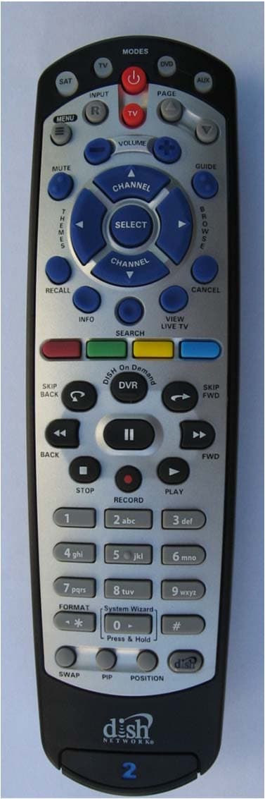
QVEFSK4U2
Aug 29, 2011Remote Control
Equipment Class
DXX - Part 15 Low Power Communication Device Transmitter