QVEFSK2LCRemote Control Device Transmitter
SMK Manufacturing, Inc.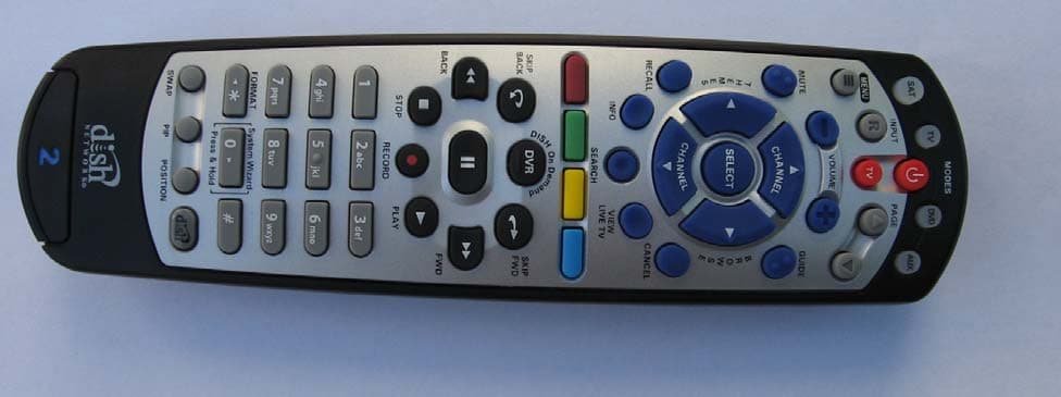
Click to zoom
Application Details
- Equipment Class
- DSC - Part 15 Security/Remote Control Transmitter
- Date of Grant
- Nov 08, 2012
- Application Purpose
- Original Equipment
- Date of Application
- Nov 08, 2012
- Equipment Note
- Remote Control Device Transmitter
- Frequency Range
- 369.50000000 - 394.30000000
- Company
- SMK Manufacturing, Inc.
- Country
- United States
Documents & Files
Document Text
Text extracted from the exhibit documents filed with the FCC. Open a document above to read the original.
Users Manual
Remote User Guide Safety Instructions You must keep safety in mind while using this device. Keep these and any other instructions for future reference. Observe Warnings: Carefully follow all warnings on the device and in the operating instructions. Heat: Do NOT place the device near heat sources such as radiators, stoves, heat registers, or other appliances that produce heat. Care and Use Cleaning: Do NOT use liquid, abrasive, solvent, or aerosol cleaners. Use a damp cloth for cleaning. When Not in Use: Remove the batteries if this device is to be left unattended or unused for a long period of time. Refer servicing to qualified personnel when a solid object or liquid has fallen onto or into the device. Do NOT attempt to service this device. Refer all servicing to qualified personnel. Opening covers other than the battery cover will void the warranty. Publishing Information Copyright © 2011. EchoStar Technologies L.L.C., Englewood, Colorado 80112. All rights reserved. The information in this User Guide may change without notice. Revisions may be issued to tell you about such changes. Send comments or questions about this User Guide to [email protected] or Technical Publications, EchoStar Technologies L.L.C, 90 Inverness Drive Circle East, Englewood, Colorado 80112. Document Number: 180532 Printed in DISH Network is a registered trademark of DISH Network L.L.C. All product names, trade names, or corporate names mentioned in this User Guide are acknowledged to be the proprietary property of the registered owners. 1 Configuring the 20.1 Remote Configuring the 21.1 Remote The 20.1 remote does not require any configuration. Go to Insert the Batteries (page 2). 1 2 3 4 Pull the remote battery cover off. Decide whether to use IR or UHF signals for the remote. Use UHF signals if you do not have a clear line of sight between the remote and the receiver. Set UHF/IR SWITCH to either UHF or IR. If your remote has a blank, black key, continue to Insert the Batteries on page 2. If your remote shows a “1” or a “2” on the bottom, you can pull out this key and flip it to the other number (2 to 1 and 1 to 2). To separate the key from the remote, insert your thumbnail or a coin in the crease. Remove the key by grasping at the bottom. Insert the key you wish to use to designate the remote and slide into place. Usually a 1 = TV1 and a 2 = TV2. For remotes showing the blank, black key, leave this key as it is. Complete the following steps to configure your remote. 2 Insert the Batteries Pull the remote battery cover off. Insert 4 AAA batteries, making sure to match the plus (+) ends with the plus markings on the battery case. Replace the remote battery cover. 1 2 3 3 Using System Wizard Note: Not all receivers support System Wizard. If System Wizard does not appear, continue with page 4 or page 5 to make your remote work with your receiver. Use System Wizard initially to set up the remote to work with the receiver. System Wizard can also store/ restore your remote settings. Note: If your batteries are low, replace them before beginning. Press and hold 0 until System Wizard message appears. Make sure the remote and receiver are in line of sight. If first time in System Wizard, follow instructions provided. When green checkmark displays, select Advanced to store/ restore remote settings. Follow the on-screen options. Select Continue to return to Live TV. 1 2 3 4 4 Making 20.1 and 21.1 IR Remote Work with Receiver Turn your receiver and TV on, and press SYSTEM INFO on the front of the receiver. Confirm that you see the System Info screen. Press RECORD on your remote. The receiver then matches the remote’s address. Confirm that your remote operates your receiver by pressing remote buttons. If this is not working, go back to step 3. 1 2 3 4 1 For 20.1 and 21.1 IR Use the following instructions to configure your remote while using IR signals. Note: Use these instructions if your receiver does not support System Wizard. 5 Making 21.1 UHF Remote Work with Receiver Verify the UHF antenna is installed on the back of the receiver. Turn your receiver and TV on, and press SYSTEM INFO on the front of the receiver. Confirm that you see the System Info screen. Press RECORD on your remote. The remote address will probably change on the screen. Confirm that your remote operates your receiver by pressing remote buttons. If this is not working, go back to step 4. 3 2 1 4 5 For 21.1 UHF Use the following instructions if you have configured your remote to use UHF signals. 1 1 Note: Use these instructions if your receiver does not support System Wizard. 6 SAT Mode To use the features described in this section, make sure you are in SAT mode by pressing the SAT Mode button. Note: Some features may not be available depending on your receiver model. SAT Power & TV Power Top button turns the receiver on/off Bottom button turns the TV on/off Press this button for SAT Mode Volume and Mute Buttons Control TV volume Programming required Recall Return to last TV channel viewed Picture-In-Picture (PIP) Buttons Watch two separate programs at once (in Single Mode) Number Buttons Enter a channel number or navigate through menus Receiver Menu Access receiver features and settings Input Press once for Input Press and hold for Recover Themes Search for programs using Themes Info Get info on programs Search Search for a program Shortcut Keys (for future use) Digital Video Recorder (DVR) Buttons Pause live TV and play or record programming Format Format the picture to the desired width to match the program you are viewing System Wizard Press and hold to fix remote control issues and sync data DishHOME Explore interactive TV features Arrow/Select Buttons Channel up/down, navigate through menus, and select a desired option View Satellite Programming Exit out of any menu/guide and return to viewing live TV Cancel Return to previous menu or to watching a program Browse See what is on other channels while watching TV Program Guide Display current and f…
Text truncated - open the document above for the full version.
Cover Letter(s)
Federal Communications Commission 7435 Oakland Mills Road Columbia, MD 21046 USA I FCC ID: QVEFSK2LC Product Name: 2 Way LC Authority to Act as Agent to the Federal Communications Commission On our behalf, I appoint Leon Gateno of SMK USA, Inc. to act as agent in the preparation of this application for equipment authorization to the Federal Communications Commission. I certify that submitted Exhibits properly describe the device or system for which equipment authorization is sought. I also certify that each unit manufactured, imported or marketed, as defined in the Commission's regulations will have affixed to it a label identical to that submitted for approval with this application. APPLICANT ANTI-DRUG ABUSE CERTIFICATION: In signing this letter, Applicant certifies that, in the case of an individual applicant, he or she is not subject to a denial of federal benefits, that includes FCC benefits, pursuant to Section 5301 of the Anti-Drug Abuse Act of 1988, 21 U.S.C. 853(a), or, in the case of a - individual applicant (e.g. corporation, partnership or other unincorporated association), no party to the application is subject to a denial of federal benefits, that includes FCC benefits, pursuant to that section. For the definition of a "party" for these purposes, see 47 CFR 1.2002(b). Dated this 18 th Day of August, 2012 Agency agreement expiration date: 1 July 2013 Company:SMK By: Tom Fukushima Title: Engineering G.M. Telephone: 619-216-6400 Applicant: SMK
Cover Letter(s)
Federal Communications Commission 7435 Oakland Mills Road Columbia, MD 21046 USA FCC ID: QVEFSK2LC Product Name: 2 Way LC Authority to Act as Agent to the Federal Communications Commission On our behalf, I appoint Alan Laudani of Nemko USA, Inc. to act as agent in the preparation of this application for equipment authorization to the Federal Communications Commission. I certify that submitted Exhibits properly describe the device or system for which equipment authorization is sought. I also certify that each unit manufactured, imported or marketed, as defined in the Commission's regulations will have affixed to it a label identical to that submitted for approval with this application. APPLICANT ANTI-DRUG ABUSE CERTIFICATION: In signing this letter, Applicant certifies that, in the case of an individual applicant, he or she is not subject to a denial of federal benefits, that includes FCC benefits, pursuant to Section 5301 of the Anti-Drug Abuse Act of 1988, 21 U.S.C. 853(a), or, in the case of a non-individual applicant (e.g. corporation, partnership or other unincorporated association), no party to the application is subject to a denial of federal benefits, that includes FCC benefits, pursuant to that section. For the definition of a "party" for these purposes, see 47 CFR 1.2002(b). Dated this 18 Day of October , 2012 Agency agreement expiration date: 10 July 2013 Company: SMK By: Leon Gateno Title: SR RF Engineer Telephone: 619-216-6425 Applicant: SMK
Cover Letter(s)
8/18/12 Equipment Autorisation Division Federal Communications Commission 7435 Oakland Mills Road Columbia, MD 21046 FCC ID: QVEFSK2LC Product Name: 2 Way LC Request for Confidentiality Pursuant to Sections 0.457 and 0.459 of the commissions rules, we hereby request that the following documents be held confidential: • Schematics • Block diagram • BOM These materials contain trade secrets and proprietary information and are not customarily released to the public. The public disclosure of this information might be harmful to the company and provide unjustified benefits to our competitors. Dated this 18 th Day of August 2012 RF Engineer Applicant: Echostar
Operational Description
Confidential Page 19/24/2012 1055 Tierra Del Rey Chula Vista, CA91910 Operational Description PAGE: 1 OF 5 DATE: 9/21/12 REVISIONS REV DESCRIPTION CHECK ENG DATE 1.0 Release Leon Gateno 9/21/12 REMARKS: Confidential Page 29/24/2012 1055 Tierra Del Rey Chula Vista, CA91910 Operational Description PAGE: 2 OF 5 DATE: 9/21/12 INDEX 1 INTRODUCTION .......................................................................................................................................... 3 2 BLOCK DIAGRAM ....................................................................................................................................... 4 3 MODULATION ............................................................................................................................................. 5 4 FREQUENCY OF OPERATION................................................................................................................... 5 5 TIMING .......................................................................................................................................................... 5 6 NETWORKING ............................................................................................................................................. 5 7 OUTPUT POWER.......................................................................................................................................... 5 8 ANTENNA ..................................................................................................................................................... 5 Confidential Page 39/24/2012 1055 Tierra Del Rey Chula Vista, CA91910 Operational Description PAGE: 3 OF 5 DATE: 9/21/12 1 INTRODUCTION This document will describe the operation of the 2 Way LC remote. The remote operates mainly as a RF remote. The document is divided into the following sections: a) Block Diagram b) Modulation c) Timing d) Networking e) Frequency of operation f) Output Power g) Antenna Abbreviations RF IC Radio frequency integrated circuit. IC Integrated Circuit. TX transmitter RCVR receiver. Confidential Page 49/24/2012 1055 Tierra Del Rey Chula Vista, CA91910 Operational Description PAGE: 4 OF 5 DATE: 9/21/12 2 BLOCK DIAGRAM The following is a Block Diagram for the remote: Vdd in The block diagram has two sections the BB and the RF. The BB consists of a small ASIC that is used to set up registers and control words. These are used for timing purposes. The BB shares the same reference as the RF, which is a 10MHz crystal. The RF section consists of the transmitter in the RFIC, the exception of the 10 MHz crystal, internal matching networks, external filter and antenna. User does not have access to adjusting the frequency, power levels. This is done at the factory. Confidential Page 59/24/2012 1055 Tierra Del Rey Chula Vista, CA91910 Operational Description PAGE: 5 OF 5 DATE: 9/21/12 3 MODULATION There is two modulation schemes used in these system is OOK, the other is Infrared. 4 FREQUENCY OF OPERATION The frequency of operation is from 369.5, 375.3, 388.3, 394.3 MHz. It will operate at only one frequency at a time. It will never operate on two frequencies. 5 TIMING The signal is a bursting signal. The duty cycle is 38 ms in 100 ms. 6 NETWORKING For this specific application there is no networking. The unit will communicate with a specific setup box. 7 OUTPUT POWER The max output power is 0 dBm. 8 ANTENNA The antenna is a small loop antenna. The pattern of the antenna is omni directional / donut shape. This antenna is a trace antenna and cannot be removed. It does not have an RF connector.
Test Report
Nemko USA, Inc. 2210 Faraday Avenue, Suite 150, Carlsbad, CA 92008 Phone (760) 444-3500 Fax (760) 444-3005 FCC ID: QVEFSK2LC Report Number: 2012 06207734-1 FCCTR Specification: FCC Part 15 Subpart C, 15.231 Page 1 of 27 Certification Test Report In Accordance With: FCC Part 15 Subpart C, 15.231 Applicant: SMK Manufacturing 1055 Tierra del Rey Chula Vista, CA 91910 Equipment Under Test (EUT): Settop Box Remote Control Model: LC 2way FCC ID: QVEFSK2LC Tested By: Nemko USA Inc. 2210 Faraday Avenue, Suite 150 Carlsbad, CA 92008 Authorized By: Alan Laudani, EMC/RF Test Engineer Test Report Number: 2012 11218099 FCCTR Date: October 22, 2012 Project Number 1029704 NEX Number 218099 Total Number of Pages: 27 Nemko USA, Inc. 2210 Faraday Avenue, Suite 150, Carlsbad, CA 92008 Phone (760) 444-3500 Fax (760) 444-3005 FCC ID: QVEFSK2LC Report Number: 2012 06207734-1 FCCTR Specification: FCC Part 15 Subpart C, 15.231 Page 2 of 27 Applicant Affirmation Leon Gateno representing SMK Manufacturing hereby affirms: a) That he/she has reviewed and concurs that the test shown in this report are reflective of the operational characteristics of the device for which certification is sought; b) That the device in this test report will be representative of production units; c) That all changes (in hardware and software/firmware) to the subject device will be reviewed. d) That any changes impacting the attributes, functionality or operational characteristics documented in this report will be communicated to the body responsible for approving (certifying) the subject equipment. Leon Gateno Printed name of official Signature of official 1055 Tierra del Rey August 28, 2012 Address Date 619-216-6400 [email protected] Telephone number Email address of official NOTE—This affirmation must be signed by the responsible party before it is submitted to a regulatory body for approval. Nemko USA, Inc. 2210 Faraday Avenue, Suite 150, Carlsbad, CA 92008 Phone (760) 444-3500 Fax (760) 444-3005 FCC ID: QVEFSK2LC Report Number: 2012 06207734-1 FCCTR Specification: FCC Part 15 Subpart C, 15.231 Page 3 of 27 Section 1. Summary of Test Results 1.1 General All measurements are traceable to national standards These tests were conducted on a sample of the equipment for the purpose of demonstrating compliance with Part 15; Subpart C. Radiated tests were conducted is accordance with ANSI C63.4-2003. Radiated emissions are made on an open area test site. A description of the test facility is on file with the FCC. The assessment summary is as follows: Apparatus Assessed: Settop Box Remote Control Model: LC 2way Specification: FCC Part 15 Subpart C, 15.231 Date Received in Laboratory: August 23, 2012 Compliance Status: Complies Exclusions: None Non-compliances: None Nemko USA, Inc. 2210 Faraday Avenue, Suite 150, Carlsbad, CA 92008 Phone (760) 444-3500 Fax (760) 444-3005 FCC ID: QVEFSK2LC Report Number: 2012 06207734-1 FCCTR Specification: FCC Part 15 Subpart C, 15.231 Page 4 of 27 1.2 Report Release History REVISION DATE COMMENTS - November 2, 2012 Prepared By: Andreas Gillmeier - November 2, 2012 Initial Release: Alan Laudani Note that the results contained in this report relate only to the items tested and were obtained in the period between the date of initial receipt of samples and the date of issue of the report. This test report has been completed in accordance with the requirements of ISO/IEC 17025. Nemko USA Inc. authorizes the applicant to reproduce this report provided it is reproduced in its entirety and for use by the Company’s employees only. Any use which a third party makes of this report, or any reliance on or decisions to be made based on it, are the responsibility of such third parties. Nemko USA Inc. accepts no responsibility for damages, if any, suffered by any third party as a result of decisions made or actions based on this report. Andreas Gillmeier , Sr. EMC/Wireless Engineer Alan Laudani, RF/EMC Test Engineer Nemko USA, Inc. 2210 Faraday Avenue, Suite 150, Carlsbad, CA 92008 Phone (760) 444-3500 Fax (760) 444-3005 FCC ID: QVEFSK2LC Report Number: 2012 06207734-1 FCCTR Specification: FCC Part 15 Subpart C, 15.231 Page 5 of 27 TABLE OF CONTENTS Applicant Affirmation ................................................................................................... 2 Section 1. Summary of Test Results ...................................................................... 3 1.1 General ........................................................................................................... 3 1.2 Report Release History ................................................................................... 4 Section 2: Equipment Under Test ................................................................................ 6 2.1 Theory of Operation ........................................................................................ 6 2.2 Technical Specifications of the EUT ............................................................... 6 Section 3: Test Conditions ........................................................................................... 7 3.1 Specifications ................................................................................................. 7 3.2 Deviations From Laboratory Test Procedures ................................................ 7 3.3 Test Environment ........................................................................................... 7 3.4 Test Equipment .............................................................................................. 8 Section 4: Observations ............................................................................................... 8 4.1 Modifications Performed During Assessment ................................................. 8 4.2 Record Of Technical Judgements .................................................................. 8 4.3 EUT Parameters Affecting Compliance .......................................................... 8 4.4 Tests De…
Text truncated - open the document above for the full version.
Contact Information
Applicant
Tom Fukushima(Engineering Manager)
Technical Contact
SMK USALeon W Gateno
[email protected]619-216-6425
1055 Tierra Del Rey, Suite H · Chula Vista · United States
Non-Technical Contact
SMK USATom Fukushima
[email protected]619-216-6424
Test Firm
Nemko USA, Inc. - San Diego EMC DivisionJan Blomgren
[email protected]760-444-3500
Technical Specifications
| # | Rule Parts | Frequency Range | Power Output |
|---|---|---|---|
| 1 | 15.231 | 369.5 MHz - 394.3 MHz | - |
Other Applications from SMK Manufacturing, Inc.
QVE4SYDN
Mar 31, 2015Remote Control with 2.4GHz ISM radio for a set top box
Equipment Class
DTS - Digital Transmission System
QVEFSRC01
Dec 01, 2011Scoop pointer remote and wireless presenter
Equipment Class
DXX - Part 15 Low Power Communication Device Transmitter
QVEFSRX01
Dec 01, 2011USB receiver for Scoop pointer remote and Scoop wireless presenter
Equipment Class
DXX - Part 15 Low Power Communication Device Transmitter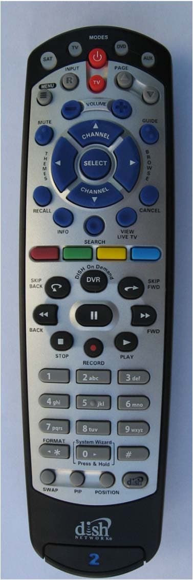
QVEFSK4U2
Aug 29, 2011Remote Control
Equipment Class
DXX - Part 15 Low Power Communication Device Transmitter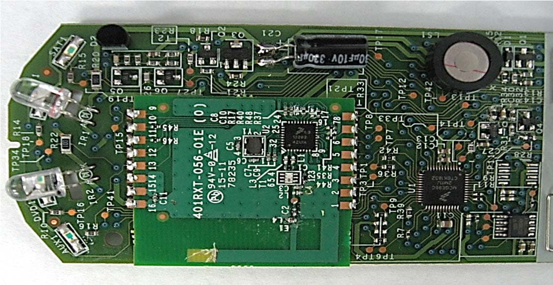
QVE4XIPR
Aug 10, 2011Remote Control
Equipment Class
DXX - Part 15 Low Power Communication Device Transmitter