QVE4SYDNRemote Control with 2.4GHz ISM radio for a set top box
SMK Manufacturing, Inc.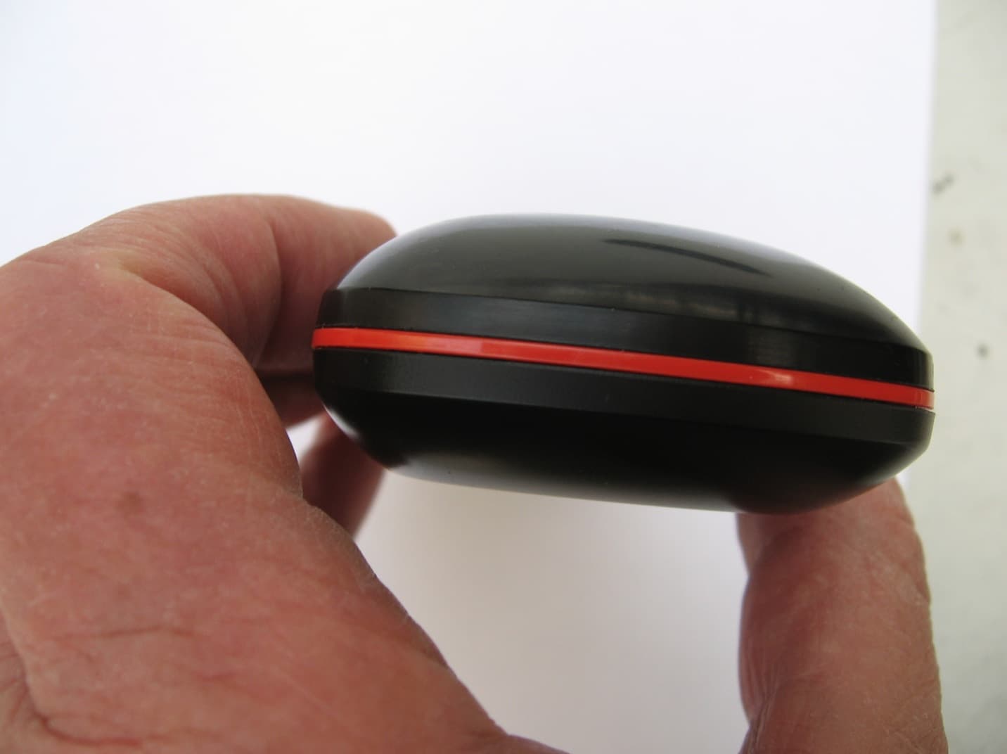
Click to zoom
Application Details
- Equipment Class
- DTS - Digital Transmission System
- Date of Grant
- Mar 31, 2015
- Application Purpose
- Original Equipment
- Date of Application
- Mar 31, 2015
- Equipment Note
- Remote Control with 2.4GHz ISM radio for a set top box
- Frequency Range
- 2425.00000000 - 2475.00000000
- Company
- SMK Manufacturing, Inc.
- Country
- United States
Documents & Files
Document Text
Text extracted from the exhibit documents filed with the FCC. Open a document above to read the original.
Users Manual
REMOTE USER GUIDE Safety Instructions You must keep safety in mind while using this device. Keep these and any other instructions for future reference. Observe Warnings: Carefully follow all warnings on the device and in the operating instructions. Heat: Do NOT place the device near heat sources such as radiators, stoves, heat registers, or other appliances that produce heat. Care and Use Cleaning: Do NOT use liquid, abrasive, solvent, or aerosol cleaners. Use a damp cloth for cleaning. When Not in Use: Remove the batteries if this device is to be left unattended or unused for a long period of time. Refer servicing to qualified personnel when a solid object or liquid has fallen onto or into the device. Do NOT attempt to service this device. Refer all servicing to qualified personnel. Opening covers other than the battery cover will void the warranty. Publishing Information Copyright © 2015. EchoStar Technologies L.L.C., Englewood, Colorado 80112. All rights reserved. The information in this User Guide may change without notice. Revisions may be issued to tell you about such changes. Send comments or questions about this User Guide to [email protected] or Technical Publications, EchoStar Technologies L.L.C, 90 Inverness Drive Circle East, Englewood, Colorado 80112. Document Number: 206231 Printed in DISH is a registered trademark of DISH Network L.L.C. All product names, trade names, or corporate names mentioned in this User Guide are acknowledged to be the proprietary property of the registered owners. 1 Insert the Batteries Push the tab toward the top of the remote to release the battery door latch and then lift the battery door from the remote. Insert 2 AA batteries, making sure to match the plus (+) ends with the plus markings on the battery case. Replace the remote battery cover. 1 2 3 R E M OT E A N T E N NA SYSTEM INFO SYS INFO 2 Pairing Remote to the Hopper® or Joey® Receiver Verify the antenna is installed on the back of your Hopper receiver. Joey receivers have an internal antenna. Turn your receiver and TV on, and press SYSTEM INFO on the front panel. Confirm that you see the System Info screen. Press and release the SAT button on your remote (on the side of the remote). Wait until you hear a tone and see the remote listed on the screen. After pairing, you should hear a series of ascending tones. Confirm that your remote operates your receiver by pressing remote buttons. If this is not working, go back to step 4. 3 2 1 4 5 For the remote to work with either a Hopper® or Joey® receiver, it must be paired. Use the following procedure to pair the remote. Joey: OR Hopper: 3 SAT/TV/AUX Mode indicator lights up when sending signals in that mode For the remote to work with either a Hopper® or Joey® receiver, it must be paired. Use the following procedure to pair the remote. CH Channel up/down, navigate through menus, and select a desired option Skip Forward/ Forward Press and release to skip forward 10 seconds in a program. Press and hold to forward through the program. Skip Back/ Back Press and release to skip back 10 seconds in a program. Press and hold to reverse the program. Back/Live TV Return to previous menu. Press and hold to return to viewing live TV Pause/Play Pauses or plays a live or recorded program SAT Mode To use the features described in this section, make sure you are in SAT mode by pressing the SAT Mode button. Note: Some features may not be available depending on your receiver model. Power & TV Power Left button turns the receiver on/off Right button turns the TV on/off Vol and Mute Buttons Control TV volume Programming required Recall Return to previously viewed TV channel(s) 123/abc Displays the number pad in the touchpad. Press and hold to navigate the on-screen alpha keypad Home Access receiver features and settings Options Opens contextual options menu for each screen Apps Displays the Apps menu DVR Displays list of recorded programs Info/Help Retrieve info on programs and set a timer. Press and hold for contextual help Guide Display current and future satellite program listings Microphone Captures voice when remote is in voice command mode 4 SAT Mode, continued To use the features described in this section, make sure you are in SAT mode by pressing the SAT Mode button. Note: Some features may not be available depending on your receiver model. Input Swaps the tuner Microphone Activates voice control screen Backlight Backlights the remote buttons Hot Key/ Shortcut Button Use this button to set up a shortcut Press this button for SAT Mode SAT LED lights up 5 123 Enter a channel number from the touchpad TV Mode To use the features described in this section, make sure you are in TV mode by pressing the TV Mode button. Remote programming is required. Note: The remote has Limited Mode enabled, which means only the Volume, Mute, and TV Power buttons work in TV Mode (see Enabling or Disabling Limited Mode on page 19). Note: Some features may not be available depending on your TV model. Mute Turn TV volume on or off Recall Return to last TV channel viewed Input Switch between TV inputs (available only for certain makes and models of TVs) Channel Up/Down Channel up/ down on the TV Volume Control TV volume Press this button for TV Mode Power & TV Power Left button turns the receiver on/off Right button turns the TV on/off TV Menu Access menu features available on some TVs 6 DVR Functions • Displays a list of recorded programs. • Plays a live or recorded program. • Pauses a live or recorded program. • Press SKIP BACK to skip back about 10 seconds in a program. Press and hold SKIP BACK to reverse the program four times as fast as normal play. Press BACK twice to reverse at 15 times normal speed, three times to reverse at 60 times normal speed, and four times to reverse at 300 times normal speed. The on- screen bar shows how far you’ve gone. For a live program, you can only reverse back to the last channel change or back one hour, whichever occurs first. • Press SKIP FWD…
Text truncated - open the document above for the full version.
External Photos
FCC ID: QVE4SYDN Report No.: SC1411276 Page 1 of 5 FCC ID: QVE4SYDN Report No.: SC1411276 Page 2 of 5 FCC ID: QVE4SYDN Report No.: SC1411276 Page 3 of 5 FCC ID: QVE4SYDN Report No.: SC1411276 Page 4 of 5 FCC ID: QVE4SYDN Report No.: SC1411276 Page 5 of 5
ID Label/Location Info
FCC ID: QVE4SYDN Report No.: SC1411276 Page 1 of 1 Label location
Internal Photos
FCC ID: QVE4SYDN Report No.: SC1411276 Page 1 of 9 FCC ID: QVE4SYDN Report No.: SC1411276 Page 2 of 9 FCC ID: QVE4SYDN Report No.: SC1411276 Page 3 of 9 FCC ID: QVE4SYDN Report No.: SC1411276 Page 4 of 9 FCC ID: QVE4SYDN Report No.: SC1411276 Page 5 of 9 FCC ID: QVE4SYDN Report No.: SC1411276 Page 6 of 9 FCC ID: QVE4SYDN Report No.: SC1411276 Page 7 of 9 FCC ID: QVE4SYDN Report No.: SC1411276 Page 8 of 9 FCC ID: QVE4SYDN Report No.: SC1411276 Page 9 of 9
RF Exposure Info
TÜV SÜD AMERICA INC 10040 Mesa Rim Road San Diego, CA 92121 December 19, 2014 TUV SUD BABT Octagon House, Concorde Way Segensworth Rd N, Fareham PO15 5RL RE: SAR Exemption information per distances: FCC ID: QVE4SYDN [(max. power of channel, including tune mm)] · [√f(GHz)] ≤ 3.0 • f(GHz) is the RF channel transmit frequency in GHz • Power and distance are rounded to the nearest mW and mm before calculation • The result is rounded to one decimal place for comparison Calculation (max power including tune up tolerance = 0. [(0.0134mW)/(5, mm 0.00421 ≤ 3.0 Therefore, the device meets the FCC SAR exemption requirements. Sincerely, Juan Manuel Gonzalez Name Authorized Signatory Title: EMC/Wireless Engineer TÜV SÜD AMERICA INC 10040 Mesa Rim Road San Diego, CA 92121-2912 Phone: 858 678 1400 FAX: 858 546 0364 RE: SAR Exemption information per KDB 447498 D01v05 Clause 4.3.1.1 using 5mm separation max. power of channel, including tune-up tolerance, mW)/(min. test separation distance, is the RF channel transmit frequency in GHz Power and distance are rounded to the nearest mW and mm before calculation The result is rounded to one decimal place for comparison [Ref: Clause 4.3.1.1] power including tune up tolerance = 0.0134mW): , mm)] · [√2.475(GHz)] ≤ 3.0 Therefore, the device meets the FCC SAR exemption requirements. 2912 Phone: 858 678 1400 FAX: 858 546 0364 using 5mm separation min. test separation distance, Power and distance are rounded to the nearest mW and mm before calculation17
Test Report
Report No. SC1411276A December 2014 America Report On Radio Testing of the SMK Electronics Corp. 50.0 UHF 2G Remote Control FCC Part 15 Subpart C §15.249 TÜV SÜD America Inc., 10040 Mesa Rim Road, San Diego, CA 92121 Tel: (858) 678-1400. Website: www.TUVamerica.com Page 2 of 42 TÜV SÜD AMERICA INC 10040 Mesa Rim Road San Diego, CA 92121-2912 Phone: 858 678 1400 FAX: 858 546 0364 REPORT ON TEST REPORT NUMBER PREPARED FOR Radio Testing of the SMK Electronics Corp. Remote Control SC1411276A SMK Electronics Corp. 1055 Tierra del Rey, Suite H Chula Vista, CA 91910 CONTACT PERSON Leon Gateno Sr. RF Engineer (619) 216‐6425 [email protected] PREPARED BY Kathy MacKenzie Name Authorized Signatory Title: EMC/Wireless Test Technician APPROVED BY Chip R. Fleury Name Authorized Signatory Title: EMC West General Manager DATED December 9, 2014 TÜV SÜD America Inc., 10040 Mesa Rim Road, San Diego, CA 92121 Tel: (858) 678-1400. Website: www.TUVamerica.com Page 3 of 42 TÜV SÜD AMERICA INC 10040 Mesa Rim Road San Diego, CA 92121-2912 Phone: 858 678 1400 FAX: 858 546 0364 Revision History SC1411276A SMK Electronics Corp. 50.0 UHF 2G Remote Control DATE OLD REVISION NEW REVISION REASON PAGES AFFECTED APPROVED BY 12/09/14 Initial Release Chip R. Fleury FCC ID QVE4SYDN Report No. SC1411276A Page 4 of 42 TÜV SÜD AMERICA INC 10040 Mesa Rim Road San Diego, CA 92121-2912 Phone: 858 678 1400 FAX: 858 546 0364 CONTENTS Section Page No 1 REPORT SUMMARY ............................................................................................................................ 5 1.1 Introduction .............................................................................................................................................. 6 1.2 Brief Summary Of Results ......................................................................................................................... 7 1.3 Product Information ................................................................................................................................. 8 1.4 EUT Test Configuration ........................................................................................................................... 10 1.5 Deviations From The Standard ................................................................................................................ 12 1.6 Modification Record ............................................................................................................................... 12 1.7 Test Methodology .................................................................................................................................. 12 1.8 Test Facility Location .............................................................................................................................. 12 1.9 Test Facility Registration ......................................................................................................................... 13 2 TEST DETAILS .................................................................................................................................... 14 2.1 Conducted Emissions .............................................................................................................................. 15 2.2 20 Db Bandwidth .................................................................................................................................... 16 2.3 Field Strength Limits For Fundamental And Harmonics .......................................................................... 20 2.4 Spurious Radiated Emissions .................................................................................................................. 29 3 TEST EQUIPMENT USED .................................................................................................................... 35 3.1 Test Equipment Used .............................................................................................................................. 36 3.2 Measurement Uncertainty ..................................................................................................................... 37 4 DIAGRAM OF TEST SETUP ................................................................................................................. 38 4.1 Radiated Emission Test Setup (Below 1GHz) ........................................................................................... 39 4.2 Radiated Emission Test Setup (Above 1GHz) ........................................................................................... 40 5 ACCREDITATION, DISCLAIMERS AND COPYRIGHT .............................................................................. 41 5.1 Accreditation, Disclaimers and Copyright ............................................................................................... 42 FCC ID QVE4SYDN Report No. SC1411276A Page 5 of 42 TÜV SÜD AMERICA INC 10040 Mesa Rim Road San Diego, CA 92121-2912 Phone: 858 678 1400 FAX: 858 546 0364 SECTION 1 REPORT SUMMARY Radio Testing of the SMK Electronics Corp. Remote Control FCC ID QVE4SYDN Report No. SC1411276A Page 6 of 42 TÜV SÜD AMERICA INC 10040 Mesa Rim Road San Diego, CA 92121-2912 Phone: 858 678 1400 FAX: 858 546 0364 1.1 INTRODUCTION The information contained in this report is intended to show verification of the SMK Electronics Corp. Remote Control to the requirements of FCC Part 15 Subpart C §15.249. Objective To perform Radio Testing to determine the Equipment Under Test's (EUT’s) compliance with the Test Specification, for the series of tests carried out. Manufacturer SMK Electronics Corp. FCC ID Number QVE4SYDN Serial Number(s) N/A Number of Samples Tested 1 Test Specification/Issue/Date FCC Part 15 Subpart C §15.249 (October 1, 2013). Start of Test December 1, 2014 Finish of Test December 1, 2014 Name of Engineer(s) Kathy MacKenzie Related Document(s) None. Supporting documents for EUT certification are separate exhibits. FCC ID QVE4SYDN Report No. SC…
Text truncated - open the document above for the full version.
Test Setup Photos
FCC ID: QVE4SYDN Report No.: SC1411276 Page 1 of 4 Test Set Up Pictures Figure 1(30MHz-1GHz Rear Picture) FCC ID: QVE4SYDN Report No.: SC1411276 Page 2 of 4 Figure 2 (1GHz-18GHz Rear Picture) FCC ID: QVE4SYDN Report No.: SC1411276 Page 3 of 4 Figure 3 (Front Picture) FCC ID: QVE4SYDN Report No.: SC1411276 Page 4 of 4 Figure 4 (X/Y/Z configuration)
Contact Information
Applicant
Tom Fukushima(Engineering Manager)
Test Firm
TUV SUD America Inc.Mac Elliott
Technical Specifications
| # | Rule Parts | Frequency Range | Power Output |
|---|---|---|---|
| 1 | 15C | 2.42 GHz - 2.48 GHz | 13.40 µW |
Other Applications from SMK Manufacturing, Inc.
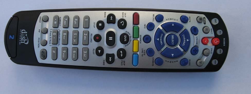
QVEFSK2LC
Nov 08, 2012Remote Control Device Transmitter
Equipment Class
DSC - Part 15 Security/Remote Control Transmitter
QVEFSRC01
Dec 01, 2011Scoop pointer remote and wireless presenter
Equipment Class
DXX - Part 15 Low Power Communication Device Transmitter
QVEFSRX01
Dec 01, 2011USB receiver for Scoop pointer remote and Scoop wireless presenter
Equipment Class
DXX - Part 15 Low Power Communication Device Transmitter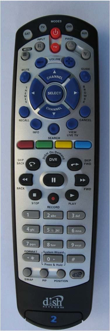
QVEFSK4U2
Aug 29, 2011Remote Control
Equipment Class
DXX - Part 15 Low Power Communication Device Transmitter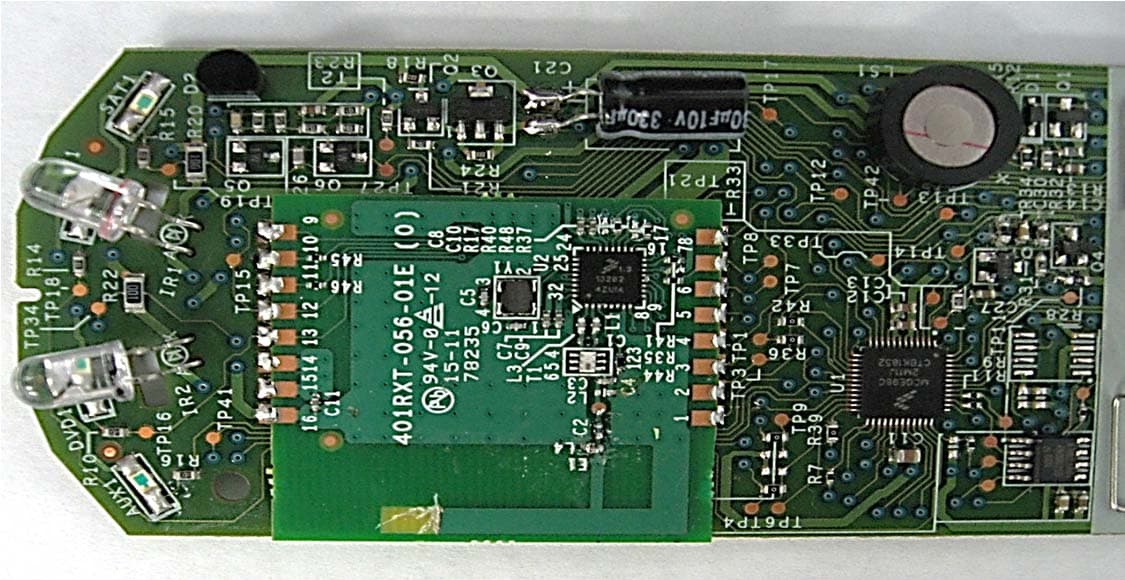
QVE4XIPR
Aug 10, 2011Remote Control
Equipment Class
DXX - Part 15 Low Power Communication Device Transmitter