QVEFSK4UFSK module
SMK Manufacturing, Inc.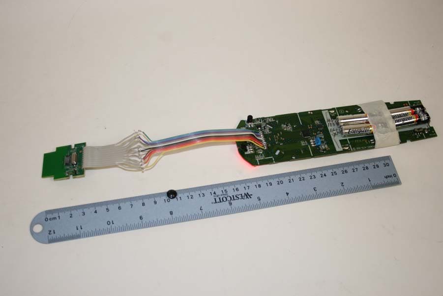
Click to zoom
Application Details
- Equipment Class
- DXX - Part 15 Low Power Communication Device Transmitter
- Date of Grant
- Jan 31, 2011
- Application Purpose
- Original Equipment
- Date of Application
- Jan 31, 2011
- Equipment Note
- FSK module
- Frequency Range
- 369.50000000 - 395.90000000
- Company
- SMK Manufacturing, Inc.
- Country
- United States
Documents & Files
Document Text
Text extracted from the exhibit documents filed with the FCC. Open a document above to read the original.
Users Manual
Installation Instructions PAGE: 1 OF 6 1055 Tierra Del Rey Chula Vista, CA91910 DATE: 12/21/10 H:\lgateno\Customer\EchoStar\FSK_Module\Silabs\FCC\Rev_4\Installation_Instructions_1_20_11.doc REVISIONS REV DESCRIPTION CHECK ENG DATE 1.0 Release Leon Gateno 12/10/10 2.0 Add Testing of the module once inside the remote Leon Gateno 1/20/11 REMARKS: Installation Instructions PAGE: 2 OF 6 1055 Tierra Del Rey Chula Vista, CA91910 DATE: 12/21/10 H:\lgateno\Customer\EchoStar\FSK_Module\Silabs\FCC\Rev_4\Installation_Instructions_1_20_11.doc INDEX 1 INTRODUCTION .......................................................................................................................................... 3 2 BLOCK DIAGRAM ....................................................................................................................................... 3 3 PICTURES...................................................................................................................................................... 4 4 STATEMENT................................................................................................................................................. 5 Installation Instructions PAGE: 3 OF 6 1055 Tierra Del Rey Chula Vista, CA91910 DATE: 12/21/10 H:\lgateno\Customer\EchoStar\FSK_Module\Silabs\FCC\Rev_4\Installation_Instructions_1_20_11.doc 1 INTRODUCTION This document describes the installation of the module into a remote. 2 BLOCK DIAGRAM The following is a Block Diagram for the remote: Linear Regulator 3.0Volts Vdd in Enable Block Digram FSK Module LG 12/7/10 The block diagram has two sections the BB and the RF. This device is been controlled by the remote control. The BB consists of a small ASIC that is used to set up registers and control words. These are used for timing purposes. The BB shares the same reference as the RF, which is a 10MHz crystal. Installation Instructions PAGE: 4 OF 6 1055 Tierra Del Rey Chula Vista, CA91910 DATE: 12/21/10 H:\lgateno\Customer\EchoStar\FSK_Module\Silabs\FCC\Rev_4\Installation_Instructions_1_20_11.doc The RF section consist of the transmitter in the RFIC, the exception of the 10 MHz crystal , internal matching networks , external filter and antenna. The module also has a linear regulator with an output of 3 volts. 3 PICTURES The following pictures describe the Module in terms of its components. Installation Instructions PAGE: 5 OF 6 1055 Tierra Del Rey Chula Vista, CA91910 DATE: 12/21/10 H:\lgateno\Customer\EchoStar\FSK_Module\Silabs\FCC\Rev_4\Installation_Instructions_1_20_11.doc The mother board and the module are connected via the flat ribbon cable. Steps for the installation of the remote: a) Connect the pin one of the Remote connector to the pin one of the module. The connection is done via a flat ribbon cable. b) Bend the cable in order for the cable to fit in the remote c) Install the module between the bottom Plastics and the remote. d) The side with the ribbon cable should be facing towards the remote . The antenna side should face away from the remote. e) Once nit is inside the remote test the remote to make sure the module is working properly. 4 STATEMENT Please make sure that the following statement is part of your owners manual: INFORMATION TO USER This device complies with Part 15 of the FCC Rules. Operation is subject to the following two conditions: (1) This device may not cause harmful interference, and (2) This device must accept any interference received, including interference that may cause undesired operation. This equipment has been tested and found to comply with the limits for Class B Digital Device, pursuant to Part 15 of the FCC Rules. These limits are designed to provide reasonable protection against harmful interference in a residential installation. This equipment generates and can radiate radio frequency energy and, if not installed and used in accordance with the instructions, may cause Installation Instructions PAGE: 6 OF 6 1055 Tierra Del Rey Chula Vista, CA91910 DATE: 12/21/10 H:\lgateno\Customer\EchoStar\FSK_Module\Silabs\FCC\Rev_4\Installation_Instructions_1_20_11.doc harmful interference to radio communications. However, there is no guarantee that interference will not occur in a particular installation. If this equipment does cause harmful interference to radio or television reception, which can be determined by turning the equipment off and on, the user is encouraged to try to correct the interference by one or more of the following measures. • Reorient or relocate the receiving antenna • Increase the separation between the equipment and receiver • Connect the equipment into an outlet on a circuit different from that to which the receiver is connected • Consult the dealer or an experienced radio/TV technician for help Any changes or modifications not expressly approved by the party responsible for compliance could void the user’s authority to operate the equipment. This device complies with Industry Canada license-exempt RSS standard(s). Operation is subject to the following two conditions: (1) this device may not cause interference, and (2) this device must accept any interference, including interference that may cause undesired operation of the device. Le présent appareil est conforme aux CNR d'Industrie Canada applicables aux appareils radio exempts de licence. L'exploitation est autorisée aux deux conditions suivantes : (1) l'appareil ne doit pas produire de brouillage, et (2) l'utilisateur de l'appareil doit accepter tout brouillage radioélectrique subi, même si le brouillage est susceptible d'en compromettre le fonctionnement. Label the final product with: Contains: FCC ID: QVEFSK4U IC: 3683B-FSK4U
Cover Letter(s)
1/19/2010 Nemko Canada Inc 303 River Road Ottawa, Ontario, Canada K1V 1H2 Attn: Director of Certification FCC ID: QVEFSK4U Authority to Act as Agent On our behalf, I appoint Alan Laudani of Nemko USA Inc., 11696 Sorrento Valley Rd, San Diego, CA, USA to act as our agent in the preparation of this application for equipment certification. I certify that submitted documents properly describe the device or system for which equipment certification is sought. I also certify that each unit manufactured, imported or marketed, as defined in Federal Communication Commission’s regulations will have affixed to it a label identical to that submitted for approval with this application. For instances where our authorized agent signs the application for certification on our behalf, I acknowledge that all responsibility for complying with the terms and conditions for certification, as specified by Nemko Canada Inc, still resides with SMK USA, 1055 Tierra Del Rey, Suite H, Chula Vista, CA 91910, USA. Agency agreement expiration date: June 1, 2011
Cover Letter(s)
Date : 1/21/11 Nemko Canada Inc. 303 River Road Ottawa, Ontario, Canada K1V 1H2 Attn: Director of Certification FCC ID: QVEFSK4U IC: 3683B-FSK4U Model: RXT9200-0505E Request Limited Modular Authority We hereby request Limited Modular Approval based on the numbered requirements identified below as we address them to be included in our application for equipment authorization. 1. The modular transmitter must have its own RF shielding. This is intended to ensure that the module does not have to rely upon the shielding provided by the device into which it is installed in order for all modular transmitter emissions to comply with Part 15 limits. It is also intended to prevent coupling between the RF circuitry of the module and any wires or circuits in the device into which the module is installed. Such coupling may result in non-compliant operation. The unit has no shielding. This is an exception to the rules for Modular Approval. The unit was tested alone and meets the emission standard. The unit will be installed inside remote controls. There will be the module and a motherboard. The motherboard and the PCB will have a ground layer separation. 2. The modular transmitter must have buffered modulation/data inputs (if such inputs are provided) to ensure that the module will comply with Part 15 requirements under conditions of excessive data rates or over-modulation. The data rate for all the interface signals are fixed data rate. Also, the incoming data is buffered by buffers and a layer of logic circuits. The data does not go directly to the modulator. 3. The modular transmitter must have its own power supply regulation. This is intended to ensure that the module will comply with Part 15 requirements regardless of the design of the power supplying circuitry in the device into which the module is installed. The module has its own regulator and input-output filters. Hence it’s independent of the input regulator. 4. The modular transmitter must comply with the antenna requirements of Section 15.203 and 15.204(c). The antenna must either be permanently attached or employ a “unique” antenna coupler (at all connections between the module and the antenna, including the cable). Any antenna used with the module must be approved with the module, either at the time of initial authorization or through a Class II permissive change. The “professional installation” provision of Section 15.203 may not be applied to modules. The antenna is a trace antenna that is a part of the PCB. Customer does not have access to the antenna and the antenna does not have a connector 5. The modular transmitter must be tested in a stand-alone configuration, i.e., the module must not be inside another device during testing. This is intended to demonstrate that the module is capable of complying with Part 15 emission limits regardless of the device into which it is eventually installed. Unless the transmitter module will be battery powered, it must comply with the AC line conducted requirements found in Section 15.207. AC or DC power lines and data input/output lines connected to the module must not contain ferrites, unless they will be marketed with the module (see Section 15.27(a)). The length of these lines shall be length typical of actual use or, if that length is unknown, at least 10 centimeters to insure that there is no coupling between the case of the module and supporting equipment. Any accessories, peripherals, or support equipment connected to the module during testing shall be unmodified or commercially available (see Section 15.31(i)). The module was tested in a stand alone method as requested. The unit is only battery powered and was tested with batteries. 6. The modular transmitter must be labeled with its own FCC ID number, and, if the FCC ID is not visible when the module is installed inside another device, then the outside of the device into which the module is installed must also display a label referring to the enclosed module. This exterior label can use wording such as the following: “Contains Transmitter Module FCC ID: XYZMODEL1” or “Contains FCC ID: XYZMODEL1.” Any similar wording that expresses the same meaning may be used. The Grantee may either provide such a label, an example of which must be included in the application for equipment authorization, or, must provide adequate instructions along with the module which explain this requirement. In the latter case, a copy of these instructions must be included in the application for equipment authorization. The Label document shows that the module will be labelled with the FCC ID etc. An instruction is provided to the manufacturer of the final products to add the external label. Please see the Installation Instruction documentation. 7. The modular transmitter must comply with any specific rule or operating requirements applicable to the transmitter and the manufacturer must provide adequate instructions along with the module to explain any such requirements. A copy of these instructions must be included in the application for equipment authorization. For example, there are very strict operational and timing requirements that must be met before a transmitter is authorized for operation under Section 15.231. For instance, data transmission is prohibited, except for operation under Section 15.231(e), in which case there are separate field strength level and timing requirements. Compliance with these requirements must be assured. Once the data is in the module the timing inside the module is done via internal logic inside of the IC. Hence, the IC itself controls the transmission of the signal. This is done with the help of logic circuits. The test report shows compliance with 15.231(a). 8. The modular transmitter must comply with any applicable RF exposure requirements. For example, FCC Rules in Sections 2.1091, 2.1093 and specific Sections of Part 15, including 15.319(i), 15.407(f), 15.253(f) and 15.255(g), require that Unlicensed PCS, UNII and millimeter wave…
Text truncated - open the document above for the full version.
Cover Letter(s)
12/28/2011 Nemko Canada Inc 303 River Road Ottawa, Ontario, Canada K1V 1H2 Attn: Director of Certification FCC ID: QVEFSK4U IC: 3683B-FSK4U Request for Confidentiality Pursuant to Sections 0.457 and 0.459 of the Commissions rules, we hereby request that the following documents be held confidential: • Schematics • Block diagram • BOM • Operation Description The Applicant understands that pursuant to Rule 0.457(d)(I)(ii), disclosure of this Application and all accompanying documentation will not be made before the date of the Grant for this Application.
External Photos
Ribbon cable extended for Modular Approval requirement of > 10cm
ID Label/Location Info
RXT9200-0505E FCC ID: QVEFSK4U IC: 3683B-FSK4U
Internal Photos
Ribbon cable extended for Modular Approval requirement of > 10cm
Test Report
Nemko USA, Inc. 11696 Sorrento Valley Rd., Suite F San Diego, CA 92121-1024 Phone (858) 755-5525 Fax (858) 452-1810 FCC Part 15 Subpart C, 15.231: 31/01/2011 Certification Test Report In Accordance With: FCC Part 15 Subpart C, 15.231 RSS-210 Issue 8 December 2010 Applicant: SMK Manufacturing, Inc 1055 Tierra Del Rey Chula Vista, CA 91910 Equipment Under Test (EUT): FSK Module Model: RXT9200-0505E FCC ID: QVEFSK4U IC: 3683B-FSK4U Tested By: Nemko USA Inc. 11696 Sorrento Valley Road, Suite F San Diego, CA 92121 Test Report Number: 2010 12163444 FCC Date: January 25, 2011 Project Number 43834 NEX Number 149167 Total Number of Pages: 26 Nemko USA, Inc. 11696 Sorrento Valley Road, Suite F, San Diego, CA 92121 Phone (858) 755-5525 Fax (858) 452-1810 Report Number: 2010 12163444 FCC FCC ID: QVEFSK4U IC: 3683B-FSK4U Specification: FCC Part 15 Subpart C, 15.231 RSS-210 Issue 8 December 2010 Page 2 of 26 Section 1. Summary of Test Results 1.1 General All measurements are traceable to national standards These tests were conducted on a sample of the equipment for the purpose of demonstrating compliance with Part 15; Subpart C. Radiated tests were conducted is accordance with ANSI C63.4-2003. Radiated emissions are made on an open area test site. A description of the test facility is on file with the FCC. The assessment summary is as follows: Apparatus Assessed: FSK Module Model: RXT9200-0505E Specification: FCC Part 15 Subpart C, 15.231 RSS-210 Issue 8 December 2010 Date Received in Laboratory: December 17, 2010 Compliance Status: Complies Exclusions: None Non-compliances: None Nemko USA, Inc. 11696 Sorrento Valley Road, Suite F, San Diego, CA 92121 Phone (858) 755-5525 Fax (858) 452-1810 Report Number: 2010 12163444 FCC FCC ID: QVEFSK4U IC: 3683B-FSK4U Specification: FCC Part 15 Subpart C, 15.231 RSS-210 Issue 8 December 2010 Page 3 of 26 1.2 Report Release History REVISION DATE COMMENTS - January 25, 2011 Prepared By: Alan Laudani - January 25, 2011 Initial Release: Alan Laudani Note that the results contained in this report relate only to the items tested and were obtained in the period between the date of initial receipt of samples and the date of issue of the report. This test report has been completed in accordance with the requirements of ISO/IEC 17025. Nemko USA Inc. authorizes the applicant to reproduce this report provided it is reproduced in its entirety and for use by the company’s employees only. Any use which a third party makes of this report, or any reliance on or decisions to be made based on it, are the responsibility of such third parties. Nemko USA Inc. accepts no responsibility for damages, if any, suffered by any third party as a result of decisions made or actions based on this report. Alan Laudani, RF/EMC Test Engineer Nemko USA, Inc. 11696 Sorrento Valley Road, Suite F, San Diego, CA 92121 Phone (858) 755-5525 Fax (858) 452-1810 Report Number: 2010 12163444 FCC FCC ID: QVEFSK4U IC: 3683B-FSK4U Specification: FCC Part 15 Subpart C, 15.231 RSS-210 Issue 8 December 2010 Page 4 of 26 TABLE OF CONTENTS Section 1. Summary of Test Results.......................................................................... 2 1.1 General................................................................................................................. 2 1.2 Report Release History ........................................................................................ 3 Section 2: Equipment Under Test ................................................................................... 5 2.1 Theory of Operation.............................................................................................. 5 2.2 Technical Specifications of the EUT ..................................................................... 5 Section 3: Test Conditions .............................................................................................. 6 3.1 Specifications ....................................................................................................... 6 3.2 Deviations From Laboratory Test Procedures...................................................... 6 3.3 Test Environment ................................................................................................. 6 3.4 Test Equipment .................................................................................................... 6 Section 4: Observations .................................................................................................. 7 4.1 Modifications Performed During Assessment....................................................... 7 4.2 Record Of Technical Judgements ........................................................................ 7 4.3 EUT Parameters Affecting Compliance ................................................................ 7 4.4 Tests Deleted ....................................................................................................... 7 4.5 Additional Observations........................................................................................ 7 Section 5: Results Summary ........................................................................................... 8 5.1 Test Results.......................................................................................................... 8 Appendix A: Test Results ................................................................................................ 1 Conducted Emissions...................................................................................................... 1 Occupied Bandwidth....................................................................................................... 2 Frequency Stability.......................................................................................................... 6 Types of Momentary Signals ........................................................................................... 7 Duty Cycle ....................................................................…
Text truncated - open the document above for the full version.
Contact Information
Applicant
Tom Fukushima(Engineering Manager)
Technical Contact
SMK Manufacturing, IncLeon W Gateno
[email protected]619-216-6425
1055 Tierra Del Rey Suite H · Chula Vista · United States
Non-Technical Contact
SMK Manufacturing, IncLeon W Gateno
[email protected]619-216-6425
Test Firm
Nemko USA, Inc. - San Diego EMC DivisionJan Blomgren
[email protected]760-444-3500
Technical Specifications
| # | Rule Parts | Frequency Range | Power Output |
|---|---|---|---|
| 1 | 15C | 369.5 MHz - 395.9 MHz | - |
Other Applications from SMK Manufacturing, Inc.
QVE4SYDN
Mar 31, 2015Remote Control with 2.4GHz ISM radio for a set top box
Equipment Class
DTS - Digital Transmission System
QVEFSK2LC
Nov 08, 2012Remote Control Device Transmitter
Equipment Class
DSC - Part 15 Security/Remote Control Transmitter
QVEFSRC01
Dec 01, 2011Scoop pointer remote and wireless presenter
Equipment Class
DXX - Part 15 Low Power Communication Device Transmitter
QVEFSRX01
Dec 01, 2011USB receiver for Scoop pointer remote and Scoop wireless presenter
Equipment Class
DXX - Part 15 Low Power Communication Device Transmitter
QVEFSK4U2
Aug 29, 2011Remote Control
Equipment Class
DXX - Part 15 Low Power Communication Device Transmitter