QY4AVT9003A900 MHz Audio/Video Transmitter
Applied Wireless, Inc.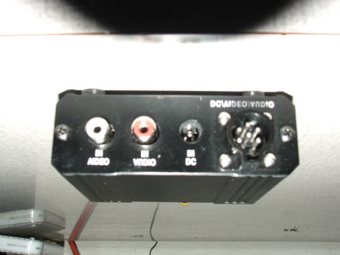
Click to zoom
Application Details
- Equipment Class
- DXX - Part 15 Low Power Communication Device Transmitter
- Date of Grant
- Jan 04, 2007
- Application Purpose
- Original Equipment
- Date of Application
- Jan 04, 2007
- Equipment Note
- 900 MHz Audio/Video Transmitter
- Frequency Range
- 907.00000000 - 923.00000000
- Company
- Applied Wireless, Inc.
- Country
- United States
Documents & Files
Document Text
Text extracted from the exhibit documents filed with the FCC. Open a document above to read the original.
Users Manual
Long Range Wireless Applications USER’S MANUAL 900 MHz Audio / Video Transmitter Model No. AVT900-3A Product Description Model AVT900-3A from Applied Wireless, Inc. is a high quality transmitter designed to broadcast standard NTSC or PAL video signals, along with line-level audio signals, to an appropriate receiver (such as Applied Wireless Inc.’s model AVR900-3). Conforming to FCC Part 15 requirements for unlicensed use, Model AVT900-3A will transmit over distances up to 750 feet.* The range may be increased substantially through the use of a directional antenna (such as a flat panel or yagi) at the receiver. The AVT900-3A transmitter provides three user-selectable channels of operation to enable simultaneous operation of multiple transmitters in a common area. The transmitter incorporates precise FM modulation and sophisticated filters to ensure stable, interference-free high quality color or B/W video plus audio reception. The AVT900-3A transmitter is housed in a small yet rugged aluminum extrusion enclosure (dimensions: 3.25”W x 2.5”L). An AC power converter (12VDC) is supplied, along with RCA phono-type video and audio cables, as well as a combination multi- conductor power/audio/video cable assembly, for connection to video and audio sources. The AVT900-3A transmitter is well-suited for many diverse applications, including distribution of AV entertainment content throughout a building, commercial and industrial surveillance, monitoring, security, access control, etc. Using the AVT900-3A in Non-Stationary Applications If the AVT900-3A is to be used in an application in which it will be moving while broadcasting (such as with a hand-held video camera, for example), it is strongly suggested that the Applied Wireless Diversity Receiver (model DAV900-3) be utilized. This advanced multi-antenna receiver will minimize the effects of multipath interference to provide more stable video images and audio reproduction. The improvement in performance is especially noticeable when the distance between the transmitter and receiver is extended and/or obstructions exist between them. * Unobstructed, straight line-of-sight range, when used with the transmitter’s standard quarter-wave antenna (included). Table 1 Specifications Operating Frequency Channel 1 907 MHz Channel 2 915 MHz Channel 3 923 MHz RF Output Power 1 mW (0 dBm) Operating Voltage 7.5 to 18VDC Operating Current 65 mA Video Frequency Response 0.5 – 5.0 MHz Signal to Noise Ratio 60 dB FM Deviation (@ 1V P-P input)+/- 3 MHz Differential Gain Error 3% p-p (max) Differential Phase Error 3% p-p (max) Harmonic Suppression -45 dBc Antenna Output Impedance 50 Ohms Operating Temperature Range -20°C to +70°C Storage Temperature Range -50°C to +150°C Installation Instructions Before Beginning the Installation Plan the installation of the AVT900-3A transmitter carefully. The physical location and orientation of the unit itself will have a significant influence on reception quality at the receiver, particularly at longest ranges. The unit, and its standard antenna, should be positioned vertically (pointing either up or down). If necessary, use double-sided foam tape or hook & loop fasteners (not supplied) to secure the unit to a vertical surface. Also, keep in mind that the RF signal from the transmitter will travel through most non-metallic building materials (wood, stucco, brick, etc.), however maximum stated reception range is based on unobstructed line of sight conditions. Selecting the Channel of Operation Referring to Figure 1, use a small flat-blade screwdriver to select the channel (frequency) on which the transmitter will broadcast, by aligning the triangle-shaped pointer (not the screwdriver slot) to the number of the desired channel. Be sure to set the receiver to the matching channel. Channels are as follows: Channel 1: 907 MHz Channel 2: 915 MHz Channel 3: 923 MHz Any other setting of the channel selector (0, 4, 5, 6, 7, 8, 9) defaults to Channel 1. If two AVT900-3A transmitters are to be used simultaneously in a common area (so as to broadcast two different audio & video sources), set one unit to Channel 1 and the other unit to Channel 3. It is not advisable to attempt to use three units simultaneously. Connecting Audio and Video to the AVT900-3A Following the guidelines below, connect line level audio and video sources (outputs from a DVD player, for example) to the corresponding line-level input jacks on the transmitter’s rear panel (refer to Figure 2). Audio – If a microphone is to be used as the audio source, an external microphone preamp (not supplied) must be used to raise the microphone’s output signal to the required line level. Video – The AVT900-3A’s video input presents a terminated 75-ohm load to the output of the video source device. Accordingly, no other device(s) besides the AVT900-3A should be connected to the video source. If any additional device(s) must be driven by the source device, a video distribution amplifier (not supplied) must be used. Connecting Power to the AVT900-3A The AVT900-3A requires an external power source of between 7.5 and 18 volts DC. A plug-in power converter (12VDC) is supplied with the AVT900-3A. If preferred, a battery (not supplied) may be used instead of the power converter. A 9volt alkaline battery will operate the transmitter continuously for several hours. Figure 1 - Front Panel Figure 2 – Rear Panel CAUTION: Do NOT apply power to the AVT900-3A unless the supplied antenna is attached to its mating jack on the front panel. Powering the transmitter without an antenna may result in failure of the transmitter’s RF output device and void the warranty. To use the supplied power converter, insert its 2.1mm plug into the DC IN jack on the transmitter’s rear panel (refer to Figure 2). Plug the converter into a live 120VAC outlet. The transmitter’s red Power indicator LED (on the front panel, refer to Figure 1) should illuminate. To connect a battery, refer to Figure 3 and Table 2. Using the Combi…
Text truncated - open the document above for the full version.
Cover Letter(s)
Scott McCutchan From: Scott McCutchan [[email protected]] Sent: Thursday, January 04, 2007 9:16 AM To: '[email protected]'; 'Ruby' Subject: FCC ID: QY4AVT9003A 1/5/2007 Mr. Ramirez: In order for processing of this certification application (FCC ID: QY4AVT9003A) to continue, the following issue(s) will have to be addressed: 1) The application form indicates a frequency range of 902-928 MHz; however, the test report indicates that the device operates from 907-923 MHz. Please correct the application form. 2) Please indicate the procedure used for making average measurements. 3) The device has two sets of input ports; composite video/audio ports, and a DC/Video/Audio port. The test report seems to indicate that only the composite input mode was tested. Were both modes tested? 4) Please indicate the connector-type for the antenna. The item(s) indicated above must be submitted before processing can continue on the above referenced application. Failure to provide the requested information within 60 days of the original e-mail date may result in application dismissal and forfeiture of the filing fee. Also, please note that partial responses increase processing time and should not be submitted. Please upload responses and/or exhibits to the electronic filing website. Your correspondence number is QY4AVT9003A-1. Best regards, Scott McCutchan Operations Manager Compatible Electronics TCB
Cover Letter(s)
Correspondence by Project Project Number: Correspondence NumberMemo QY4AVT9003A-1 1) Changes were made to the application to indicate correct frequency range. 2) Video Average procedure was used to take average measurements. 3) Yes. Both modes were tested. 4) Connector type of the antenna used was SMA. Correspondence NumberMemo QY4AVT9003A-1 Mr. McCutchan, In response to your e-mail, I am addressing each issue in the order received. 1) The form 731 was modified to correct the frequency range as requested. 2) The averaging procedure is included in the report in section 7.1.5 3) The description of the configurations tested is also in the report section 4.1. 4) The antenna connector is a reverse polarity SMA connector. Please see the newly uploaded report A61205F1. Best Regards, Ruby A. Hall -177483602
External Photos
EXTERNAL PHOTOS FCC ID: QY4AVT9003A TOP VIEW FCC ID: QY4AVT9003A BOTTOM VIEW FCC ID: QY4AVT9003A FRONT OF EUT FCC ID: QY4AVT9003A FRONT OF EUT COVER OFF FCC ID: QY4AVT9003A BACK OF EUT WITH ANTENNA FCC ID: QY4AVT9003A TOP VIEW ANTENNA REMOVED
ID Label/Location Info
Long Range Wireless Applications Applied Wireless, Inc. ● 1250 Avenida Acaso, Suite F ● Camarillo, CA 93012 Phone (805) 383-9600 ● Fax (805) 383-9001 email: [email protected] ● www.appliedwireless.com 900 MHz Audio/Video Transmitter Model AVT900-3A FCC Identifier Label Placement (bottom view) APPLIED WIRELESS, INC. Camarillo, CA FCC ID: QY4AVT9003A This device complies with Part 15 of the FCC Rules. Operation is subject to the following two conditions: (1) This device may not cause harmful interference and (2) This device must accept any interference received, including interference that may cause undesired operation.
Internal Photos
INTERNAL PHOTOS FCC ID: QY4AVT9003A INTERNAL TOP VIEW FCC ID: QY4AVT9003A INTERNAL TOP WITH RF COVER REMOVED FCC ID: QY4AVT9003A INTERNAL TOP VIEW WITH INTERNAL RF COVER FCC ID: QY4AVT9003A INTERNAL BOTTOM OF BOARD FCC ID: QY4AVT9003A INTERNAL BOTTOM OF BOARD WITH ANTENNA INSTALLED
Test Report
FCC ID: QY4AVT9003A Report Number: A61205F1 2337 TROUTDALE DRIVE, AGOURA, CALIFORNIA, 91301 • PH: (818) 597-0600 FX: (818) 597-1187 Page 1 of 17 FCC PART 15, SUBPART C TEST REPORT for AUDIO/VIDEO TRANSMITTER Model: AVT900-3 FCC ID: QY4AVT9003A Prepared for APPLIED WIRELESS, INC. 1250 AVENIDA ACASO, UNIT F CAMARILLO, CA 93012 Prepared by: _____________________ REYNALD O. RAMIREZ Approved by: ____________________ RUBY A. HALL COMPATIBLE ELECTRONICS INC. 2337 TROUTDALE DRIVE AGOURA, CALIFORNIA 91301 (818) 597-0600 DATE: DECEMBER 12, 2006 REPORT APPENDICES TOTAL BODY A B C D E PAGES 17 2 2 2 13 19 55 This report shall not be reproduced except in full, without the written approval of Compatible Electronics. FCC ID: QY4AVT9003A Report Number: A61205F1 2337 TROUTDALE DRIVE, AGOURA, CALIFORNIA, 91301 • PH: (818) 597-0600 FX: (818) 597-1187 Page 2 of 17 TABLE OF CONTENTS Section / Title PAGE GENERAL REPORT SUMMARY 4 SUMMARY OF TEST RESULTS 4 1. PURPOSE 5 2. ADMINISTRATIVE DATA 6 2.1 Location of Testing 6 2.2 Traceability Statement 6 2.3 Cognizant Personnel 6 2.4 Date Test Sample was Received 6 2.5 Disposition of the Test Sample 6 2.6 Abbreviations and Acronyms 6 3. APPLICABLE DOCUMENTS 7 4. DESCRIPTION OF TEST CONFIGURATION 8 4.1 Description of Test Configuration - EMI 8 4.1.1 Photograph of Test Configuration – EMI 8 4.1.1 Cable Construction and Termination 9 5. LISTS OF EUT, ACCESSORIES AND TEST EQUIPMENT 10 5.1 EUT and Accessory List 10 5.2 EMI Test Equipment 11 6. TEST SITE DESCRIPTION 12 6.1 Test Facility Description 12 6.2 EUT Mounting, Bonding and Grounding 12 7. TEST PROCEDURES 13 7.1 RF Emissions 13 7.1.1 Conducted Emissions Test 13 7.1.2 Radiated Emissions Test 14 7.1.3 RF Emissions Test Results 15 7.1.4 Sample Calculations 16 7.1.5 Video Averaging 16 8. TEST PROCEDURE DEVIATIONS 17 9. CONCLUSIONS 17 FCC ID: QY4AVT9003A Report Number: A61205F1 2337 TROUTDALE DRIVE, AGOURA, CALIFORNIA, 91301 • PH: (818) 597-0600 FX: (818) 597-1187 Page 3 of 17 LIST OF APPENDICES APPENDIX TITLE A Laboratory Accreditations B Modifications to the EUT C Additional Models Covered Under This Report D Diagrams, Charts and Photos • Test Setup Diagrams • Antenna and Preamplifier Gain Factors • Radiated and Conducted Emissions Photos E Data Sheets LIST OF FIGURES FIGURE TITLE 1 Conducted Test Setup 2 Plot Map And Layout of Test Site FCC ID: QY4AVT9003A Report Number: A61205F1 2337 TROUTDALE DRIVE, AGOURA, CALIFORNIA, 91301 • PH: (818) 597-0600 FX: (818) 597-1187 Page 4 of 17 GENERAL REPORT SUMMARY This electromagnetic emission report is generated by Compatible Electronics Inc., which is an independent testing and consulting firm. The test report is based on testing performed by Compatible Electronics personnel according to the measurement procedures described in the test specifications given below and in the "Test Procedures" section of this report. The measurement data and conclusions appearing herein relate only to the sample tested and this report may not be reproduced in any form except in full, without the written permission of Compatible Electronics. This report must not be used to claim product endorsement by NVLAP or any other agency of the U.S. Government. Device Tested: Audio/Video Transmitter Model: AVT900-3 S/N: None Product Description: This is a “900 MHz” Audio/Video Transmitter designed to broadcast standard NTSC or PAL video signals and line level audio signals to an appropriate receiver over distances up to 750 feet. Modifications: The EUT was not modified during the testing. Manufacturer: Applied Wireless, Inc. 1250 Avenida Acaso, Unit F Camarillo, CA 93012 Test Dates: Dec. 4 & 5, 2006 Test Specifications: EMI requirements FCC CFR Title 47, Part 15 Subpart C Test Procedure: ANSI C63.4: 2003. SUMMARY OF TEST RESULTS TEST DESCRIPTION RESULTS 1 Radiated RF Emissions, 9 kHz to 9230 MHz Complies with the limits of FCC CFR Title 47, Part 15 Subpart C 15.205, 15.209 & 15.249, and the requirements of 15.31(e). 2 Conducted Emissions 150 KHz to 30 MHz Complies with the limits of FCC CFR Title 47, Part 15 Subpart C 15.207. FCC ID: QY4AVT9003A Report Number: A61205F1 2337 TROUTDALE DRIVE, AGOURA, CALIFORNIA, 91301 • PH: (818) 597-0600 FX: (818) 597-1187 Page 5 of 17 1. PURPOSE This document is a qualification test report based on the Electromagnetic Interference (EMI) tests performed on the Audio/Video Transmitter Model: AVT900-3. The EMI measurements were performed according to the measurement procedure described in ANSI C63.4: 2003. The tests were performed in order to determine whether the electromagnetic emissions from the equipment under test, referred to as EUT hereafter, are within the specification limits and requirements defined in FCC CFR Title 47, Part 15 Subpart A (15.31e), Subpart B and Subpart C (15.205, 15.209 and 15.249). FCC ID: QY4AVT9003A Report Number: A61205F1 2337 TROUTDALE DRIVE, AGOURA, CALIFORNIA, 91301 • PH: (818) 597-0600 FX: (818) 597-1187 Page 6 of 17 2. ADMINISTRATIVE DATA 2.1 Location of Testing The EMI tests described herein were performed at the test facility of Compatible Electronics, 2337 Troutdale Drive, Agoura, California 91301. 2.2 Traceability Statement The calibration certificates of all test equipment used during the test are on file at the location of the test. The calibration is traceable to the National Institute of Standards and Technology (NIST). 2.3 Cognizant Personnel Applied Wireless, Inc. Lee Fleishman Director of Marketing Mark Simon V. P. of Engineering Compatible Electronics Inc. Reynald O. Ramirez Sr. Test Engineer Andre D. Khan Test Technician Ruby A. Hall Lab Manager 2.4 Date Test Sample was Received The test sample was received on Dec. 4, 2006. 2.5 Disposition of the Test Sample The test sample remains at Compatible Electronics, Inc. 2.6 Abbreviations and Acronyms The following abbreviations and acronyms may be used in this document. RF Radio Frequency EMI Electromagnetic Interference EUT Equipment Under Test P/N Part Number S/N Serial Number HP Hewlett…
Text truncated - open the document above for the full version.
Test Setup Photos
TEST SETUP PHOTOS FCC ID: QY4AVT9003A FRONT VIEW RADIATED FCC ID: QY4AVT9003A REAR VIEW RADIATED FCC ID: QY4AVT9003A FRONT VIEW CONDUCTED FCC ID: QY4AVT9003A REAR VIEW CONDUCTED
Contact Information
Applicant
David Nichols(President)
Technical Contact
Compatible ElectronicsReynald O. Ramirez
[email protected]818-597-0600
2337 Troutdale Drive · Agoura, California · United States
Test Firm
Compatible ElectronicsRuby Hall
Technical Specifications
| # | Rule Parts | Frequency Range | Power Output |
|---|---|---|---|
| 1 | 15C | 907 MHz - 923 MHz | - |
Other Applications from Applied Wireless, Inc.
QY4KTXW303
Jan 11, 2015Remote Transmitter
Equipment Class
DSC - Part 15 Security/Remote Control Transmitter
QY4SP8MAIN
Jun 24, 2014True Bypass Analog Programmable Wireless Control System
Equipment Class
DXT - Part 15 Low Power Transceiver, Rx Verified
QY4265
Mar 07, 2007900 MHz Audio Transmitter Module
Equipment Class
DXX - Part 15 Low Power Communication Device Transmitter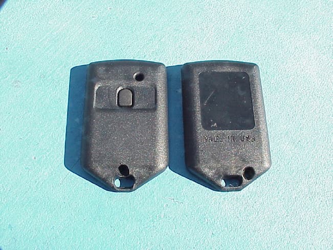
QY4KTX433
Jun 11, 2003Remote Control Transmitter
Equipment Class
DSC - Part 15 Security/Remote Control Transmitter