QY4KTXW303Remote Transmitter
Applied Wireless, Inc.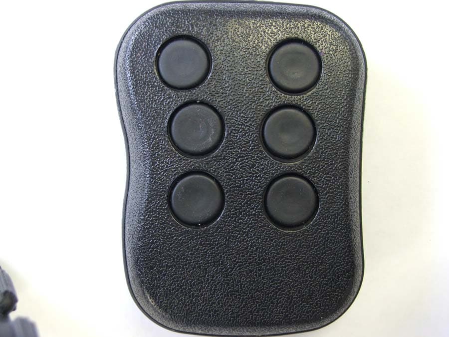
Click to zoom
Application Details
- Equipment Class
- DSC - Part 15 Security/Remote Control Transmitter
- Date of Grant
- Jan 11, 2015
- Application Purpose
- Original Equipment
- Date of Application
- Jan 11, 2015
- Equipment Note
- Remote Transmitter
- Frequency Range
- 303.80000000 - 303.80000000
- Company
- Applied Wireless, Inc.
- Country
- United States
Documents & Files
Document Text
Text extracted from the exhibit documents filed with the FCC. Open a document above to read the original.
Users Manual
1250 Avenida Acaso, Unit F, Camarillo, CA 93012 • Phone (805) 383-9600 • Fax (805) 383-9001 www.appliedwireless.com USER’S MANUAL RCR/KTXWxxx Remote Control System INTRODUCTION This product is used in miscellaneous applications requiring short-range remote control of on/off functions. INSTRUCTION TO THE USER FCC ID:QY4KTXW303 This device complies with Part 15 of the FCC Rules. Operation is subject to the following two conditions: (1) This device may not cause harmful interference and (2) This device must accept any interference received, including interference that may cause undesired operation. This unit has been tested and found to be in comply with the limits for a class B digital device, pursuant to part 15 of the FCC Rules. These limits are designed to provide reasonable protection against harmful interference in a residential installation. This equipment generates, uses and can radiate radio frequency energy and if not installed and used in accordance with the instructions, may cause harmful interference to radio communications. However, there is no guarantee that interference will not occur in a particular installation. If this equipment does cause harmful interference to radio or television reception, which can be determined by turning the equipment off and on, the user is encouraged to try to correct the interference by one or more of the following measures: • Reorient or relocate the receiving antenna • Increase the separation between the equipment and the receiver • Connect the equipment into an outlet on a circuit different from that which the receiver is connected. • Consult the dealer or an experienced radio/TV technician for help. The user is cautioned that changes and modifications made to the equipment without the approval of manufacturer could void the user’s authority to operate the equipment. OPERATION Transmission Range The transmission range of this unit depends upon the environment of the signal path, the type of receiver used and the type of receive antenna used. Using Applied Wireless RCR receiver and a quarter wave vertical antenna, line-of-sight range of 350 feet is normal. By using a dipole antenna (DP300 or DPA300A) will extend the range even further. Non line-of-site applications may have significantly shorter transmission range, depending upon the nature of the obstruction. Addressing For security purposes, this transmitter is programmed to one of over 16 million different addresses. The receiver must be programmed to the same address code as the transmitter. The receiver may come programmed to your transmitter from the factory. If not, you will need to have the receiver “learn” the transmitter ID. To program the receiver, remove the receiver antenna (to prevent the receiver from inadvertently learning an undesired transmitter), press and hold (for at least 5 seconds) the learn button on the receiver (until the learn LED lights), and then press and hold any button on the transmitter until the LEARN light goes out. The transmitter must be within two to 3 feet of he receiver. When the learn button goes out, the receiver has finished the programming. The receiver may learn up to 4 different transmitter codes. If a fifth transmitter is programmed, the first transmitter ID code that was programmed will be deleted and replaced with the new ID. If more than 4 transmitters need to be used with the receiver, please request the factory to set up the KTXW transmitters with the same ID codes. Modes of Operation Momentary, Latched or Toggle The RCR receiver comes from the factory in the MOMENTARY mode. In this mode, the relay output is activated for only as long as the keyfob button is pressed. The other two modes work as follows: Latched Mode A relay activates when its associated button on the remote is depressed, and remains active after the button is released. When a different button (also set up for latch mode) on the remote is pressed, the currently active relay (or output) will de-activate, and the relay corresponding to the button just pressed will activate. A typical application of buttons used in latch mode are to have separate ON and OFF buttons. Toggle Mode A relay activates when its associated button on the remote is depressed, and remains active after the button is released. A subsequent press of the same button on the remote will deactivate the relay. In this mode, each of the relays is completely independent of the others, thus any combination of one or more relays, or no relays, may be active at any given time. Mode Combinations Each relay may have different modes of operation. For instance, buttons one and two may be set up as latched for an on button and off button application, while buttons 3 and 4 may be set up as momentary. The 8 position DIP switch sets the mode for each relay as outlined in the table. Relay/B utto nSwitch - Center + 11To ggleM o mentaryLatched 22To ggleM o mentaryLatched 33To ggleM o mentaryLatched 44To ggleM o mentaryLatched 55To ggleM o mentaryLatched 66To ggleM o mentaryLatched 7no t usedno t usedno t used 8no t usedno t usedno t used 8 P o sitio n M o de Switch If LATCHED operation is used, it will be necessary to specify which buttons will be used in a Latch Group. Latch groups are used so that buttons set up as momentary or toggle don’t affect the operation of those buttons set up as latched. It also allows the setup of multiple latched pairs, for instance if you wanted to have on and off buttons for 3 sets of equipment independently. Only one relay within a Latch Group can be energized at any given time. Latched groups are set up using the 4-position DIP switch (see table). SwitchONOFFLATCH MODE Button Groups Button Groups Button Groups 1√H o riz x31,2 2, 33, 4 1√Vert x21, 3, 52, 4, 6 2√D ual1, 2, 33, 4, 5 3√Glo bal Unlat c h1, 2, 3, 4, 5, 6 4√M aster OffB utto n 6 turns o ff all relays, regardless o f mo de Latch Gro up Switch • Switch 1 shall provide the selection between horizontally-related button pairs or vertically-re…
Text truncated - open the document above for the full version.
External Photos
EUT TOP FCC ID: QY4KTXW303 EUT BOTTOM FCC ID: QY4KTXW303
Internal Photos
EUT COVER OFF FCC ID: QY4KTXW303 PCB TOP FCC ID: QY4KTXW303 PCB BOTTOM FCC ID: QY4KTXW303
RF Exposure Info
SAR Exclusion Justification This device FCC ID:is excluded from SAR testing by the following justification The maximum power that the transmitter is capable of is1.00mW Using the following formula from section 4.3.1 of KDB 447498at test separation distances ≤ 50 mm [(max. power of channel, including tune-up tolerance, mW) / (min. test separation distance, mm)] * [√f(GHz)] Duty Cycle 11.00% Value1-g (mW)10-g (mW) 0.11181589 "Value" is3, the SAR test exclusion threshold 1-g power limit10-g power limit 272680 “source-based” time-averaging based on an inherent property or duty-cycle of a device is allowed. An example of this is the determination of exposure from a device that uses digital technology such as a time-division multiple-access (TDMA) scheme for transmission < 50mm power limits for above caclulation using specified frequency QY4KTXW303 Max Peak Power (dBm)Min Separation distance (mm)Frequency (Ghz) When the minimum test separation distance is < 5 mm, a distance of 5 mm according to 5) in section 4.1 is applied to determine SAR test exclusion. 0.303850 SAREXJUST-B-0-43REV A01/21/2014
Test Report
FCC ID: QY4KTXW303 Report Number: A41121F1 2337 TROUTDALE DRIVE, AGOURA, CALIFORNIA, 91301 PH: (818) 597-0600 FX: (818) 597-1187 Page 1 of 19 FCC PART 15, SUBPART C TEST REPORT for REMOTE TRANSMITTER Model: KTXW303C FCC ID: QY4KTXW303 Prepared for APPLIED WIRELESS, INC. 1250 AVENIDA ACASO, UNIT F CAMARILLO, CA 93012 Prepared by: _____________________ REYNALD O. RAMIREZ Approved by: ____________________ RUBY A. HALL COMPATIBLE ELECTRONICS INC. 2337 TROUTDALE DRIVE AGOURA, CALIFORNIA 91301 (818) 597-0600 DATE: NOVEMBER 21, 2014 REPORT APPENDICES TOTAL BODY A B C D E PAGES 19 2 2 2 12 20 57 This report shall not be reproduced except in full, without the written approval of Compatible Electronics. FCC ID: QY4KTXW303 Report Number: A41121F1 2337 TROUTDALE DRIVE, AGOURA, CALIFORNIA, 91301 PH: (818) 597-0600 FX: (818) 597-1187 Page 2 of 19 TABLE OF CONTENTS Section / Title PAGE GENERAL REPORT SUMMARY 4 SUMMARY OF TEST RESULTS 4 1. PURPOSE 5 2. ADMINISTRATIVE DATA 6 2.1 Location of Testing 6 2.2 Traceability Statement 6 2.3 Cognizant Personnel 6 2.4 Date Test Sample was Received 6 2.5 Disposition of the Test Sample 6 2.6 Abbreviations and Acronyms 6 3. APPLICABLE DOCUMENTS 7 4. DESCRIPTION OF TEST CONFIGURATION 8 4.1 Description of Test Configuration - Emissions 8 4.1.1 Photograph of Test Configuration – Emissions 8 4.1.2 Cable Construction and Termination 9 5. LISTS OF EUT, ACCESSORIES AND TEST EQUIPMENT 10 5.1 EUT and Accessory List 10 5.2 Emissions Test Equipment 11 6. TEST SITE DESCRIPTION 12 6.1 Test Facility Description 12 6.2 EUT Mounting, Bonding and Grounding 12 7. TEST PROCEDURES 13 7.1 RF Emissions 13 7.1.1 Conducted Emissions Test 13 7.1.2 Radiated Emissions Test 14 7.1.3 Radiated Emissions Test (continued) 15 7.1.5 Bandwidth of the Fundamental 17 7.1.6 Sample Calculations 18 8. TEST PROCEDURE DEVIATIONS 19 9. CONCLUSIONS 19 FCC ID: QY4KTXW303 Report Number: A41121F1 2337 TROUTDALE DRIVE, AGOURA, CALIFORNIA, 91301 PH: (818) 597-0600 FX: (818) 597-1187 Page 3 of 19 LIST OF APPENDICES APPENDIX TITLE A Laboratory Accreditations B Modifications to the EUT C Additional Models Covered Under This Report D Diagrams, Charts and Photos Test Setup Diagrams Antenna and Preamplifier Gain Factors Radiated and Conducted Emissions Photos E Data Sheets LIST OF FIGURES FIGURE TITLE 1 Conducted Test Setup 2 Plot Map And Layout of Test Site FCC ID: QY4KTXW303 Report Number: A41121F1 2337 TROUTDALE DRIVE, AGOURA, CALIFORNIA, 91301 PH: (818) 597-0600 FX: (818) 597-1187 Page 4 of 19 GENERAL REPORT SUMMARY This electromagnetic emission report is generated by Compatible Electronics Inc., which is an independent testing and consulting firm. The test report is based on testing performed by Compatible Electronics personnel according to the measurement procedures described in the test specifications given below and in the "Test Procedures" section of this report. The measurement data and conclusions appearing herein relate only to the sample tested and this report may not be reproduced in any form except in full, without the written permission of Compatible Electronics. This report must not be used by the client to claim product certification, approval or endorsement by NVLAP, NIST or any agency of the Federal Government. Device Tested: Remote Transmitter Model: KTXW303C S/N: None Product Description: This is a battery powered, remote control transmitter, used in various applications requiring short range remote control of on/off functions. Modifications: The EUT was not modified during the testing. Manufacturer: Applied Wireless, Inc. 1250 Avenida Acaso, Unit F Camarillo, CA 93012 Test Date: November 21, 2014 Test Specifications: EMI requirements FCC CFR Title 47, Part 15 Subpart C, sections 15.205, 15.209 and 15.231 Test Procedure: ANSI C63.4: 2009. SUMMARY OF TEST RESULTS TEST DESCRIPTION RESULTS 1 Radiated RF Emissions, 9 kHz to 4 GHz Complies with the limits of FCC CFR Title 47, Part 15 Subpart C 15.205, 15.209, 15.231 and the requirements of 15.31. 2 Conducted Emissions 150 KHz to 30 MHz The EUT is battery powered therefore, this test was deemed unnecessary. 3 -20dB Bandwidth of the Fundamental The EUT complies with the limits of CFR Title 47, Part 15, Subpart C, section 15.231 [c]. FCC ID: QY4KTXW303 Report Number: A41121F1 2337 TROUTDALE DRIVE, AGOURA, CALIFORNIA, 91301 PH: (818) 597-0600 FX: (818) 597-1187 Page 5 of 19 1. PURPOSE This document is a qualification test report based on the Electromagnetic Interference (EMI) tests performed on the Remote Transmitter Model: KTXW303C. The EMI measurements were performed according to the measurement procedure described in ANSI C63.4: 2009. The tests were performed in order to determine whether the electromagnetic emissions from the equipment under test, referred to as EUT hereafter, are within the specification limits and requirements defined in FCC CFR Title 47, Part 15 Subpart A (15.31), Subpart B and Subpart C (15.205, 15.209 and 15.231). FCC ID: QY4KTXW303 Report Number: A41121F1 2337 TROUTDALE DRIVE, AGOURA, CALIFORNIA, 91301 PH: (818) 597-0600 FX: (818) 597-1187 Page 6 of 19 2. ADMINISTRATIVE DATA 2.1 Location of Testing The EMI tests described herein were performed at the test facility of Compatible Electronics, 2337 Troutdale Drive, Agoura, California 91301. 2.2 Traceability Statement The calibration certificates of all test equipment used during the test are on file at the location of the test. The calibration is traceable to the National Institute of Standards and Technology (NIST). 2.3 Cognizant Personnel Applied Wireless, Inc. David Nichols President Mark Simon V. P. of Engineering Compatible Electronics Inc. Reynald O. Ramirez Sr. Test Engineer Ruby A. Hall Lab Manager 2.4 Date Test Sample was Received The test sample was received on November 21, 2014. 2.5 Disposition of the Test Sample The test sample remains at Compatible Electronics, Inc. 2.6 Abbreviations and Acronyms The following abbreviations and acronyms may be used in th…
Text truncated - open the document above for the full version.
Test Setup Photos
EUT FRONT FCC ID: QY4KTXW303 EUT REAR FCC ID: QY4KTXW303 TEST CONFIGURATION PICTURE FCC ID: QY4KTXW303
Contact Information
Applicant
David Nichols(President)
Technical Contact
Compatible Electronics, Inc.Reynald O Ramirez
[email protected]818-597-0600
2337 Troutdale Drive · Agoura · United States
Non-Technical Contact
Compatible Electronics, Inc.Ruby A. Hall
[email protected]818-597-0600
Test Firm
Compatible Electronics, Inc.Michael Christensen
Technical Specifications
| # | Rule Parts | Frequency Range | Power Output |
|---|---|---|---|
| 1 | 15.231 | 303.8 MHz - 303.8 MHz | - |
Other Applications from Applied Wireless, Inc.
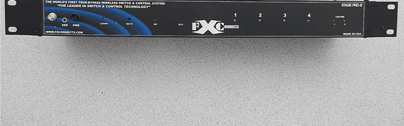
QY4SP8MAIN
Jun 24, 2014True Bypass Analog Programmable Wireless Control System
Equipment Class
DXT - Part 15 Low Power Transceiver, Rx Verified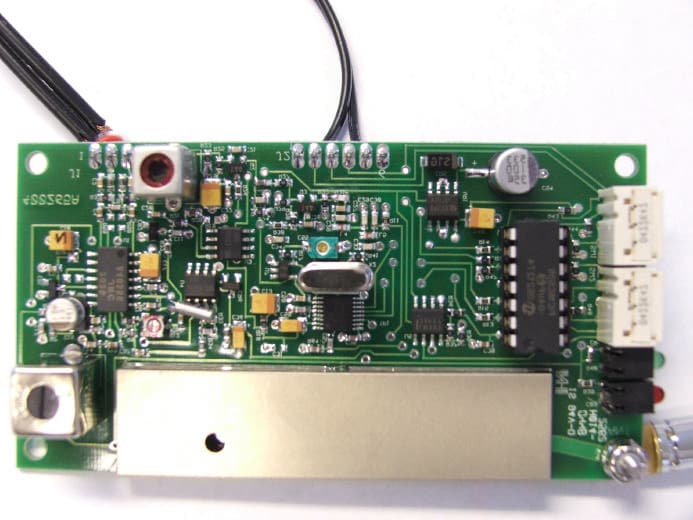
QY4265
Mar 07, 2007900 MHz Audio Transmitter Module
Equipment Class
DXX - Part 15 Low Power Communication Device Transmitter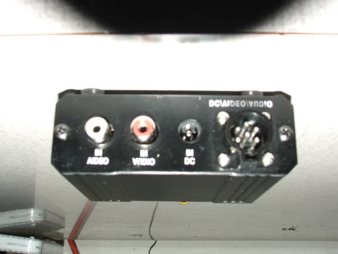
QY4AVT9003A
Jan 04, 2007900 MHz Audio/Video Transmitter
Equipment Class
DXX - Part 15 Low Power Communication Device Transmitter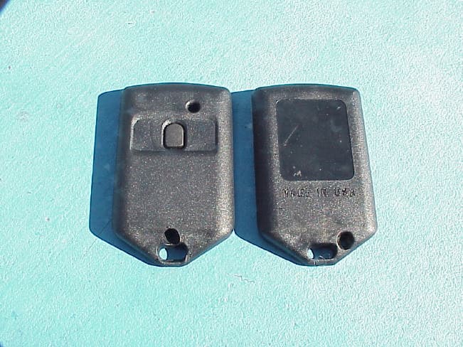
QY4KTX433
Jun 11, 2003Remote Control Transmitter
Equipment Class
DSC - Part 15 Security/Remote Control Transmitter