QY4KTX433Remote Control Transmitter
Applied Wireless, Inc.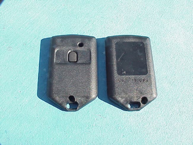
Click to zoom
Application Details
- Equipment Class
- DSC - Part 15 Security/Remote Control Transmitter
- Date of Grant
- Jun 11, 2003
- Application Purpose
- Original Equipment
- Date of Application
- Jun 11, 2003
- Equipment Note
- Remote Control Transmitter
- Frequency Range
- 433.92000000 - 433.92000000
- Company
- Applied Wireless, Inc.
- Country
- United States
Documents & Files
Document Text
Text extracted from the exhibit documents filed with the FCC. Open a document above to read the original.
Users Manual
1250 Avenida Acaso, Unit F, Camarillo, CA 93012 ? Phone (805) 383-9600 ? Fax (805) 383-9001 email: [email protected] ? www.applied-wireless.com USER’S MANUAL Introduction This 433.92 MHz keyfob type transmitter is used in miscellaneous applications requiring short-range remote control of on/off functions. FCC ID: QY4KTX433 INSTRUCTION TO THE USER FCC ID: QY4KTX433 This device complies with Part 15 of the FCC Rules. Operation is subject to the following two conditions: (1) This device may not cause harmful interference and (2) This device must accept any interference received, including interference that may cause undesired operation. The user is cautioned that changes or modifications not expressly approved by the party responsible for compliance could void the user’s authority to operate this equipment. Transmission Range The transmission range of this unit depends upon the environment of the signal path, the type of receiver used and the type of receive antenna used. Using Applied Wireless RCR433 receiver or RX433 module with a Holtek 6034 decoder and a quarter wave vertical antenna, line-of-sight range of 300 feet is normal. By using a quarter wave antenna with ground plane or a dipole antenna will extend the range even further. Non line-of-site applications can have significantly shorter transmission range. Addressing For security purposes, this transmitter is capable of being programmed to one of 6,561 different addresses. The receiver must be programmed to the same address as the transmitter. The default address from the factory for both RCR receivers and KTX series transmitters is 00000000 (all encoder address pins grounded). See application note AN-104 for alternate programming instructions. Troubleshooting ??Verify power by checking transmitter LED when transmitter is operated. ??Verify address codes for transmitter and receiver are the same. ??Eliminate RF interference as a possible problem by checking operation at a different location. 1250 Avenida Acaso, Unit F, Camarillo, CA 93012 ? Phone (805) 383-9600 ? Fax (805) 383-9001 email: [email protected] ? www.applied-wireless.com AppliedWireless The following guidelines are provided here for addressing KTX keychain transmitters and RCR receivers. The encoders and decoders used in these products allow for tri-state addressing. That is, each of the 8 address nodes may be set in either ground, +Vcc or open states. As shipped from the factory, the address nodes for both products are set to ground, and it is not necessary to modify these address for the products to work together. However, if a different address is desired, address nodes on both transmitter and receiver must be set to the same configuration. The following describes how to set an address node to a particular state: Open State To configure a node in the open state, the trace connecting the address node to ground must be cut. +Vcc State To configure a node in the +Vcc state, the trace connecting the address node to ground must be cut AND a connection must be made from the address node to the +Vcc node. A dab of solder is typically used to short across the solder bridge. Ground State As configured from the factory. +Vcc Address Node Ground HT6044 A0................A7 A7....................A0 KTX Board RCR Board Backside View Top View Application Note AN-0104 KTX/RCR Addressing
Block Diagram
3/06/2003 10:54:51a f=0.99 C:/PROGRAM FILES/EAGLE-4.01/projects/block_diagrams/433.92MHZ_TX.sch (Sheet: 1/1)
Cover Letter(s)
1 Scott McCutchan From: Scott McCutchan [[email protected]] Sent: Tuesday, April 15, 2003 12:46 PM To: [email protected] Cc: Ruby Hall Subject: FCC ID: QY4KTX433 Mr. Madlangbayan, In order for processing of this application () to continue, the following issue(s) will have to be addressed: 1) The duty cycle plot submitted is not sufficient. In order to calculate the duty cycle correction factor, please submit a spectrum analyzer plot(s) with the span = 0. One plot (approximately 100 ms) should show the entire pulse train. Include other plots as necessary so that the short and long pulses may be counted and the length of each pulsed may be determined. 2) Please verify that 433.92 is the lowest frequency generated in the device, and that the 433.92 MHz does not get divided down for any reason. 3) The test report indicates that a 120 kHz resolution bandwidth was utilized for radiated emissions testing. As per section 15.35(b), a resolution bandwidth of 1 MHz is to be used for frequency above 1 GHz. 4) Please indicate how the antenna complies with section 15.203. 5) According to the test report, the device was tested while powered by a DC power supply. As per section 15.31(e), battery powered devices shall be tested using a new battery. Please indicate whether tests were performed to determine whether testing with a new battery affects the emissions. 6) Please indicate how the device complies with section 15.231(a)(1), which states that a manually operated device shall employ a switch that will automatically deactivate the transmitter within not more than 5 seconds of being released. 7) The product description in the test report states that the device is used for remote control brake operation in a towed vehicle. This implies that this is an automatically activated transmitter, which does not agree with the rest of the information in the application. Please clarify. The item(s) indicated above must be submitted before processing can continueon the above referenced application. Failure to provide the requestedinformation within 60 days of the original e-mail date may result in application dismissal and forfeiture of the filing fee. Also, please note that partial responses increase processing time and should not be submitted. Please upload responses and/or exhibits to the electronic filing website. Your correspondence number is FCC ID: QY4KTX433-1. If you have any questions, feel free to contact me. Best regards, Scott McCutchan Operations Manager Compatible Electronics TCB (714) 579-1489 fax (714) 579-1850 http://www.celectronics.com Correspondence by Project Project Number: 1698859101 Correspondence Number Memo FCC ID: QY4KTZ433-1 Mr. McCutchen, I am submitting the requested information and data as requested from the original package submittal. Please review the information in the attachments following. Thank You, Joey Madlangbayan
Cover Letter(s)
1250 Avenida Acaso, Unit F, Camarillo, CA 93012 • Phone (805) 383-9600 • Fax (805) 383-9001 email: [email protected] • www.applied-wireless.com Brief Product Description KTX433 Transmitter This 433.925 MHz keyfob type transmitter is used in miscellaneous applications requiring short-range remote control of on/off functions. The keyfob transmitter has two modes of activation, either of which is set at the factory and is not user determinable. In one mode, the keyfob is activated by the press of one of up to three buttons on the transmitter. In the other mode, one function is activated by applying 12VDC to the supply leads through a pushbutton switch, such as a footswitch. In either mode, the transmitter will turn off within 5 seconds of being released. The 433.925 MHz is the lowest frequency generated and does not get divided down to any other frequency. The Antenna is a fixed design and is incorporated onto the PCB board.
Operational Description
1250 Avenida Acaso, Unit F, Camarillo, CA 93012 ? Phone (805) 383-9600 ? Fax (805) 383-9001 email: [email protected] ? www.applied-wireless.com Brief Product Description KTX433 Transmitter This 433.925 MHz battery powered keyfob type transmitter is used in miscellaneous applications requiring short-range remote control of on/off functions.
Schematics
3/06/2003 10:51:52a f=0.99 C:/Program Files/EAGLE-4.01/projects/KTX_SERIES/400038A-433.sch (Sheet: 1/1)
Test Report
DUTY CYCLE PLOTS The bitstream is a 50% duty cycle. The bits are either 0.5 ms on and off or 1 ms on and off intervals. The total on time divided by the total interval time equals 50%. Page 1 of 2 https://celectronics.com:3001/WorldClient.dll?Session=KIVQUNP&View=Message&Number=525/28/03 From: "Mark Simon" <[email protected]> To: <[email protected]> Date: 05/28/2003 10:06 AM Subject: Duty Cycle Plots [2.0] File: TEK00000.BMP Size: 301kContent Type: image/bmp Page 2 of 2 https://celectronics.com:3001/WorldClient.dll?Session=KIVQUNP&View=Message&Number=525/28/03 [3.0] File: TEK00001.BMP Size: 301kContent Type: image/bmp Page 1 of 1 https://celectronics.com:3001/WorldClient.dll?Session=IMULAIH&View=Message&Number=545/28/03 From: "Mark Simon" <[email protected]> To: <[email protected]> Date: 05/28/2003 03:52 PM Subject: TX Bitstream Plot [2.0] File: TEK00002.BMP Size: 301kContent Type: image/bmp
Test Report
FCC ID: QY4KTX433 Report Number: A20919F1 2337 TROUTDALE DRIVE, AGOURA, CALIFORNIA, 91301 • PH: (818) 597-0600 FX: (818) 597-1187 Page 1 of 17 FCC PART 15, SUBPART C TEST REPORT for TRANSMITTER Model: KTX433 FCC ID: QY4KTX433 Prepared for APPLIED WIRELESS 1250 AVENIDA ACASO UNIT F CAMARILLO, CA 93012 Prepared by: _____________________ JOEY J. MADLANGBAYAN Approved by: ____________________ RUBY A. HALL COMPATIBLE ELECTRONICS INC. 2337 TROUTDALE DRIVE AGOURA, CALIFORNIA 91301 (818) 597-0600 DATE: APRIL 9, 2003 REPORT APPENDICES TOTAL BODY A B C D E PAGES 17 2 2 2 8 15 46 This report shall not be reproduced except in full, without the written approval of Compatible Electronics. FCC ID: QY4KTX433 Report Number: A20919F1 2337 TROUTDALE DRIVE, AGOURA, CALIFORNIA, 91301 • PH: (818) 597-0600 FX: (818) 597-1187 Page 2 of 17 TABLE OF CONTENTS Section / Title PAGE GENERAL REPORT SUMMARY 4 SUMMARY OF TEST RESULTS 4 1. PURPOSE 5 2. ADMINISTRATIVE DATA 6 2.1 Location of Testing 6 2.2 Traceability Statement 6 2.3 Cognizant Personnel 6 2.4 Date Test Sample was Received 6 2.5 Disposition of the Test Sample 6 2.6 Abbreviations and Acronyms 6 3. APPLICABLE DOCUMENTS 7 4. Description of Test Configuration 8 4.1 Description of Test Configuration - EMI 8 4.1.1 Cable Construction and Termination 9 5. LISTS OF EUT, ACCESSORIES AND TEST EQUIPMENT 10 5.1 EUT and Accessory List 10 5.2 EMI Test Equipment 11 6. TEST SITE DESCRIPTION 12 6.1 Test Facility Description 12 6.2 EUT Mounting, Bonding and Grounding 12 7. Test Procedures 13 7.1 RF Emissions 13 7.1.1 Conducted Emissions Test 13 7.1.2 Radiated Emissions Test 14 7.1.3 RF Emissions Test Results 15 7.1.4 Sample Calculations 16 8. CONCLUSIONS 17 FCC ID: QY4KTX433 Report Number: A20919F1 2337 TROUTDALE DRIVE, AGOURA, CALIFORNIA, 91301 • PH: (818) 597-0600 FX: (818) 597-1187 Page 3 of 17 LIST OF APPENDICES APPENDIX TITLE A Laboratory Accreditations B Modifications to the EUT C Additional Models Covered Under This Report D Diagrams, Charts and Photos • Test Setup Diagrams • Antenna and Preamplifier Gain Factors • Radiated Emissions Photos E Data Sheets LIST OF FIGURES FIGURE TITLE 1 Plot Map And Layout of Test Site FCC ID: QY4KTX433 Report Number: A20919F1 2337 TROUTDALE DRIVE, AGOURA, CALIFORNIA, 91301 • PH: (818) 597-0600 FX: (818) 597-1187 Page 4 of 17 GENERAL REPORT SUMMARY This electromagnetic emission report is generated by Compatible Electronics Inc., which is an independent testing and consulting firm. The test report is based on testing performed by Compatible Electronics personnel according to the measurement procedures described in the test specifications given below and in the "Test Procedures" section of this report. The measurement data and conclusions appearing herein relate only to the sample tested and this report may not be reproduced in any form except in full, without the written permission of Compatible Electronics. This report must not be used to claim product endorsement by NVLAP or any other agency of the U.S. Government. Device Tested: Transmitter Model: KTX433 S/N: None Product Description: This is a Transmitter. Modifications: The EUT was not modified during the testing. Manufacturer: Applied Wireless 1250 Avenida Acaso Unit F Camarillo, CA 93012 Test Date: September 19, 2002 Test Specifications: EMI requirements FCC CFR Title 47, Part 15 Subpart C Test Procedure: ANSI C63.4: 2000. Test Deviations: The test procedure was not deviated from during the testing. SUMMARY OF TEST RESULTS TEST DESCRIPTION RESULTS 1 Radiated RF Emissions, 433.92 MHz to 4339.20 MHz Complies with the limits of FCC CFR Title 47, Part 15 Subpart C 15.205 and 15.231. FCC ID: QY4KTX433 Report Number: A20919F1 2337 TROUTDALE DRIVE, AGOURA, CALIFORNIA, 91301 • PH: (818) 597-0600 FX: (818) 597-1187 Page 5 of 17 1. PURPOSE This document is a qualification test report based on the Electromagnetic Interference (EMI) tests performed on the Transmitter Model: KTX433. The EMI measurements were performed according to the measurement procedure described in ANSI C63.4: 2000. The tests were performed in order to determine whether the electromagnetic emissions from the equipment under test, referred to as EUT hereafter, are within the specification limits defined in FCC CFR Title 47, Part 15 Subpart C (15.205 and 15.231). FCC ID: QY4KTX433 Report Number: A20919F1 2337 TROUTDALE DRIVE, AGOURA, CALIFORNIA, 91301 • PH: (818) 597-0600 FX: (818) 597-1187 Page 6 of 17 2. ADMINISTRATIVE DATA 2.1 Location of Testing The EMI tests described herein were performed at the test facility of Compatible Electronics, 2337 Troutdale Drive, Agoura, California 91301. 2.2 Traceability Statement The calibration certificates of all test equipment used during the test are on file at the location of the test. The calibration is traceable to the National Institute of Standards and Technology (NIST). 2.3 Cognizant Personnel Applied Wireless David Nichols President Mark Simon Vice President of Engineering Compatible Electronics Inc. Andre D. Khan Test Technician Joey J. Madlangbayan Test Engineer Ruby A. Hall Lab Manager 2.4 Date Test Sample was Received The test sample was received on September 19, 2002. 2.5 Disposition of the Test Sample The test sample remains at Compatible Electronics, Inc. 2.6 Abbreviations and Acronyms The following abbreviations and acronyms may be used in this document. RF Radio Frequency EMI Electromagnetic Interference EUT Equipment Under Test P/N Part Number S/N Serial Number HP Hewlett Packard ITE Information Technology Equipment CML Corrected Meter Limit LISN Line Impedance Stabilization Network FCC ID: QY4KTX433 Report Number: A20919F1 2337 TROUTDALE DRIVE, AGOURA, CALIFORNIA, 91301 • PH: (818) 597-0600 FX: (818) 597-1187 Page 7 of 17 3. APPLICABLE DOCUMENTS The following documents are referenced or used in the preparation of this EMI Test Report. SPEC TITLE FCC CFR Title 47, Part 15 Subpart C. FCC Rules – Intentional Radiators. ANSI C63.4 2000 Methods of measurement of radio-noise…
Text truncated - open the document above for the full version.
Contact Information
Applicant
David Nichols(President)
Technical Contact
Compatible ElectronicsJoey J Madlangbayan
[email protected]818-597-0600
2337 Troutdale Drive · Agoura, California · United States
Test Firm
Compatible ElectronicsRuby Hall
Technical Specifications
| # | Rule Parts | Frequency Range | Power Output |
|---|---|---|---|
| 1 | 15.231 | 433.92 MHz - 433.92 MHz | - |
Other Applications from Applied Wireless, Inc.
QY4KTXW303
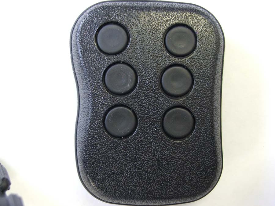
Jan 11, 2015Remote Transmitter
Equipment Class
DSC - Part 15 Security/Remote Control Transmitter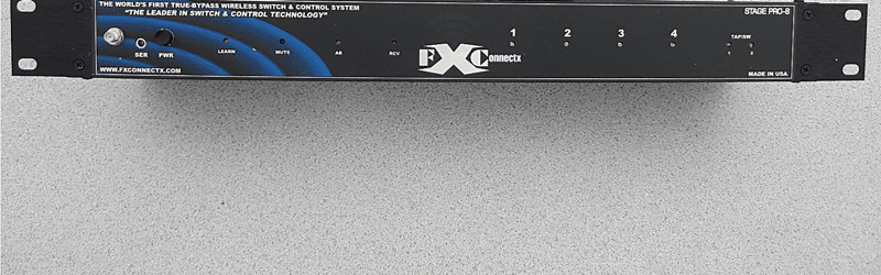
QY4SP8MAIN
Jun 24, 2014True Bypass Analog Programmable Wireless Control System
Equipment Class
DXT - Part 15 Low Power Transceiver, Rx Verified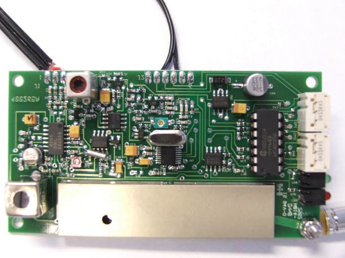
QY4265
Mar 07, 2007900 MHz Audio Transmitter Module
Equipment Class
DXX - Part 15 Low Power Communication Device Transmitter
QY4AVT9003A
Jan 04, 2007900 MHz Audio/Video Transmitter
Equipment Class
DXX - Part 15 Low Power Communication Device Transmitter