QY4SP8MAINTrue Bypass Analog Programmable Wireless Control System
Applied Wireless, Inc.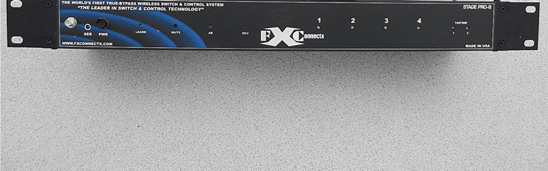
Click to zoom
Application Details
- Equipment Class
- DXT - Part 15 Low Power Transceiver, Rx Verified
- Date of Grant
- Jun 24, 2014
- Application Purpose
- Original Equipment
- Date of Application
- Jun 23, 2014
- Equipment Note
- True Bypass Analog Programmable Wireless Control System
- Frequency Range
- 2411.00000000 - 2481.00000000
- Company
- Applied Wireless, Inc.
- Country
- United States
Documents & Files
Document Text
Text extracted from the exhibit documents filed with the FCC. Open a document above to read the original.
Users Manual
Copyright 2014 by FXConnectX LLC. All Rights Reserved. Page 1 STAGEPRO-8 TRUE BYPASS ANALOG PROGRAMMABLE WIRELESS CONTROL SYSTEM User Guide - Revision: February-2014 Www.FXConnectX.com MADE WITH PRIDE IN THE UNITED STATES OF AMERICA THIS TECHNOLOGY IS FULLY PROTECTED UNDER US PATENT LAWS -PATENT PENDING- Copyright 2014 by FXConnectX LLC. All Rights Reserved. Page 2 FCC STATEMENTS: Main Controller: FCC ID: QY4SP8MAIN “This device complies with Part 15 of the FCC Rules. Operation is subject to the following two conditions: (1) this device may not cause harmful interference, and (2) this device must accept any interference received, including interference that may cause undesired operation.” Pedal Board (Model SP8F) and Body Pack (Model (SP8BP6 and SP8BP8): These products incorporate transmitter module FCC ID: UY124 This device complies with Part 15 of the FCC Rules. Operation is subject to the following two conditions: (1) This device may not cause harmful interference and (2) This device must accept any interference received, including interference that may cause undesired operation. INSTRUCTION TO THE USER Note: This equipment has been tested and found to comply with the limits for a Class B digital device, pursuant to part 15 of the FCC Rules. These limits are designed to provide reasonable protection against harmful interference in a residential installation. This equipment generates, uses, and can radiate radio frequency energy and, if not installed and used in accordance with the instructions, may cause harmful interference to radio communications. However, there is no guarantee that interference will not occur in a particular installation. If this equipment does cause harmful interference to radio or television reception, which can be determined by turning the equipment off and on, the user is encouraged to try to correct the interference by one or more of the following measures: —Reorient or relocate the receiving antenna. —Increase the separation between the equipment and receiver. —Connect the equipment into an outlet on a circuit different from that to which the receiver is connected. —Consult the dealer or an experienced radio/TV technician for help. Changes or modifications not expressly approved by FXConnectX could void the user's authority to operate the equipment. Copyright 2014 by FXConnectX LLC. All Rights Reserved. Page 3 Introduction The FXconnectX StagePro8 system has been designed to provide wirelessly controlled and transparent True-Bypass audio loop switching technology for pedal boards, guitar/audio racks, recording studios, or any application up to 200 feet away! “Freedom” from the board! Be anywhere on stage (or in the audience) and from your finger tips, guitars, or foot controllers you can now switch amp channels, mute your whole rig, set a tap tempo, and control your pedals connected to four programmable True-Bypass loops! This manual will guide you through the use of your new system. We thank you for your purchase! We are here for you and are available to answer any questions you may have. Please contact us by phone, email, or feel free to view the HELP videos on our web site. Operational Overview The StagePro8’s four true-bypass audio loops can be configured as desired. The loops have been designed to ensure true audio transparency. Each loop is arranged in series (Loop 1 to Loop 4). Each loop’s selection is determined by the settings on your Body Pack(s) or Floor Switch unit(s). Active loops and programmed patches are indicated by the LED’s displayed on the front panel of the main unit and Floor units. StagePro8 has a built-in Amp A/B switcher and can be configured for Normally Open or Normally Closed operation (to accommodate various types of channel switching needs). The system can also be programmed with “patches” containing different combinations of loops and external switching combinations (Eliminates the “tap” dance). Each loop can also be set to operate in Toggle mode (like a normal on/off pedal) or set to momentary mode (to tap a tempo or similar). Any time an unused loop is selected (no connections are made to these jacks), that loop will be in a default full True-Bypass mode and will be totally removed from the audio chain. Loops are “Half-Normalized” in order to accommodate many connection possibilities. In the event of a loss of power longer than 3 seconds, or whenever the power switch is switched off, the unit will default into full True-Bypass mode: Input will be directly routed to Output. Main Unit Front Panel Antenna: The antenna can be removed for storage and repositioned as needed, but when in use it must be in the upright position (never sideways). SER: Serial Jack. An optional Serial Fail-Safe cable can be connected from this jack to the Serial jack on any single Floor Unit. When a cable is used all wireless functionality is bypassed. Cables are available on our web site. Copyright 2014 by FXConnectX LLC. All Rights Reserved. Page 4 PWR: Power On/Off switch LEARN: The Learn LED is illuminated when the L-SW (Learn Switch) is pressed and learn mode is active. MUTE: The Mute LED is illuminated when the system Soft Mute is active. Soft Mute only affects output jack 2 (The second jack); jack 1 is not muted. This enables the non- muted output to still drive a signal chain or be used for tuning. AB: The AB LED is illuminated when the AB switch is active. RCV: The Receive LED illuminates when the system is receiving commands from a remote. 1, 2, 3, 4, TS1, TS2: These LED’s are illuminated whenever these loops or functions are active. Main Unit Rear Panel GND:ISO (Isolated) This switch isolates audio ground from common chassis ground. Useful when troubleshooting system ground issues or performing where grounding is causing loud hum or noise. COM connects audio ground to common chassis ground. AB: This switch selects Normally Open (NO) or Normally Closed (NC) Tip to Sleeve orientation of the AB jack. Most amps use a NO style co…
Text truncated - open the document above for the full version.
Cover Letter(s)
Non-Conformities FCC ID: QY4SP8MAIN (CKC CS Ref # 94710-25-FCC) OK ID # Non-Conformity or Comment Submitted Response Respondent / Date of Response x 4 Please clarify antenna connector style (if removable). RPSMA Mark Simon, 4/14/14
Test Report
This report contains a total of 30 pages and may be reproduced in full only. Partial reproduction may only be done with the written consent of CKC Laboratories, Inc. FX ConnectX LLC TEST REPORT FOR Wireless Main 19" Rack Controller Model: STAGE PRO-8 WIRELESS CONTROL SYSTEM Tested To The Following Standards: FCC Part 15 Subpart C Section(s) 15.207 AND 15.249 Report No.: 94710-22 Date of issue: February 13, 2014 This test report bears the accreditation symbol indicating that the testing performed herein meets the test and reporting requirements of ISO/IEC 17025 under the applicable scope of EMC testing for CKC Laboratories, Inc. We strive to create long-term, trust based relationships by providing sound, adaptive, customer first testing services. We embrace each of our customers’ unique EMC challenges, not as an interruption to set processes, but rather as the reason we are in business. Page 2 of 30 Report No.: 94710-22 TABLE OF CONTENTS Administrative Information .......................................................................................................................... 3 Test Report Information ............................................................................................................................................ 3 Report Authorization ................................................................................................................................................. 3 Test Facility Information ............................................................................................................................................ 4 Software Versions ...................................................................................................................................................... 4 Site Registration & Accreditation Information .......................................................................................................... 4 Summary of Results ................................................................................................................................................... 5 Conditions During Testing.......................................................................................................................................... 5 Equipment Under Test ............................................................................................................................................... 6 Peripheral Devices ..................................................................................................................................................... 6 FCC Part 15 Subpart C ................................................................................................................................... 7 15.207 AC Conducted Emissions ................................................................................................................................ 7 15.249(a) Fundamental Field Strength .................................................................................................................... 14 15.215(c) Occupied Bandwidth ............................................................................................................................... 19 15.249(d) Field Strength of Spurious Emissions & Band Edge ................................................................................. 23 Supplemental Information .......................................................................................................................... 29 Measurement Uncertainty ...................................................................................................................................... 29 Emissions Test Details .............................................................................................................................................. 29 Page 3 of 30 Report No.: 94710-22 ADMINISTRATIVE INFORMATION Test Report Information REPORT PREPARED FOR: REPORT PREPARED BY: FX ConnectX LLC 1250 Avenida Acaso, Ste F Camarillo, CA 93012 Morgan Tramontin CKC Laboratories, Inc. 5046 Sierra Pines Drive Mariposa, CA 95338 REPRESENTATIVE: David Nichols Project Number: 94710 Customer Reference Number: 190767 DATE OF EQUIPMENT RECEIPT: January 24, 2014 DATE(S) OF TESTING: January 24, 2014 Report Authorization The test data contained in this report documents the observed testing parameters pertaining to and are relevant for only the sample equipment tested in the agreed upon operational mode(s) and configuration(s) as identified herein. Compliance assessment remains the client’s responsibility. This report may not be used to claim product endorsement by A2LA or any government agencies. This test report has been authorized for release under quality control from CKC Laboratories, Inc. Steve Behm Director of Quality Assurance & Engineering Services CKC Laboratories, Inc. Page 4 of 30 Report No.: 94710-22 Test Facility Information Our laboratories are configured to effectively test a wide variety of product types. CKC utilizes first class test equipment, anechoic chambers, data acquisition and information services to create accurate, repeatable and affordable test results. TEST LOCATION(S): CKC Laboratories, Inc. 22116 23rd Drive S.E., Suite A Bothell, WA 98021-4413 Software Versions CKC Laboratories Proprietary Software Version EMITest Emissions 5.00.14 Immunity 5.00.07 Site Registration & Accreditation Information Location CB # TAIWAN CANADA FCC JAPAN Bothell US0081 SL2-IN-E-1145R 3082C-1 318736 A-0148 Page 5 of 30 Report No.: 94710-22 SUMMARY OF RESULTS Standard / Specification: FCC Part 15 Subpart C Test Procedure/Method Description Results 15.207 / ANSI C63.4 Conducted Emissions Pass 15.249(a) / 558074 DO1 DTS Measurement Guidance V01 Fundamental Field Strength Pass 15.215(c) Occupied Bandwidth Pass 15.249(d) / 558074 DO1 DTS Measurement Guidance V01 Field Strength of Spurious Emissions & Band Edge Pass Conditions During Testing This list is a summary…
Text truncated - open the document above for the full version.
Contact Information
Applicant
David Nichols(President)
Technical Contact
Applied WIreless, Inc.David Nichols
[email protected]805-383-9600
1250 Avenida Acaso, Unit F · Camarillo, California · United States
Test Firm
CKC Laboratories, Inc.Steve Behm
Technical Specifications
| # | Rule Parts | Frequency Range | Power Output |
|---|---|---|---|
| 1 | 15C | 2.41 GHz - 2.48 GHz | - |
Other Applications from Applied Wireless, Inc.
QY4KTXW303
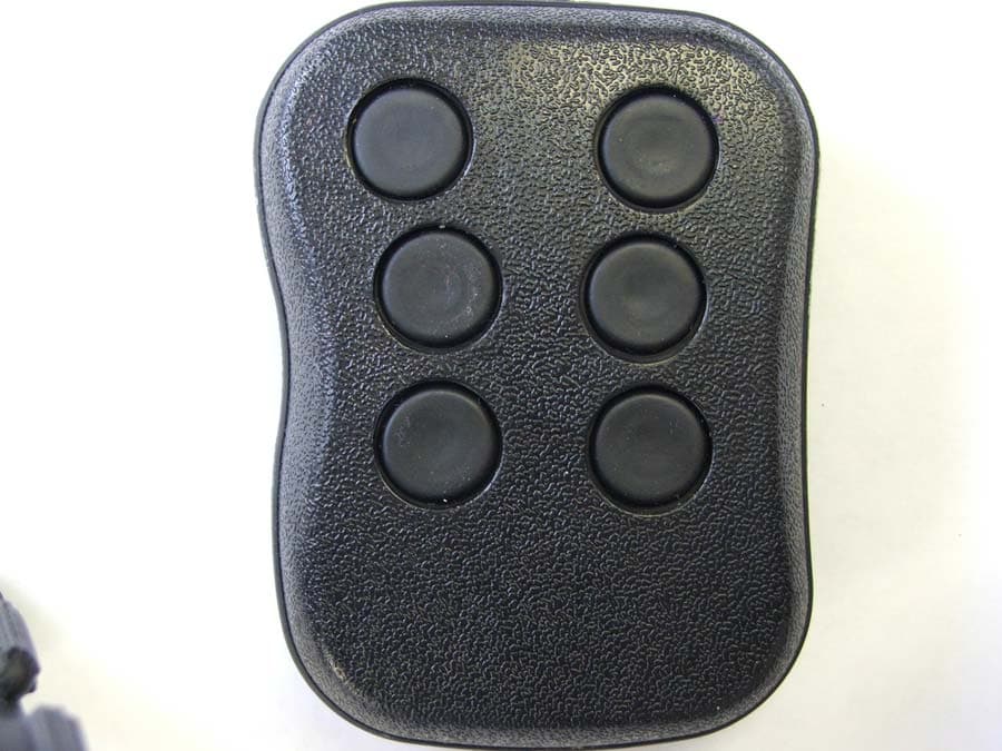
Jan 11, 2015Remote Transmitter
Equipment Class
DSC - Part 15 Security/Remote Control Transmitter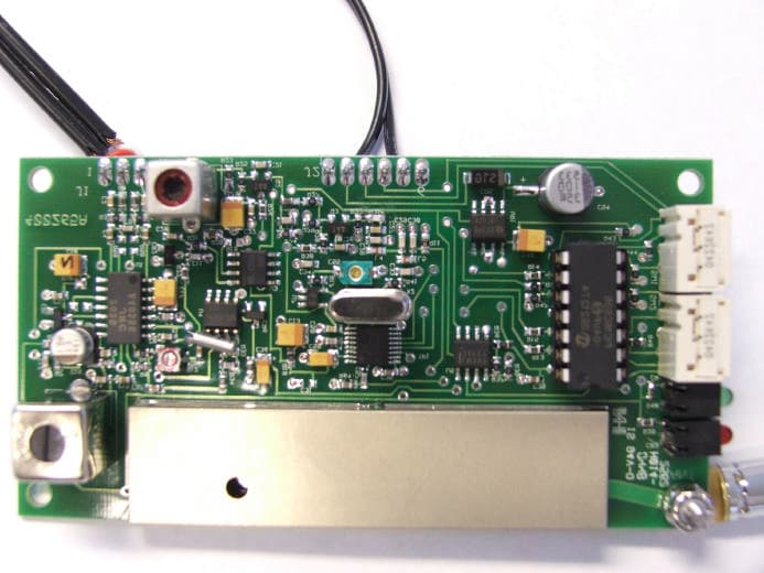
QY4265
Mar 07, 2007900 MHz Audio Transmitter Module
Equipment Class
DXX - Part 15 Low Power Communication Device Transmitter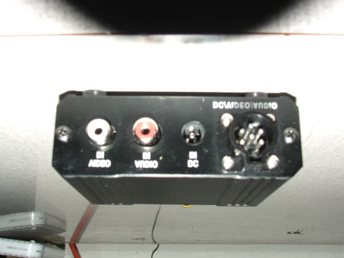
QY4AVT9003A
Jan 04, 2007900 MHz Audio/Video Transmitter
Equipment Class
DXX - Part 15 Low Power Communication Device Transmitter
QY4KTX433
Jun 11, 2003Remote Control Transmitter
Equipment Class
DSC - Part 15 Security/Remote Control Transmitter