QYPPWA0701Bluetooth Access Point
Polymap Wireless LLC
Click to zoom
Application Details
- Equipment Class
- DSS - Part 15 Spread Spectrum Transmitter
- Date of Grant
- Sep 14, 2003
- Application Purpose
- Original Equipment
- Date of Application
- Sep 14, 2003
- Equipment Note
- Bluetooth Access Point
- Frequency Range
- 2402.00000000 - 2480.00000000
- Company
- Polymap Wireless LLC
- Country
- United States
Documents & Files
Document Text
Text extracted from the exhibit documents filed with the FCC. Open a document above to read the original.
Users Manual
User Manual Welcome to the wonderful world of wireless! Your Polymap Wireless enhanced device is intended to work with the enclosed Access Point to allow data to be seamlessly transferred to your healthcare professional, without any intervention on your part. Once the Access point is installed, and the medical device is within a 30 foot radius of it, any unsent data will be automatically transferred to the Access Point. The Access Point will then wait for the telephone line to become free, and transfer the data over telephone to the data center. Wireless transmission range is always reduced by obstructions, so a clear line of sight between the measurement device and the Access Point will give the best results. Installation and setup The effective radio range of the Access Point and the matching medical devices is around 30 feet (10 meters). This being the case, please choose a location in your house that is centrally located, or close to where the measuring devices will be used. 1) Connect a telephone cord between the Access Point and a telephone jack on the wall. An extra telephone outlet is provided on the back of the Access Point so you can plug a telephone into the same outlet. NOTE: this device is not designed for connection to digital PBX systems, such as might be found in an office. 2) Connect the power cord to the back of the unit, and plug it into a regular 120V outlet. Figure 1: Connecting the Access Point. Leftmost connector is for power, telephone line goes in either telephone connector; optionally, a telephone can be connected to the second telephone connector. NOTE: telephone will not operate unless the Access Point is also connected to a wall telephone socket. Usage In normal use, there is no intervention required by the user. Nonetheless, indicator lights are provided to give the user some sense of the correct operation of the device. There are four indicator lights on the front panel of the Access Point. These are, respectively: POWER, RADIO, TELEPHONE, and ERROR. POWER (Green) Always on in normal operation RADIO (Green) Blinks roughly once per second, more blinking while data is being received TELEPHONE (Green) Blinks when the device is connecting to the server to transfer its data. Solid while the device is connected and transferring data (usually only a few seconds) ERROR (Red) Comes on when data was received by the Access Point but not successfully transferred to the data center. This will occur, for example, when the telephone is in use, or there is some other congestion on the network. The Access point will keep trying, every few minutes, until it succeeds in transferring the data. Note that data is never lost. Figure 1: Access point, showing the four indicator lights: POWER, RADIO, TELEPHONE, and ERROR. In normal operation, the leftmost, or POWER light, will remain on, and the second light (RADIO), will blink roughly once per second. During the data transfer, the RADIO light will blink in other patterns. The TELEPHONE light is used to indicate usage of the telephone, and the ERROR light is used to indicate a data transfer error. Note that data transfer errors are expected to occur, and should not be a concern unless they persist. If the ERROR light comes on the first time the device is used, the most likely explanation is that it is not correctly connected to a telephone jack. Regulatory Statements “Modifications made to the product, unless expressly approved by Polymap Wireless, could void the user’s authority to operate the equipment” The following apply to the Polymap Wireless Access Point IC: 4552A-PWA-0701 FCC ID: QYPPWA0701 This device complies with Part 15 of the FCC Rules. Operation is subject to the following two conditions: (1) This device may not cause harmful interference, and (2) this device must accept any interference received, including interference that may cause undesired operation. NOTE: This equipment has been tested and found to comply with the limits for a Class B digital device , pursuant to Part 15 of the FCC Rules. These limits are designed to provide reasonable protection against harmful interference in a residential installation. This equipment generates, uses, and can radiate radio frequency energy and, if not installed and used in accordance with the instructions, may cause harmful interference to radio communications. However, there is no guarantee that interference will not occur in a particular installation. If this equipment does cause harmful interference to radio or television reception, which can be determined by turning the equipment off and on, the user is encouraged to try and correct the interference by one or more of the following measures: — Reorient or locate the receiving antenna. — Increase the separation between the equipment and receiver. — Connect the equipment into an outlet on a circuit different from that to which the receiver is connected. — Consult the dealer or an experienced radio/TV technician for help. This Class B digital apparatus complies with Canadian ICES-003 Cet appareil numérique de la classe B est conforme à la norme NMB-003 du Canada The following apply to the Polymap Wireless Remote Unit Polymap Wireless 310 S. Williams Blvd. Ste. 346 Tucson, AZ 85711 (520) 747-1811 PWR-07-01 IC: 4552A-PWR-0701 FCC ID: QYPPWR0701 We declare under our sole responsibility that the product Polymap Wireless Remote PWR-07-01 complies with Part 15 of the FCC Rules. Operation is subject to the following two conditions: (1) This device may not cause harmful interference, and (2) this device must accept any interference received, including interference that may cause undesired operation. ICES-003 B / NMB-003 B Tested to comply with FCC Standards For Home or Office Use NOTE: This equipment has been tested and found to comply with the limits for a Class B digital device , pursuant to Part 15 of the FCC Rules. These limits are designed to provide reasonable protection against harmful interference in a residential installation.…
Text truncated - open the document above for the full version.
Cover Letter(s)
September 11, 2003 RE: ATCB Comments QYPPWA0701 After reviewing your comments, please find our responses below. 1). Photos are not normally held confidential. Justification must be provided to hold photographs as confidential. Justification could include: (1) special tools required to open the case, (2) the circuitry may be potted or covered in epoxy, (3) the company professionally installs the product and it is not directly viewable by the public during use or after use, and (4) the product may involve new technology. Trade secret is not sufficient justification. New technology, if it is documented, can be justification for holding photos as confidential, but for example, a basic FM transmitter is not new technology. Please provide an updated letter of confidentiality that justifies why the antenna photographs should be held as confidential, or as an alternative, you may use a black marker to "black out" the top of any readable components and provide new internal photographs. Please let us know how you wish to proceed with this issue. The confidentiality request has been updated to remove photographs from its scope. 2) The label states "FCC: QYPPWA0701". Please correct the label to state "FCC ID: QYPWA0701". The label has been updated and a new file has been uploaded. 3) Please provide higher resolution test configuration photographs if available. A photograph showing a close-up of the device on the test table has been uploaded. Note that this picture does not show the telephone line connected (although preliminary testing demonstrated that the emissions form the device were not significantly affected by the presence of this cable). 4) Please provide information regarding the RBW and VBW settings used for radiated emissions measurements. RBW=VBW=1MHz for peak measurements above 1GHz, VBW reduced to 10Hz for average measurements.. Page 2 of 3 5) The test report appears to be missing the following: output power measurements, 20 dB bandwidth, channel occupancy, channel separation, channel dwell time, number of channels, etc. as shown in the previous related report and the summary page of this report. Please provide. The data was omitted from the report by mistake. The report has been revised to include this data. 6) Given the missing output power in the test report, it is uncertain of the method used. However the power listed on the 731 form is less than 0 dBm, while the chip used in this device appears to have an output of 4 dBm. Additionally, the desired method is to use far field equations to determine a conducted output power. Please explain and/or correct the necessary exhibits. The output power was measured directly via a connector on the circuit board. The test data has been corrected to include the missing data (refer to (5) above). 7) Given the output power of this device (around 4 dBm) and antenna gain of 6 dBi, the expected output power of this device will exceed 5 mW. However, this device is not really considered a portable device given its design and use, and should be considered as a mobile device. Please correct the RF exposure exhibit for this issue by calculating the power density at 20 cm. Additionally, the users manual should include the typical statements required for mobile devices ("This device and its antenna must not be collocated or operating in conjunction with any other antenna or transmitter"). The output power was measured directly via a connector on the circuit board to be –2.4dBm. The chipset specifications may indicate an output power of ~4dBm but this level was never measured (we did have a couple of units available and the output power was consistent between the units we had). With this in mind is it possible to keep the device listed as a portable device since the output power measured (-2.4dBm) and calculated maximum eirp(3.6dBm) remain below 5mW (7dBm)? This avoids having to enter any rf exposure information in the user’s manual. 8) FYI, This certification only covers the TX portion of the device and does not cover any requirements necessary for the telecom portion of the device. Noted, Part 68 registration is being handled separately. Page 3 of 3 The following files have been uploaded to the ATCB website to support these responses: • LABEL AND LABEL LOCATION-revised.pdf • Close-up.JPG • Response.doc • R52139 (revised).pdf If you have nay further questions, please do not hesitate to contact me via [email protected]. Regards, Mark Briggs
Cover Letter(s)
September 12, 2003 RE: ATCB Comments QYPPWA0701 dated September 12, 2003 After reviewing your comments, please find our responses below. 1) The modified confidentiality letter referenced in the response does not appear to have been provided. Please provide. The confidentiality request has been uploaded – sorry for the delay. 2) The antenna description on Page 2 of 21 was changed in the revised report and not now longer applies to this device. Please correct. The description of the access point antenna has been corrected. 3) An output level adjustment was shown in the power output results. Please confirm this setting used gives the highest output power expected for use with this device. To the best of our knowledge, and the manufacturer’s, the control software for the BlueTooth device in test mode was adjusted to give the maximum output power. 4) The information on page 11 & 15 of 21 says the device has 78 channels. Note that this type of device requires to have 79 channels minimum. The number of channels was verified to be 79. All test data references to the number of channels have been updated to show the correct number. Page 2 of 2 5) The plots shown on page 18 & 21 of 21 show a large difference between peak and average readings. This suggests that the transmitter output was in a pulse mode of operation vs. CW or 100% TX signal. Typically if the device is not in a CW or 100% TX duty cycle, a 10 Hz VBW is not considered acceptable for the measurements. Note that 1/(TX on Time) must be > VBW setting to be considered valid. This would likely require a VBW of > 2 kHz for this device. It appears that average measurements may not have been properly taken. However, given that this is a bluetooth based device, we can assume that bluetooth operation theory applies. Bluetooth has different packet lengths that may be used in various modes. The theory of operation for Bluetooth states that their may be 1, 3, or 5 slots used per transmit depending on the mode of operation. For a DH1 packet the TX is on 0.625 us per 49 mS per channel, while for a DH5 packet the TX is on 0.625 * 5 per 247 ms per channel. These duty cycles equal the following: 20 log (.625/49) = 37.9 dB or 20 log (3.125/100) = -30 dB. All are greater than the 20 dB difference between the peak and average limits. Therefore if peak measurements meet, it is assumed that all average measurements will as well since the difference in limits is 20 dB, while the duty cycle correction exceeds this. It may be best to remove all average measurements and simply add a note to the fact. The difference between peak and average readings for the fundamental signal show only a minimal difference so the radiated data should not have required the use of an average bandwidth greater than 10Hz to avoid pulse desensitization. The test data has been updated to remove the average band-edge plots and the band edge levels for radiated spurious emissions were re-calculated based on the peak band-edge delta. The calculated levels agree with the original measured levels, confirming that the device was, in fact, transmitting continuously during the radiated emissions tests. The following files have been uploaded to the ATCB website to support these responses: • Response #2.doc • R52139 (Revision 2).pdf If you have further questions, please do not hesitate to contact me via [email protected] . Regards, Mark Briggs
Cover Letter(s)
American Telecommunications Certification Body Inc. 6731 Whittier Ave, McLean, VA 22101 September 10, 2003 RE: Polymap Wireless LLC FCC ID: QYPPWR0701 After a review of the submitted information, I have a few comments on the above referenced Application. 1) Photos are not normally held confidential. Justification must be provided to hold photographs as confidential. Justification could include: (1) special tools required to open the case, (2) the circuitry may be potted or covered in epoxy, (3) the company professionally installs the product and it is not directly viewable by the public during use or after use, and (4) the product may involve new technology. Trade secret is not sufficient justification. New technology, if it is documented, can be justification for holding photos as confidential, but for example, a basic FM transmitter is not new technology. Please provide an updated letter of confidentiality that justifies why the antenna photographs should be held as confidential, or as an alternative, you may use a black marker to "black out" the top of any readable components and provide new internal photographs. Please let us know how you wish to proceed with this issue. 2) The label states "FCC: QYPPWA0701". Please correct the label to state "FCC ID: QYPWA0701". 3) Please provide higher resolution test configuration photographs if available. 4) Please provide information regarding the RBW and VBW settings used for radiated emissions measurements. 5) The test report appears to be missing the following: output power measurements, 20 dB bandwidth, channel occupancy, channel separation, channel dwell time, number of channels, etc. as shown in the previous related report and the summary page of this report. Please provide. 6) Given the missing output power in the test report, it is uncertain of the method used. However the power listed on the 731 form is less than 0 dBm, while the chip used in this device appears to have an output of 4 dBm. Additionally, the desired method is to use far field equations to determine a conducted output power. Please explain and/or correct the necessary exhibits. 7) Given the output power of this device (around 4 dBm) and antenna gain of 6 dBi, the expected output power of this device will exceed 5 mW. However, this device is not really considered a portable device given its design and use, and should be considered as a mobile device. Please correct the RF exposure exhibit for this issue by calculating the power density at 20 cm. Additionally, the users manual should include the typical statements required for mobile devices ("This device and its antenna must not be co- located or operating in conjunction with any other antenna or transmitter"). 8) FYI, This certification only covers the TX portion of the device and does not cover any requirements necessary for the telecom portion of the device. Timothy R. Johnson Examining Engineer mailto: [email protected] The items indicated above must be submitted before processing can continue on the above referenced application. Failure to provide the requested information may result in application termination. Correspondence should be considered part of the permanent submission and may be viewed from the Internet after a Grant of Equipment Authorization is issued. Please do not respond to this correspondence using the email reply button. In order for your response to be processed expeditiously, you must submit your documents through the AmericanTCB.com website. Also, please note that partial responses increase processing time and should not be submitted. Any questions about the content of this correspondence should be directed to the sender.
Cover Letter(s)
American Telecommunications Certification Body Inc. 6731 Whittier Ave, McLean, VA 22101 September 12, 2003 RE: Polymap Wireless LLC FCC ID: QYPPWR0701 After a review of the submitted information, I have a few comments on the above referenced Application. 1) The modified confidentiality letter referenced in the response does not appear to have been provided. Please provide. 2) The antenna description on Page 2 of 21 was changed in the revised report and not now longer applies to this device. Please correct. 3) An output level adjustment was shown in the power output results. Please confirm this setting used gives the highest output power expected for use with this device. 4) The information on page 11 & 15 of 21 says the device has 78 channels. Note that this type of device requires to have 79 channels minimum. 5) The plots shown on page 18 & 21 of 21 show a large difference between peak and average readings. This suggests that the transmitter output was in a pulse mode of operation vs. CW or 100% TX signal. Typically if the device is not in a CW or 100% TX duty cycle, a 10 Hz VBW is not considered acceptable for the measurements. Note that 1/(TX on Time) must be > VBW setting to be considered valid. This would likely require a VBW of > 2 kHz for this device. It appears that average measurements may not have been properly taken. However, given that this is a bluetooth based device, we can assume that bluetooth operation theory applies. Bluetooth has different packet lengths that may be used in various modes. The theory of operation for Bluetooth states that their may be 1, 3, or 5 slots used per transmit depending on the mode of operation. For a DH1 packet the TX is on 0.625 us per 49 mS per channel, while for a DH5 packet the TX is on 0.625 * 5 per 247 ms per channel. These duty cycles equal the following: 20 log (.625/49) = 37.9 dB or 20 log (3.125/100) = -30 dB. All are greater than the 20 dB difference between the peak and average limits. Therefore if peak measurements meet, it is assumed that all average measurements will as well since the difference in limits is 20 dB, while the duty cycle correction exceeds this. It may be best to remove all average measurements and simply add a note to the fact. Timothy R. Johnson Examining Engineer mailto: [email protected] The items indicated above must be submitted before processing can continue on the above referenced application. Failure to provide the requested information may result in application termination. Correspondence should be considered part of the permanent submission and may be viewed from the Internet after a Grant of Equipment Authorization is issued. Please do not respond to this correspondence using the email reply button. In order for your response to be processed expeditiously, you must submit your documents through the AmericanTCB.com website. Also, please note that partial responses increase processing time and should not be submitted. Any questions about the content of this correspondence should be directed to the sender.
Cover Letter(s)
August 20, 2003 American Telecommunications Certification Body, Inc. 6731 Whittier Avenue Suite C110 McLean, VA 22101 To who it may concern: Please be advised that Polymap Wireless LLC authorizes Elliott Laboratories to act on our behalf, until otherwise notified, for applications submitted to American Telecommunications Certification Body, Inc. (ATCB). We certify that we are not subject to denial of federal benefits, that includes FCC benefits, pursuant to Section 5301 of the Anti-Drug Abuse ACT of 1988, U.S.C. 862. Further, no party, as defined in 47 CFR 1.2002(b), to the application is subject to denial of federal benefits, that includes FCC benefits. Thank you for your attention to this matter Sincerely, Pierre Landau, PhD President 310 S. Williams Blvd. Suite 346 Tucson, AZ 85711 t: 520.747.1811 f: 520.747.9408 www.polymap.net
Cover Letter(s)
August 20, 2003 American Telecommunications Certification Body, Inc. 6731 Whittier Avenue Suite C110 McLean, VA 22101 RE: Certification Application FCC ID: QYPPWA0701 and QYPPWR0701 Please be advised that the following information is to be held confidential and behalf of Polymap Wireless LLC: • Circuit diagrams • Block diagrams • Theory of operation The application contains technical information which Polymap Wireless LLC deems to be trade secrets and proprietary. If made public, the information might be used to the disadvantage of the applicant in the market place. Thank you for your attention to this matter. Sincerely, Pierre Landau, PhD President 310 S. Williams Blvd. Suite 346 Tucson, AZ 85711 t: 520.747.1811 f: 520.747.9408 www.polymap.net
ID Label/Location Info
LABEL AND LABEL LOCATION Label (see below) is located here on the bottom side of Base-Station/Access Point. It is made from a white polyester with lamination with a heavy-duty pressure sensitive adhesive to provide a permanent labeling solution. 1.75” 0.75”
Operational Description
BLUETOOTH APPROVALS The following exhibit indicates the FCC Spread Spectrum requirements in Section 15.247 for devices meeting the Bluetooth Specifications in the 2.4 GHz band as of February 2001 operating in the USA. The purpose of this exhibit is to help expedite the approval process for Bluetooth devices. This exhibit provides items that vary for each device and also provides a list of items that are common to Bluetooth devices that explains the remaining requirements. The list of common items can be submitted for each application for equipment authorization. This exhibit only specifies requirements in Section 15.247, requirements in other rule Sections for intentional radiators such as in Section 15.203 or 15.207 must be also be addressed. For each individual device, the following items, 1-7 will vary from one device to another and must be submitted. 1) The occupied bandwidth in Section 15.247(a)(1)(ii). 2) Conducted output power specified in Section 15.247(b)(1). 3) EIRP limit in Section 15.247(b)(3). 4) RF safety requirement in Section 15.247(b)(4) 5) Spurious emission limits in Section 15.247©. 6) Processing gain and requirements for Hybrids in Section 15.247(f) in the acquisition mode. 7) Power spectral density requirement in Section 15.247(f) in the acquisition mode. For all devices, the following items, 1-12, are common to all Bluetooth devices and will not vary from one device to another. This list can be copied into the filing. 1 Output power and channel separation of a Bluetooth device in the different operating modes: The different operating modes (data-mode, acquisition-mode) of a Bluetooth device don’t influence the output power and the channel spacing. There is only one transmitter which is driven by identical input parameters concerning these two parameters. Only a different hopping sequence will be used. For this reason, the RF parameters in one op-mode is sufficient. 2 Frequency range of a Bluetooth device: The maximum frequency of the device is: 2402 – 2480 MHz. This is according the Bluetooth Core Specification V 1.0B (+ critical errata) for devices which will be operated in the USA. Other frequency ranges ( e.g. for Spain, France, Japan) which are allowed according the Core Specification must not be supported by the device. 3 Co-ordination of the hopping sequence in data mode to avoid simultaneous occupancy by multiple transmitters: Bluetooth units which want to communicate with other units must be organized in a structure called piconet. This piconet consist of max. 8 Bluetooth units. One unit is the master the other seven are the slaves. The master co-ordinates frequency occupation in this piconet for all units. As the master hop sequence is derived from it’s BD address which is unique for every Bluetooth device, additional masters intending to establish new piconets will always use different hop sequences. 4 Example of a hopping sequence in data mode: Example of a 79 hopping sequence in data mode: 40, 21, 44, 23, 42, 53, 46, 55, 48, 33, 52, 35, 50, 65, 54, 67, 56, 37, 60, 39, 58, 69, 62, 71, 64, 25, 68, 27, 66, 57, 70, 59, 72, 29, 76, 31, 74, 61, 78, 63, 01, 41, 05, 43, 03, 73, 07, 75, 09, 45, 13, 47, 11, 77, 15, 00, 64, 49, 66, 53, 68, 02, 70, 06, 01, 51, 03, 55, 05, 04 5 Equally average use of frequencies in data mode and short transmissions: The generation of the hopping sequence in connection mode depends essentially on two input values: 1. LAP/UAP of the master of the connection 2. Internal master clock The LAP (lower address part) are the 24 LSB’s of the 48 BD_ADDRESS. The BD_ADDRESS is an unambiguous number of every Bluetooth unit. The UAP (upper address part) are the 24 MSB’s of the 48 BD_ADDRESS. The internal clock of a Bluetooth unit is derived from a free running clock which is never adjusted and is never turned off. For synchronization with other units, only the offsets are used. It has no relation to the time of the day. Its resolution is at least half the RX/TX slot length of 312.5 μs. The clock has a cycle of about one day (23h30). In most case it is implemented as 28 bit counter. For the deriving of the hopping sequence the entire LAP (24 bits), 4 LSB’s (4 bits) (Input 1) and the 27 MSB’s of the clock (Input 2) are used. With this input values different mathematical procedures (permutations, additions, XOR-operations) are performed to generate the sequence. This will be done at the beginning of every new transmission. Regarding short transmissions, the Bluetooth system has the following behavior: The first connection between the two devices is established, a hopping sequence is generated. For transmitting the wanted data, the complete hopping sequence is not used and the connection ends. The second connection will be established. A new hopping sequence is generated. Due to the fact that the Bluetooth clock has a different value, because the period between the two transmission is longer (and it cannot be shorter) than the minimum resolution of the clock (312.5 μs). The hopping sequence will always differ from the first one. 6 Receiver input bandwidth, synchronization and repeated single or multiple packets: The input bandwidth of the receiver is 1 MHz. In every connection, one Bluetooth device is the master and the other one is the slave. The master determines the hopping sequence (see chapter 5). The slave follows this sequence. Both devices shift between RX and TX time slot according to the clock of the master. Additionally the type of connection (e.g. single or multi-slot packet) is set up at the beginning of the connection. The master adapts its hopping frequency and its TX/RX timing is according to the packet type of the connection. Also, the slave of the connection uses these settings. Repeating of a packet has no influence on the hopping sequence. The hopping sequence generated by the master of the connection will be followed in any case. That means, a repeated packet will not be send on the same frequency, it is send on the next frequency …
Text truncated - open the document above for the full version.
Test Report
File: R52139 Page 1 of 17 Electromagnetic Emissions Test Report and Application for Grant of Equipment Authorization pursuant to FCC Part 15, Subpart C (15.247) DTS Specifications and Industry Canada RSS 210 Issue 5 for an Intentional Radiator on the Polymap Wireless Model: PWA-07-01 FCC ID: QYPPWA0701 GRANTEE: Polymap Wireless 1260 Big Talk Ct. San Jose, CA. 95120 TEST SITE: Elliott Laboratories, Inc. 684 W. Maude Avenue Sunnyvale, CA 94086 REPORT DATE: July 30, 2003 FINAL TEST DATE: June 9, June 10, June 11, June 13 and July 25, 2003 AUTHORIZED SIGNATORY: ______________________________ Mark Briggs Director of Engineering Elliott Laboratories, Inc. is accredited by the A2LA, certificate number 2016-01, to perform the test(s) listed in this report. This report shall not be reproduced, except in its entirety, without the written approval of Elliott Laboratories, Inc. Elliott Laboratories, Inc. -- EMC Department Test Report Report Date: July 30, 2003 File: R52139 Page 2 of 17 Pages TABLE OF CONTENTS COVER PAGE...................................................................................................................................................................................1 TABLE OF CONTENTS..............................................................................................................................................................2 SCOPE..........................................................................................................................................................................…
Text truncated - open the document above for the full version.
Contact Information
Applicant
Pierre Landau(President)
Technical Contact
Elliott Laboratories Inc.Mark Briggs
[email protected]408-245-7800
684 West Maude Ave. · Sunnyvale, California · United States
Non-Technical Contact
Elliott Laboratories Inc.David Guidotti
[email protected]408-245-7800
Test Firm
Elliott Laboratories LLCDavid Bare
Technical Specifications
| # | Rule Parts | Frequency Range | Power Output |
|---|---|---|---|
| 1 | 15C | 2.40 GHz - 2.48 GHz | 600.00 µW |
Other Applications from Polymap Wireless LLC
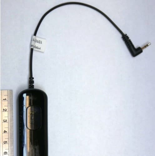
QYPPWR0902
Dec 08, 2013Bluetooth Accessory for Glucose Meters
Equipment Class
DSS - Part 15 Spread Spectrum Transmitter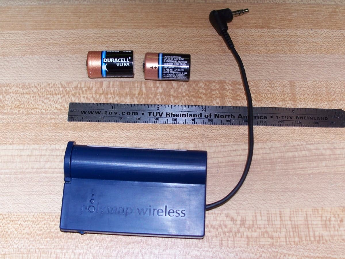
QYPPWR0801
May 08, 2007Bluetooth Remote Unit
Equipment Class
DSS - Part 15 Spread Spectrum Transmitter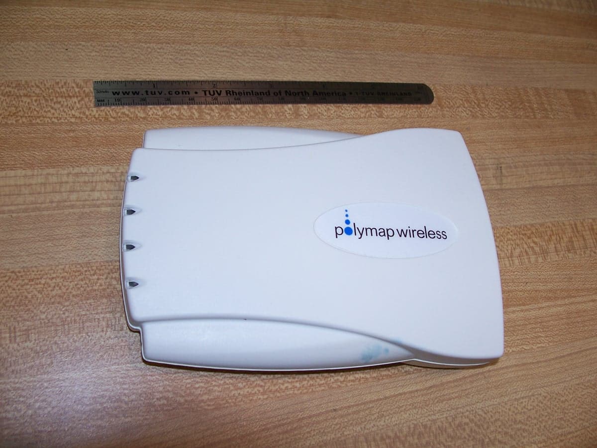
QYPPWA0801
May 08, 2007Bluetooth Access Point
Equipment Class
DSS - Part 15 Spread Spectrum Transmitter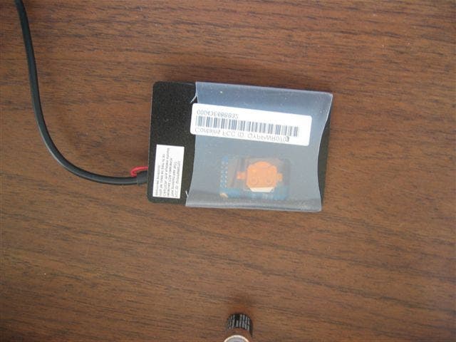
QYPPWR0703
May 26, 2005Bluetooth Remote
Equipment Class
DSS - Part 15 Spread Spectrum Transmitter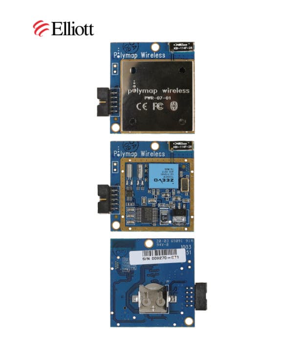
QYPPWR0701
Sep 08, 2003Bluetooth Transceiver
Equipment Class
DSS - Part 15 Spread Spectrum Transmitter