QYPPWR0902Bluetooth Accessory for Glucose Meters
Polymap Wireless LLC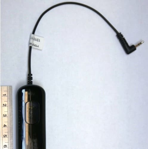
Click to zoom
Application Details
- Equipment Class
- DSS - Part 15 Spread Spectrum Transmitter
- Date of Grant
- Dec 08, 2013
- Application Purpose
- Original Equipment
- Date of Application
- Dec 08, 2013
- Equipment Note
- Bluetooth Accessory for Glucose Meters
- Frequency Range
- 2402.00000000 - 2480.00000000
- Company
- Polymap Wireless LLC
- Country
- United States
Documents & Files
Document Text
Text extracted from the exhibit documents filed with the FCC. Open a document above to read the original.
Users Manual
Polytel ® GMA2 9-2520-A September 2013 1 Polytel ® GMA2 TM Glucose Meter Accessory Model PWR-09-02 USER MANUAL Version: A 310 S. Williams Blvd. Ste. 230 Tucson, Arizona 85711 +1 (520) 747-1811 Mon-Fri 9AM-5PM MST www.polymapwireless.com Polytel ® GMA2 9-2520-A September 2013 2 Polytel ® GMA2 9-2520-A September 2013 3 Contents 1. Introduction ...................................................4 1.1 Overview......................................................................4 1.2 Who is this for? ............................................................5 1.3 Confi gurations ............................................................5 ..........................................................................................6 2 Parts of the GMA ..........................................6 2.1 Visual indicators .........................................................7 2.2 Battery Compartment .................................................9 2.3 Size of your GMA........................................................9 3 Operating Instructions ..................................9 3.1 Changing the batteries ...............................................9 3.2 Connecting the devices ............................................ 11 3.3 Placement of the GMA and receiving station............13 3.4 How to use your GMA...............................................14 3.5 If the data was not sent ............................................18 3.6 Disconnected glucose meter ....................................18 3.7 When You’re Traveling..............................................19 4 Safety Information ......................................20 4.1 Patient Safety ...........................................................20 4.2 Electrical Safety ........................................................21 4.3 Compliance Information............................................22 4.4 About the label at the bottom of the GMA .................23 5 Operator Maintenance ................................23 5.1 Periodic Maintenance ...............................................23 5.2 Cleaning your GMA .................................................24 6 Technical Specifi cations .............................24 6.1 Batteries ...................................................................24 6.2 Temperatures ............................................................25 6.3 Compatibility with other electrical medical equipment 25 6.4 System Availability ....................................................26 7 Trademarks.................................................26 Polytel ® GMA2 9-2520-A September 2013 4 Polytel ® GMA2 9-2520-A September 2013 5 1. Introduction 1.1 Overview Welcome to the world of wireless medical monitoring. In this pamphlet, you will learn how to use and maintain your Polytel® GMA Glucose Meter Accessory. The GMA is an easy-to-use accessory that lets you send the glucose readings you take with your glucose meter wirelessly to a receiving station. No more worrying about writing down the test results and carrying them in to your doctor every visit—it is all done automatically in your own home. There are three parts to sending your readings wirelessly: • You measure your glucose on the LifeScan glucose meter. • The GMA receives the reading from the meter and sends it wirelessly to the receiving station. • The receiving station receives, stores, and sends your readings to your service provider – usually your doctor’s offi ce or a monitoring service. The station is a separate device that is either a self-contained box, called an “ access point,” or your personal computer, cell phone, or handheld computer provided by your monitoring service. Your monitoring service can explain how to use the receiving station. To use the GMA, all you have to do is take the reading using LifeScan meter as usual. Everything else is done automatically for you. To make sure all data is sent to your provider, if the GMA is unable to fi nd a receiving station, it will save the reading along with the date and time you took it. The old reading will be sent along with the next reading. 1.2 Who is this for? The GMA is intended for diabetic patients who want to monitor their glucose levels remotely. It can be used by patients in their homes and in their daily lives. 1.3 Confi gurations The GMA is available in three different confi gurations, which determine which glucose meters are supported. Confi gurations are selected by inserting the proper cable into the GMA: Cable must be fi rmly inserted until fl ush. Polytel ® GMA2 9-2520-A September 2013 6 Polytel ® GMA2 9-2520-A September 2013 7 • PWR-09-02-L for LifeScan meters: OneTouch ® Ultra ® OneTouch ® Ultra2 ® OneTouch ® UltraMini ® OneTouch ® UltraEasy ® OneTouch ® Select™ OneTouch ® Basic™ • PWR-09-02-B for Bayer meters: Contour ® Contour ® TS Contour ® XT Contour ® NEXT Breeze2 • PWR-09-02-A for Abbott meters: FreeStyle ® Lite FreeStyle ® Freedom® Lite 2 Parts of the GMA Your GMA is easy to maintain, set up and use. The most important part to pay attention to is the red light at the bottom right edge of the device. Different blinking patterns tell you when the GMA is sending data, whether it was sent successfully or not, and when it is time to change the batteries. 2.1 Visual indicators The GMA has small blue and red indicator lights in the pushbutton that blink in different patterns when it is doing different things. Figure 1: Indicator light indicates status of the GMA. It may appear as blue or red, depending (see next page). Polytel ® GMA2 9-2520-A September 2013 8 Polytel ® GMA2 9-2520-A September 2013 9 Here are the possible light patterns and their meanings: Light looks likeSpeed/Length It means... Blue on (no blinking) Up to 60 seconds GMA is getting data from glucose meter Blue blinking1 blink per second GMA connecting to receiver. Please wait. Blue, very fast blinking 2 blinks per second for 1-2 seconds GMA sending data to receiving station Blue, Slow b…
Text truncated - open the document above for the full version.
Cover Letter(s)
October 7,2013 Date: October 1,2013 American Certification Body, Inc. 6731 Whittier Avenue Suite C110 McLean, VA 22101 To Whom lt May Concern: SGS is authorized to act on our behalf, until Certification Body, Inc. (ACB). We certify that we are not subject to denial of pursuant to Section 5301 of the Anti-Drug A party, as defined in 47 CFR 1.2002 (b), to benefits, that includes FCC benefits. Thank you, Title: President On behalf of: Polymap Wireless Telephone: +1 (520) 1'47-l1tl pSlym lt wireless 310 S. Williams Btvd. Suite 230 Tucson, AZ 857i 1 l: 520.747.1811 Ii520.747.9408 www.potymap.net notified, for applications to American |eral benefits, that includes FCC benefits, ,Act of 1988, 21 U.S.C. 962. Further, no application is subject to denial of federal Pierre Landau. Ph.D.
Cover Letter(s)
t 310 S. Williams Blvd. O1 . Suite230 f,) llynrap wi reless i;?:,riliii' | - J -l- www.prlrymap.ner December 4,2013 subject: confidentiality Request for:. FCC tD: eyppwR0902. tO:4552A-pwFt0902 Pursuant to FCC 47 CRF 0.457(d) arrd 0.459 and lC RSP-100, Section 10, the applicant requests that a part of the subject FCC applicatbn be heldl confidential. Type of Confidentiality Requested ! Snortterm I Permarnent n Short term flsnortterm ! Permanent" n Snortterm X Permarnent E Snonterm I Permalnent ! Snonterm I permarnent ! Snortterm I Permalnent n Snort term Test Setup photos n Snortterm ! Permanent* Useis Manual *Note: (lnsert Explanation aslJecessaryr) Polymap Wireless. LLC has spent substantial effort in developing this product and it is one of the first of its kind in industry. Having the subject information easily availlable to "competition', would negate the advantage they have achieved by de'veloping this product. Not protecting the details of the design will result in financial hardsihip. Permanent Confidentiality: t exhibits listed abo've as permanently c;onfidential be permanenfly p ue to materials that contain trade secrets and proprietary information ly e pubtic, Short-Term Confidentiality: The applicant requests the exhibits selected abrove as short term c<lnfidential be rruithheld from public view for a period of N/A days from the date of the Grant of Eiquipment Authorization and >rnature release of sensitive infomation prior to mafteting or Applicant is also aware that threy are responrsibte to notify rg the product or the product is nrade availabb to the publii. ; listed above for public disclosure pursuant b FCC public NOTE for lndustry Canada Applications: The applicant understands that until such time that lC distinguishes; between Short Term and Permanent Confidentiality, either typer of marked exhibit above will sinrply be marke<t Confidential when submitted to lC. Exhibit Block Diagrams ExtemalPhotos lntemal Photos Operation DescriptiorVTheory of Operation Parts List & PlacemenVBOM Tune-Up Procedure Schematics Sincerely, By: PaEs r$r-1r.iq- T t,Eceae r+-r,J\jtu, pn.\ (Prinllname) (Signature/Title)
Cover Letter(s)
2.4 GHz WLAN, Home RF, Bluetooth Antenna, 802.11 b/g P/N 2450AT43B100 With Ground Clearance Requirements Minimized Detail Specification: Page 1 of 4 Part Number Frequency Range Peak Gain Average Gain Return Loss ±± ±± ±± ±± ±± Johanson Technology, Inc. reserves the right to make design changes without notice. All sales are subject to Johanson Technology, Inc. terms and conditions. www.johansontechnology.com 4001 Calle Tecate • Camarillo, CA 93012 • TEL 805.389.1166 FAX 805.389.1821 2013 Johanson Technology, Inc. All Rights Reserved 1 2 3 4 Feed Point NC a In 0.008 0.008 0.008 0.008 L W L1 W1 T 0.102 0.020 0.079 Suffix = None 2450AT43B100-EB1SMA (comes with SMA connector) Terminal Configuration No.Function Reel Quanity Operating Temperature 0.020 +.004/-.008 0.012 Part Number Explanation 7.00 2.00 2.60 0.50 Mechanical Dimensions mm 0.20 0.20 P/N Suffix NC "High Frequency Ceramic Solutions" -40 to +85°C 1,000 2450AT43B100 9.5 dB min. -0.5 dBi typ. (XZ-V) 1.3 dBi typ. (XZ-V) 2400 - 2500 Mhz50 Ω 2W max. +5 to +35°C, Humidity: 45- 75%RH, 18 mos. Max 1/29/2013 Input Power Recommended Storage Conditions (for unused product on T&R) General Specifications Impedance Ver 1.1 2.00 0.50 0.20 0.20 0.30 +0.1/-0.2 NC Packaging Style Tin / Lead 100% Tin 0.276 0.079 T & R Bulk Termination Style Evalaution Board Eg. 2450AT43B100S Eg. 2450AT43B100E Eg. 2450AT43B100(E or S) Please consult Factory Suffix = S Suffix = E a T L1 W1 L W 1 2 3 4 2.4 GHz WLAN, Home RF, Bluetooth Antenna, 802.11 b/g P/N 2450AT43B100 With Ground Clearance Requirements Minimized Page 2 of 4 Detail Specification: Mount these devices with brown mark facing up. Units: mm *Antenna feed line width should be designed to provide 50 Ω impedance otherwise improper operation will occur Note 1: Pins 3 & 4, although "NC", must be soldered to its PCB pads for proper electrical operation With Matching Circuits www.johansontechnology.com 4001 Calle Tecate • Camarillo, CA 93012 • TEL 805.389.1166 FAX 805.389.1821 2013 Johanson Technology, Inc. All Rights Reserved "High Frequency Ceramic Solutions" 1/29/2013 Ver 1.1 Note 2: It is recommended that the designer leave available slots for a "pi" (or shunt-series-shunt) network. The antenna matching network values above are used when antenna is monted on Johanson's evaluation board. The matching values on clinet's PCB will be different. Go to: http://johansontechnology.com/tuning and see how to obtain the new values. If you need further help, contact our RF Applications Eng Team at: http://www.johansontechnology.com/en/ask-a-technical-question.html Mounting and Layout Guidelines: JTI P/N for Matching Circuit: Inductor (2.2nH): L-07C2N2SV6T Inductor (2.7nH): L-07C2N7SV6T (Matching circuit and component values will be different, depending on PCB layout) 0.83 2.8 1 1.6 1.6 1 0.8 1.83 0.8 1 2 2 2 10 4.87 2.7 nH 2.2 nH 2.4 GHz WLAN, Home RF, Bluetooth Antenna, 802.11 b/g P/N 2450AT43B100 With Ground Clearance Requirements Minimized Page 3 of 4 Detail Specification: Test Board used orderable p/n: 2450AT43B100-EB1SMA (comes with SMA connector) Re co Return Loss With Matching Circuit Johanson Technology, Inc. reserves the right to make design changes without notice. All sales are subject to Johanson Technology, Inc. terms and conditions. www.johansontechnology.com 4001 Calle Tecate • Camarillo, CA 93012 • TEL 805.389.1166 FAX 805.389.1821 2013 Johanson Technology, Inc. All Rights Reserved "High Frequency Ceramic Solutions" 1/29/2013 Ver 1.1 Typical Electrical Characteristics (T=25 o C) ) ) ) ) ) ) ) ) ) 4.87 40 20 Ground No Ground 10 Antenna 2.4 GHz WLAN, Home RF, Bluetooth Antenna, 802.11 b/g P/N 2450AT43B100 With Ground Clearance Requirements Minimized Page 4 of 4 Detail Specification: Johanson Technology, Inc. reserves the right to make design changes without notice. All sales are subject to Johanson Technology, Inc. terms and conditions. www.johansontechnology.com 4001 Calle Tecate • Camarillo, CA 93012 • TEL 805.389.1166 FAX 805.389.1821 2013 Johanson Technology, Inc. All Rights Reserved "High Frequency Ceramic Solutions" 1/29/2013 Ver 1.1 Typical Electrical Characteristics/Radiation Patterns (T=25 o C) ) ) ) ) ) ) ) ) ) XZ cut @2.45GHz Vertical Horizontal XY cut @2.45GHz Vertical Horizontal YZ cut @2.45GHz Vertical Horizontal Z XY-V/XY-H 180° 270° 0° 90° X Y XY-cut scanning direction XZ-V/XZ-H 180° 270° 0° 90° X Z Y XZ-cut scanning direction YZ-V/YZ-H 180° 270° 0° 90° Z Y YZ-cut scanning direction X
Test Report
Test Report Number: 3322503EMC01 Rev: 1 Polymap Wireless LLC / PWR-09-02 Page: 1 of 55 Remarks: This report details the results of the testing carried out on one sample, the results contained in this test report do not relate to other samples of the same product. The manufacturer should ensure that all products in series production are in conformity with the product sample detailed in this report. This report may only be reproduced and distributed in full. If the product in this report is used in any configuration other than that detailed in the report, the manufacturer must ensure the new system complies with all relevant standards. Any mention of SGS International Electrical Approvals or Testing done by SGS International Electrical Approvals in connection with distribution or use of the product described in this report must be approved by SGS international Electrical Approvals in writing. EMC Test Report Project Number: 3322503 Report Number: 3322503EMC01 Revision Level: 1 Client: Polymap Wireless LLC Equipment Under Test: Glucose Meter Accessory (GMA) Model: PWR-09-02 Applicable Standards: FCC Part 15 Subpart C, § 15.247 RSS-210, Issue 8, December 2010 ANSI C63.10: 2009 Report issued on: 05 DEC 2013 Test Result: Compliant Tested by: Jeremy O. Pickens, Senior EMC Engineer Reviewed by: David Schramm, EMC Manager Test Report Number: 3322503EMC01 Rev: 1 Polymap Wireless LLC / PWR-09-02 Page: 2 of 55 SGS North America Inc. Consumer Testing Services 620 Old Peachtree Road NW, Suite 100, Suwanee, GA 30024 t (770) 570-1800 www.us.sgs.com/cts Member of the SGS Group (SGS SA) Table of Contents 1 SUMMARY OF TEST RESULTS ................................................................................................................................................. 4 1.1 MODIFICATIONS REQUIRED FOR COMPLIANCE .......................................................................................................................... 4 2 GENERAL INFORMATION ........................................................................................................................................................ 5 2.1 CLIENT INFORMATION ............................................................................................................................................................... 5 2.2 TEST LABORATORY ................................................................................................................................................................... 5 2.3 GENERAL INFORMATION OF EUT .............................................................................................................................................. 5 2.4 EUT CONNECTION BLOCK DIAGRAM ....................................................................................................................................... 6 2.5 SYSTEM CONFIGURATIONS ........................................................................................................................................................ 6 2.6 CABLE LIST ............................................................................................................................................................................... 6 3 OCCUPIED BANDWIDTH ........................................................................................................................................................... 7 3.1 TEST RESULT ............................................................................................................................................................................ 7 3.2 TEST METHOD ........................................................................................................................................................................... 7 3.3 TEST SITE .................................................................................................................................................................................. 7 3.4 TEST EQUIPMENT ...................................................................................................................................................................... 7 3.5 TEST SETUP PHOTOGRAPHS ...................................................................................................................................................... 7 3.6 TEST DATA................................................................................................................................................................................ 8 4 PEAK OUTPUT POWER ............................................................................................................................................................ 10 4.1 TEST RESULT .......................................................................................................................................................................... 10 4.2 TEST METHOD ......................................................................................................................................................................... 10 4.3 TEST SITE ................................................................................................................................................................................ 10 4.4 TEST EQUIPMENT .................................................................................................................................................................... 10 4.5 TEST SETUP PHOTOGRAPHS .................................................................................................................................................... 10 4.6 TEST DATA.............................................................................................................................................................................. 11 5 CONDUCTED SPURIOUS EMISSIONS ........................................................................................................................…
Text truncated - open the document above for the full version.
Test Report
Duty Cycle Calculations for the PWR-09-02 100ms Plot Pulse Width Date: 6.DEC.2013 08:39:47 Date: 6.DEC.2013 08:41:47 0-20ms – 16 pulses 20-40ms – 16 pulses Date: 6.DEC.2013 08:42:40 Date: 6.DEC.2013 08:43:37 40-60ms – 16 pulses 60-80ms – 16 pulses Date: 6.DEC.2013 08:44:21 Date: 6.DEC.2013 08:45:31 80-100ms – 16 pulses 80 pulses @ 411us = 32.9ms of on time out of 100ms Duty Cycle = 32.9% 20*LOG(1/.329) = -9.7dB Test Equipment: EquipmentModelManufacturerAsset NumberCal Due Date SIGNAL ANALYZERFSV30ROHDE & SCHWARZB08574928-Aug-2014 COAXIAL CABLE1134GOREB09478516-May-2014 POWER SPLITTERZFRSC-183-S+MINI-CIRCUITSB10174324-Sep-2014 BLUETOOTH TESTERCBTROHDE & SCHWARZS/N: 100011CNR Date: 6.DEC.2013 08:45:50
Contact Information
Applicant
Pierre Landau(President)
Test Firm
SGS North America, Inc.David Schramm
Technical Specifications
| # | Rule Parts | Frequency Range | Power Output |
|---|---|---|---|
| 1 | 15C | 2.40 GHz - 2.48 GHz | 130.00 µW |
Other Applications from Polymap Wireless LLC
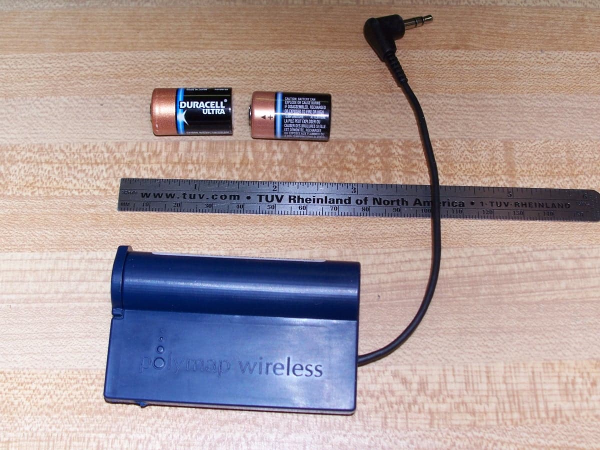
QYPPWR0801
May 08, 2007Bluetooth Remote Unit
Equipment Class
DSS - Part 15 Spread Spectrum Transmitter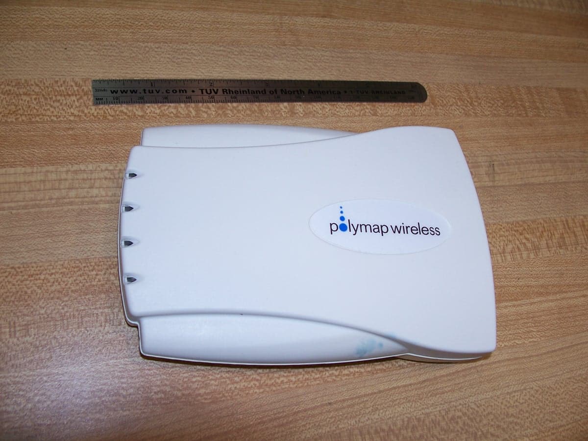
QYPPWA0801
May 08, 2007Bluetooth Access Point
Equipment Class
DSS - Part 15 Spread Spectrum Transmitter
QYPPWR0703
May 26, 2005Bluetooth Remote
Equipment Class
DSS - Part 15 Spread Spectrum Transmitter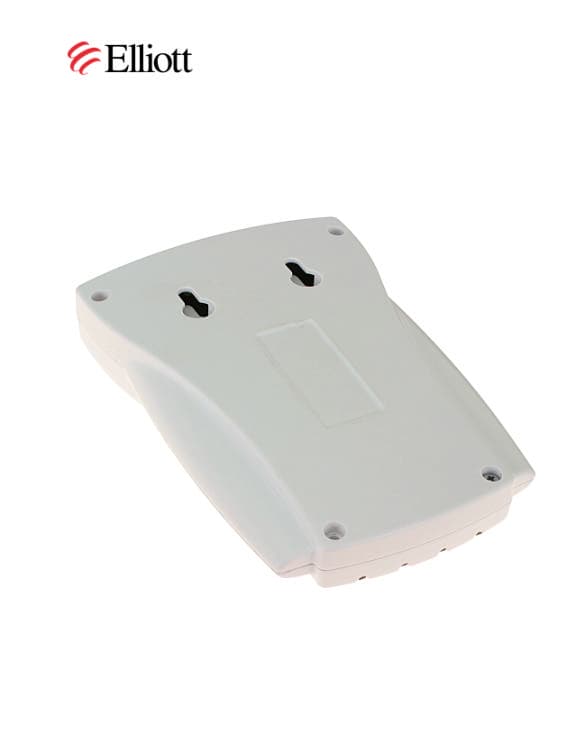
QYPPWA0701
Sep 14, 2003Bluetooth Access Point
Equipment Class
DSS - Part 15 Spread Spectrum Transmitter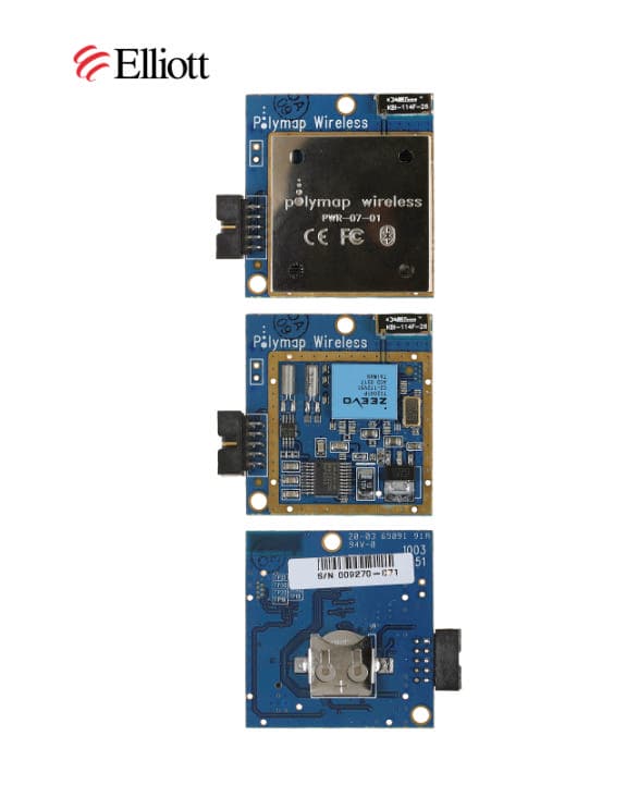
QYPPWR0701
Sep 08, 2003Bluetooth Transceiver
Equipment Class
DSS - Part 15 Spread Spectrum Transmitter