QYPPWR0801Bluetooth Remote Unit
Polymap Wireless LLC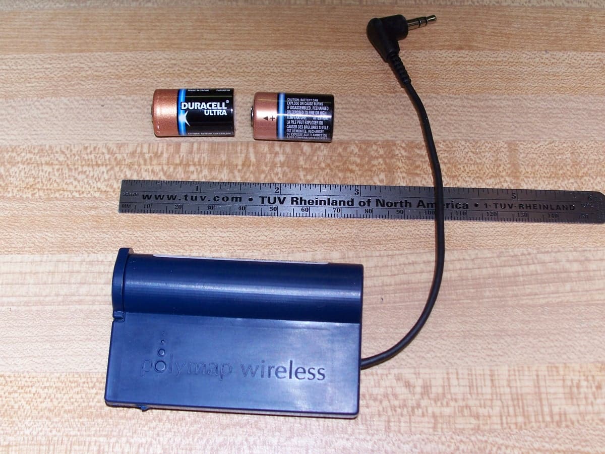
Click to zoom
Application Details
- Equipment Class
- DSS - Part 15 Spread Spectrum Transmitter
- Date of Grant
- May 08, 2007
- Application Purpose
- Original Equipment
- Date of Application
- May 08, 2007
- Equipment Note
- Bluetooth Remote Unit
- Frequency Range
- 2402.00000000 - 2480.00000000
- Company
- Polymap Wireless LLC
- Country
- United States
Documents & Files
Document Text
Text extracted from the exhibit documents filed with the FCC. Open a document above to read the original.
Users Manual
Polytel ® Data Transmission System USER MANUAL Version: R Polymap Wireless 310 S. Williams Blvd. Ste. 346 Tucson, Arizona 85711 Polytel ® Data Transmission System 8-1500-R - 2 - Table of Contents 1 INTRODUCTION......................................................................................................................................... 4 1.1 SYSTEM OVERVIEW................................................................................................................................. 4 1.2 INTENDED USE AND USER........................................................................................................................ 4 2 SYSTEM COMPONENTS AND ACCESSORIES .................................................................................... 4 2.1 PWA-08-01 ACCESS POINT..................................................................................................................... 5 2.2 REMOTE ACCESSORIES............................................................................................................................. 5 2.3 PWR-08-01 REMOTE...............................................................................................................................6 2.4 PWR-08-02 REMOTE...............................................................................................................................6 2.5 PWR-08-03.............................................................................................................................................. 6 3 IDENTIFICATION OF MAJOR PARTS .................................................................................................. 7 4 OPERATING INSTRUCTIONS ................................................................................................................. 9 4.1 INSTALLATION AND SETUP....................................................................................................................... 9 4.2 LOCATION OF DEVICES............................................................................................................................. 9 4.3 A NOTE ON TELEPHONE LINES................................................................................................................ 10 4.4 BATTERIES FOR THE PWR-08-03 ........................................................................................................... 10 4.5 USAGE OF PWA-08-01 ACCESS POINT................................................................................................... 10 4.6 INDICATOR LIGHT ON PWR-08-03 ......................................................................................................... 11 4.7 RETRY SCHEDULE.................................................................................................................................. 11 4.8 OPERATION IN FRANCE, SPAIN OR JAPAN............................................................................................... 11 4.9 TROUBLESHOOTING...............................................................................................................................12 4.9.1 PWA-08-01 Access Point............................................................................................................... 12 4.9.2 PWR-08-03 accessory ................................................................................................................... 13 5 SAFETY INFORMATION ........................................................................................................................ 13 5.1 PATIENT SAFETY.................................................................................................................................... 13 5.2 ELECTRICAL SAFETY.............................................................................................................................. 14 5.3 COMPLIANCE INFORMATION.................................................................................................................. 14 5.3.1 Compliance Requirements............................................................................................................. 14 5.3.2 Compliance Statement ................................................................................................................... 14 5.4 LABEL DEPICTIONS AND LOCATIONS...................................................................................................... 15 5.4.1 Label locations .............................................................................................................................. 15 5.4.2 Nameplate and Symbols ................................................................................................................ 16 6 OPERATOR MAINTENANCE ................................................................................................................ 18 6.1 VISUAL INSPECTION...............................................................................................................................18 6.2 CLEANING YOUR PWA-08-01 AND PWR-08-03: ................................................................................... 18 7 TECHNICAL SPECIFICATIONS ........................................................................................................... 19 7.1 ELECTRICAL INPUT REQUIREMENTS....................................................................................................... 19 7.1.1 PWA-08-01 Access Point............................................................................................................... 19 7.1.2 PWR-08-03 .................................................................................................................................... 19 7.1.3 PWR-08-01 and PWR-08-02 ......................................................................................................... 19 7.2 OPERATING AND STORING YOUR ACCESS POINT AND ACCESSORIES...................................................... 19 CONSULT WITH YOUR LOCAL GARBAGE DISPOSAL …
Text truncated - open the document above for the full version.
Cover Letter(s)
March 13, 2007 To whom it may concern: Polymap Wireless LLC would like to apply for Modular FCC approval for the PWR-08-0x Remote unit. This letter is our application for such according to FCC public notice DA 00-1407. A. In order to be considered a transmitter module, the device must be a complete RF transmitter, i.e., it must have its own reference oscillator (e.g., VCO), antenna, etc. The only connectors to the module, if any, may be power supply and modulation/data inputs. The transmitter is complete with its own reference oscillator and antenna. The only connectors provided are the DC supply, Data, and RF ports. B. Compliance with FCC RF Exposure requirements may, in some instances, limit the output power of a module and/or the final applications in which the approved module may be employed. The radio complies with MPE per 2.1091 for use with mobile or fixed base stations C .While the applicant for a device into which an authorized module is installed is not required to obtain a new authorization for the module, this does not preclude the possibility that some other form of authorization or testing may be required for the device (e.g., a WLAN into which an authorized module is installed must still be authorized as a PC peripheral, subject to the appropriate equipment authorization). The equipment complies with FCC Part 15, SubpartB, Class B – Unintentional Radiators. D. In the case of a modular transceiver, the modular approval policy only applies to the transmitter portion of such devices. Pursuant to Section 15.101(b), the receiver portion will either be subject to Verification, or it will not be subject to any authorization requirements (unless it is a Scanning Receiver, in which case it is also subject to Certification, pursuant to Section 15.101(a)). The receiver operates in the 2.401-2.480 GHz band and complies with FCC Part 15, Subpart B – Radio Receivers. E. The holder of the grant of equipment authorization (Grantee) of the module is responsible for the compliance of the module in its final configuration, provided that the OEM, integrator, and/or end user has complied with all of the instructions provided by the Grantee which indicate installation and/or operating conditions necessary for compliance. End users must conform with the following instructions stated in the users’ manual: • Labeling requirement for equipment using this modular transmitter • RF Exposure information for compliance with FCC Rules 2.1091 or 2.1093 are specified in the user manual for OEM, integrator, and/or end user. 1. The modular transmitter must have its own RF shielding. This is intended to ensure that the module does not have to rely upon the shielding provided by the device into which it is installed in order for all The modular transmitter has its own RF shielding. 310 S. Williams Blvd. Suite 346 Tucson, AZ 85711 t: 520.747.1811 f: 520.747.9408 www.polymap.net z Page 2 March 13, 2007 modular transmitter emissions to comply with Part 15 limits. It is also intended to prevent coupling between the RF circuitry of the module and any wires or circuits in the device into which the module is installed. Such coupling may result in non-compliant operation. 2. The modular transmitter must have buffered modulation/data inputs (if such inputs are provided) to ensure that the module will comply with Part 15 requirements under conditions of excessive data rates or over-modulation. The modular transmitter has buffered data inputs. 3. The modular transmitter must have its own power supply regulation. This is intended to ensure that the module will comply with Part 15 requirements regardless of the design of the power supplying circuitry in the device into which the module is installed. The modular transmitter has its own power supply regulation. 4. The modular transmitter must comply with the antenna requirements of Section 15.203 and 15.204(c). The antenna must either be permanently attached or employ a “unique” antenna coupler (at all connections between the module and the antenna, including the cable). Any antenna used with the module must be approved with the module, either at the time of initial authorization or through a Class II permissive change. The “professional installation” provision of Section 15.203 may not be applied to modules. The radio complies with rules 15.203 and 15.204c. The radio will have a unique antenna coupler (U.FL) for all approved antennas. 5. The modular transmitter must be tested in a stand- alone configuration, i.e., the module must not be inside another device during testing. This is intended to demonstrate that the module is capable of complying with Part 15 emission limits regardless of the device into which it is eventually installed. Unless the transmitter module will be battery powered, it must comply with the AC line conducted requirements found in Section 15.207. AC or DC power lines and data input/output lines connected to the module must not contain ferrites, unless they will be marketed with the module (see Section 15.27(a)). The length of these lines shall be length typical of actual use or, if that length is unknown, at least 10 centimeters to insure that there is no coupling between the case of the module and supporting equipment. Any accessories, peripherals, or support equipment connected to the module during testing shall be unmodified or commercially available (see Section 15.31(i)). The modular transmitter was tested in a stand- alone configuration. 6. The modular transmitter must be labeled with its own FCC ID number, and, if the FCC ID is not visible when the module is installed inside another device, then the outside of the device into which the module is installed must also display a label referring to the The modular transmitter is labeled with its own FCC ID number. The label is fixed on the shield. FCCID: QYPPWR0801 z Page 3 March 13, 2007 enclosed module. This exterior label can use wording such as the following: “Contains Transmitter Module FCC ID: …
Text truncated - open the document above for the full version.
Cover Letter(s)
May 3, 2007 Mark Ryan Senior Engineer TUV Rheinland 762 Park Avenue Youngsville, NC 27596 Dear Mark: The remotes (PWR-08-01, PWR-08-02, PWR-08-03) are three different configurations of the same radio, each intended to communicate with the Access Point over a Bluetooth link. Specifically, they are: • PWR-08-01: Class 1 Bluetooth radio with optional level shifter and onboard antenna • PWR-08-02: Class 1 Bluetooth radio with optional level shifter and external antenna (onboard iPeX connector) • PWR-08-03: Class 1 Bluetooth radio with an onboard antenna and special circuitry for connection to a glucose meter. (Note: This is the unit submitted for testing) The radio sections of all three PWR-08-0x modules are identical ; the PWR-08-03 incorporates additional CMOS switches to disconnect the serial line from the host when the board is powered down, as the host pulls up both RXD and TXD. Sincerely, Pierre Landau, Ph.D. President 310 S. Williams Blvd. Suite 346 Tucson, AZ 85711 t: 520.747.1811 f: 520.747.9408 www.polymap.net
Cover Letter(s)
May 7, 2007 TUV Rheinland of North America 762 Park Avenue Youngsville, NC 27596 RE: Certification Application FCCID: QYPPWR0801 In reference to the application under FCC ID: QYPPWR0801 and pursuant to Sections 0.457(d)(l)(ii) and 0.459 of the Commission’s Rules, the Applicant hereby requests confidential treatment of the accompanying information as outlined below: o Schematics o Block Diagrams o Theory of Operation o PWR-08-0x Family Differences These documents contain detailed system and equipment description and related information about the product that Polymap Wireless considers to be proprietary, confidential, and a custom design and, otherwise, would not release to the general public. Since this design is a basis from which future technological products will evolve, Polymap Wireless considers that this information would be of benefit to its competitors, and that disclosure of the information in these documents would give competitors an unfair advantage in the market Sincerely, Pierre Landau, Ph.D. President 310 S. Williams Blvd. Suite 346 Tucson, AZ 85711 t: 520.747.1811 f: 520.747.9408 www.polymap.net
External Photos
TUV Rheinland FCC ID: QYPPWR0801 762 Park Ave., Youngsville, NC 27596 Tel: (919) 554-3668, Fax: (919) 554-3542 External Photo Exhibit Page 1 of 1 EUT: PWR-08-01 Model: Remote FCC ID: QYPPWR0801 Figure 1 – Overall view of EUT
ID Label/Location Info
TUV Rheinland FCC ID: QYPPWR-08-01 762 Park Ave., Youngsville, NC 27596 Tel: (919) 554-3668, Fax: (919) 554-3542 Label Artwork Page 1 of 1 Label Artwork for PWR-08-01 Label Artwork for PWR-08-02 Label Artwork for PWR-08-03
ID Label/Location Info
TUV Rheinland FCC ID: QYPPWR-08-01 762 Park Ave., Youngsville, NC 27596 Tel: (919) 554-3668, Fax: (919) 554-3542 Label Location Page 1 of 1 Label location on PWR-08-01 Note: early revision of label shown. Label location on PWR-08-02 Note: early revision of label shown. Label location on PWR-08-03 Note: early revision of label shown.
Internal Photos
TUV Rheinland FCC ID: QYPPWR0801 762 Park Ave., Youngsville, NC 27596 Tel: (919) 554-3668, Fax: (919) 554-3542 Internal Photo Exhibit Page 1 of 4 EUT: PWR-08-01 Model: Remote FCC ID: QYPPWR0801 Figure 1 – Overall internal view of EUT - PWR-08-03 with metal shielding removed Note: This was the model of device tested Figure 2 – Overall internal view of PWR-08-03 with metal shielding Notes: 1.This was the model of device tested 2. The RF connector is normally not installed. It was installed in the test sample to allow direct measurements of the transmitter. Antenna External Antenna connector TUV Rheinland FCC ID: QYPPWR0801 762 Park Ave., Youngsville, NC 27596 Tel: (919) 554-3668, Fax: (919) 554-3542 Internal Photo Exhibit Page 2 of 4 EUT: PWR-08-01 Model: Remote FCC ID: QYPPWR0801 Figure 3 – Overall internal view of PWR-08-01/-02 (Identical layout for both) with metal shielding removed Figure 4 – Overall internal view of PWR-08-01/-02 (Identical layout for both) with metal shielding TUV Rheinland FCC ID: QYPPWR0801 762 Park Ave., Youngsville, NC 27596 Tel: (919) 554-3668, Fax: (919) 554-3542 Internal Photo Exhibit Page 3 of 4 EUT: PWR-08-01 Model: Remote FCC ID: QYPPWR0801 Figure 5 – View of PWR-08-01/-02 (Identical layout for both models) Figure 6 – Internal view of PWR-08-03 w/ connector to connect to glucose meter. TUV Rheinland FCC ID: QYPPWR0801 762 Park Ave., Youngsville, NC 27596 Tel: (919) 554-3668, Fax: (919) 554-3542 Internal Photo Exhibit Page 4 of 4 EUT: PWR-08-01 Model: Remote FCC ID: QYPPWR0801 Figure 7 – Internal view of PWR-08-03 with battery connections and data connections to connect to glucose meter. Figure 8 – View of external patch antenna for specific application(s)
Operational Description
Remote unit, FCCID; QYPPWR-08-01 Operational Description Please refer to the schematic, CSR BC212015 data sheet, and block diagram. This unit consists of a Cambridge Silicon Radio (CSR) Bluetooth chip with embedded XAP2 processor. An RF power amplifier and an LNA are used to provide 100m (Bluetooth Class 1) range for the device. A real-time clock with battery backup is connected with GPIO lines. In normal operation, medical data is retrieved from the host device over a serial connection and stored in the flash memory. A wireless connection is established to an access point and the data is forwarded over the link. Access point, FCCID; QYPPWA-08-01 Operational Description Please refer to the schematic, CSR BC212015 data sheet, and block diagram. This device consists of a Philips LPC2292 ARM processor with two serial connections. One serial connection is used to communicate with a Bluetooth module functionally identical to the Remote Unit. The other serial connection is used to communicate with a v.92 telephone modem from Conexant. A real-time clock identical to that in the remote unit is attached to the GPIO lines of the ARM CPU instead of to the Bluetooth chip. In normal operation, the access point listens for medical data coming in over its Bluetooth port, stores that data in flash memory, then dials a number and forwards the data over the telephone modem.
Test Report
Report Number: 30683466.011 Page 1 of 71 EUT: Remote Unit Model: PWR-08-03 EMC / Rev 11/28/2006 FCCID: QYPPWR0801 Emissions Test Report EUT Name: Remote Unit EUT Model: PWR-08-03 FCC Title 47, Part 15, Subpart C, RSS-210 Issue 6 Prepared for: Pierre Landau, Ph.D. Polymap WIreless LLC 310 S. Williams Blvd, Suite 346 Tucson, AZ 85711 Tel: 520-747-1811 Fax: None Prepared by: TUV Rheinland 762 Park Avenue Youngsville, NC 27596 Tel: (919) 554-0901 Fax: (919) 556-2043 http://www.tuv.com/ Report/Issue Date: 3 May 2007 Report Number: 30683466.011 Statement of Compliance Report Number: 30683466.011 Page 2 of 71 EUT: Remote Unit Model: PWR-08-03 EMC / Rev 11/28/2006 Manufacturer: Polymap WIreless LLC 310 S. Williams Blvd, Suite 346 Tucson, AZ 85711 520-747-1811 Requester / Applicant: Pierre Landau, Ph.D. Name of Equipment: Remote Unit Model No. PWR-08-03 Type of Equipment: Intentional Radiator Application of Regulations: FCC Title 47, Part 15, Subpart C, RSS-210 Issue 6 Test Dates: 18 January 2007 to 01 March 2007 Guidance Documents: Emissions: FCC 47 CFR Part 15, RSS-210 Issue 6 Test Methods: Emissions: ANSI C63.4:2005 The electromagnetic compatibility test and documented data described in this report has been performed and recorded by TUV Rheinland, in accordance with the standards and procedures listed herein. As the responsible authorized agent of the EMC laboratory, I hereby declare that a sample of one, of the equipment described above, has been shown to be compliant with the EMC requirements of the stated regulations and standards based on these results. If any special accessories and/or modifications were required for compliance, they are listed in the Executive Summary of this report. This report must not be used to claim product endorsement by NVLAP or any agency of the U.S. Government. This report contains data that are not covered by NVLAP accreditation. This report shall not be reproduced except in full, without the written authorization of the laboratory. 3 May 2007 Test Engineer: Mark Ryan Date Industry Canada 200094-0 90552 and 100881 IC3755 TABLE OF CONTENTS Report Number: 30683466.011 Page 3 of 71 EUT: Remote Unit Model: PWR-08-03 EMC / Rev 11/28/2006 1 EXECUTIVE SUMMARY .................................................................................................................4 1.1 SCOPE............................................................................................................................................4 1.2 PURPOSE........................................................................................................................................4 1.3 SUMMARY OF TEST RESULTS........................................................................................................4 1.4 SPECIAL ACCESSORIES OR EQUIPMENT MODIFICATIONS..............................................................5 2 LABORATORY INFORMATION....................................................................................................5 2.1 ACCREDITATIONS & ENDORSEMENTS...........................................................................................5 2.2 TEST FACILITIES............................................................................................................................6 2.3 MEASUREMENT UNCERTAINTY.....................................................................................................7 2.4 CALIBRATION TRACEABILITY.......................................................................................................7 3 PRODUCT INFORMATION.............................................................................................................8 3.1 PRODUCT DESCRIPTION.................................................................................................................8 3.2 EQUIPMENT CONFIGURATION........................................................................................................9 3.3 OPERATION MODE.........................................................................................................................9 4 EMISSIONS.......................................................................................................................................10 4.1 CHANNEL SEPARATION PART 15.247(A)(1) ................................................................................10 4.2 PSEUDORANDOM HOPPING ALGORITHM FCC PART 15.247(A)(1)..............................................11 4.3 TIME OF OCCUPANCY FCC PART 15.247(A)(1)(III) .....................................................................13 4.4 20DB BANDWIDTH; §15.247(A)(1) ..............................................................................................16 4.5 99% POWER BANDWIDTH; RSS-210 §5.9.1.................................................................................18 4.6 PEAK OUTPUT POWER FCC PART 15.247(B)(1) ..........................................................................22 4.7 MAXIMUM PERMISSIBLE EXPOSURE; FCC §15.247(B)(5), RSS-210 §14....................................24 4.8 BAND-EDGE MEASUREMENT FCC §15.247(D), RSS-210 §6.2.2(O)(E1) ...................................25 4.9 SPURIOUS EMISSIONS; FCC §15.247(C), RSS-210 §6.2.2(Q1) ....................................................28 4.10 FREQUENCY HOPPING SPREAD SPECTRUM SYSTEMS FCC PART 15.247(G)...............................39 4.11 INCORPORATION OF INTELLIGENCE FCC PART 15.247(H) ..........................................................39 4.12 FREQUENCY STABILITY FCC PART 15.215(C) ............................................................................40 4.13 RADIATED EMISSIONS WHEN NOT TRANSMITTING FCC PART 15.109(A) ...................................42 4.14 CONDUCTED EMISSIONS FCC PART 15.107(A) AND 15.207........................................................48 5 TEST EQUIPMENT USE LIST ......................................................................................................53 5.1 TEST EQUIPMENT USED................…
Text truncated - open the document above for the full version.
Test Setup Photos
TUV Rheinland FCC ID: QYPPWR0801 762 Park Ave., Youngsville, NC 27596 Tel: (919) 554-3668, Fax: (919) 554-3542 Internal Photo Exhibit Page 1 of 5 EUT: PWR-08-01 Model: Remote FCC ID: QYPPWR0801 Figure 1 – Radiated emissions test setup (worse case orientation) Computer interface board EUT Figure 2 – Radiated emissions test setup (30MHz – 1GHz) TUV Rheinland FCC ID: QYPPWR0801 762 Park Ave., Youngsville, NC 27596 Tel: (919) 554-3668, Fax: (919) 554-3542 Internal Photo Exhibit Page 2 of 5 EUT: PWR-08-01 Model: Remote FCC ID: QYPPWR0801 Figure 3 – Radiated emissions test setup (1GHz – 18GHz) Figure 4 - Radiated Emissions test setup evaluating the patch-antenna. (Worst case orientation) Note: All three orientations were evaluated TUV Rheinland FCC ID: QYPPWR0801 762 Park Ave., Youngsville, NC 27596 Tel: (919) 554-3668, Fax: (919) 554-3542 Internal Photo Exhibit Page 3 of 5 EUT: PWR-08-01 Model: Remote FCC ID: QYPPWR0801 Figure 5 – Radiated emissions test setup (Investigating 2 nd orientation) Figure 6 – Radiated emissions test setup (Investigating 3 rd orientation) TUV Rheinland FCC ID: QYPPWR0801 762 Park Ave., Youngsville, NC 27596 Tel: (919) 554-3668, Fax: (919) 554-3542 Internal Photo Exhibit Page 4 of 5 EUT: PWR-08-01 Model: Remote FCC ID: QYPPWR0801 Figure 7 – Typical Conducted RF measurements using spectrum analyzer Figure 8 – Extreme Temperature test setup TUV Rheinland FCC ID: QYPPWR0801 762 Park Ave., Youngsville, NC 27596 Tel: (919) 554-3668, Fax: (919) 554-3542 Internal Photo Exhibit Page 5 of 5 EUT: PWR-08-01 Model: Remote FCC ID: QYPPWR0801 Figure 9 – Extreme Temperature test setup Figure 10 – Typical Extreme Voltage test setup RF Probe to Spectrum Anal yzer EUT
Contact Information
Applicant
Pierre Landau(President)
Test Firm
TUV Rheinland of North AmericaMichael Moranha
Technical Specifications
| # | Rule Parts | Frequency Range | Power Output |
|---|---|---|---|
| 1 | 15C | 2.40 GHz - 2.48 GHz | 31.00 mW |
Other Applications from Polymap Wireless LLC
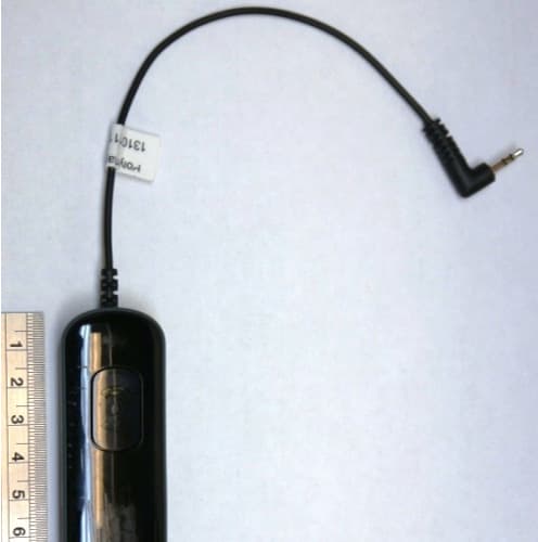
QYPPWR0902
Dec 08, 2013Bluetooth Accessory for Glucose Meters
Equipment Class
DSS - Part 15 Spread Spectrum Transmitter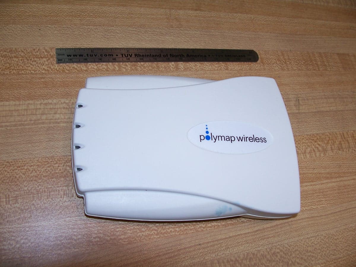
QYPPWA0801
May 08, 2007Bluetooth Access Point
Equipment Class
DSS - Part 15 Spread Spectrum Transmitter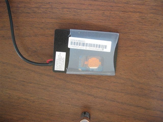
QYPPWR0703
May 26, 2005Bluetooth Remote
Equipment Class
DSS - Part 15 Spread Spectrum Transmitter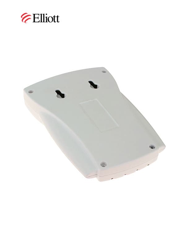
QYPPWA0701
Sep 14, 2003Bluetooth Access Point
Equipment Class
DSS - Part 15 Spread Spectrum Transmitter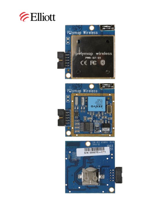
QYPPWR0701
Sep 08, 2003Bluetooth Transceiver
Equipment Class
DSS - Part 15 Spread Spectrum Transmitter