R4GJY-2282.4 GHz Color TFT LCD AV Wireless Monitor
Joyo Electronics Company Limited
Click to zoom
Application Details
- Equipment Class
- DXX - Part 15 Low Power Communication Device Transmitter
- Date of Grant
- Jun 30, 2004
- Application Purpose
- Original Equipment
- Date of Application
- Jun 30, 2004
- Equipment Note
- 2.4 GHz Color TFT LCD AV Wireless Monitor
- Frequency Range
- 2411.00000000 - 2473.00000000
- Country
- Hong Kong
Documents & Files
Document Text
Text extracted from the exhibit documents filed with the FCC. Open a document above to read the original.
Block Diagram
FCC ID: R4GJY-228 ——————————————————————————————————————————————— Advanced Compliance Lab 6 Randolph Way, Hillsborough, NJ 08844 Tel: (908) 927-9288 Fax: (908) 927-0728 14 4. SYSTEM BLOCK DIAGRAM Figure 4.1 System BLOCK DIAGRAM
Cover Letter(s)
Mike Kuo From: [email protected] Sent: June23 2004 Wednesday 12:12 PM To: [email protected] Subject: Re: FW: Joyo Electronics Company Limited, FCC ID: R4GJY-228, Assessm ent NO.... 7/1/2004 In a message dated 6/22/04 10:28:48 PM Eastern Daylight Time, [email protected] writes: Question #1:FCC Docket 01-278, 95-19 and FCC 03-149 has been published in Federal Register on Dec. 09, 2003 with effective date of Jan. 08, 2004. All applications submitted after Jan.08 shall comply with ANSI C63.4:2001 procedures. In the test report, ANSI C63.4:1992 is used. Please confirm the tests were performed per ANSI C63.4:2001 and revised the test report to indicate the test procedure used. Question #2:Per ANSI C63.4:2001, section 13.1.1.1 of procedures, " If device is equipped with input connectors for external modulation, typical modulation signals shall be applied at the max.-rated input level for the device ..". In the test report, there is external modulation applied to produce necessary modulation to simulate the worst case emission. Please redo the tests by following this procedures. Question #3: User Manual does not contain information required per section 15.21 of FCC rules. Please provide revised user manual. Question #4: Only radiated fundamental field strength at channel 4 was included in the test report. Based upon the test report,, the channel 4 is the worst case, please provide radiated spurious emission test data up to 10th harmonics with fundamental frequency tuned at channel 4 per section 15.249 (d) requirements. Best Regards Mike Kuo Hi, Mike. I revised the report (page 6 and 18, 19) and manual according to your questions and the test data. Regards, Wei
External Photos
FCC ID: R4GJY-228 ——————————————————————————————————————————————— Advanced Compliance Lab 6 Randolph Way, Hillsborough, NJ 08844 Tel: (908) 927-9288 Fax: (908) 927-0728 21 Figure 7.1 Top view FCC ID: R4GJY-228 ——————————————————————————————————————————————— Advanced Compliance Lab 6 Randolph Way, Hillsborough, NJ 08844 Tel: (908) 927-9288 Fax: (908) 927-0728 22 Figure 7.2 Bottom view
ID Label/Location Info
FCC ID: R4GJY-228 ——————————————————————————————————————————————— Advanced Compliance Lab 6 Randolph Way, Hillsborough, NJ 08844 Tel: (908) 927-9288 Fax: (908) 927-0728 8 2. PRODUCT LABELING This device complies with part 15 of the FCC Rules. Operating is subject to the following two conditions: (1) This device may not cause harmful interference, and (2) this device must accept any interference received, including interference that may cause undesired operation. Figure 2.1 FCC ID Label Figure 2.2 Location of the Label FCC LABEL FCC ID: R4GJY-228 BOTTOM OF THE CAMERA
Internal Photos
FCC ID: R4GJY-228 ——————————————————————————————————————————————— Advanced Compliance Lab 6 Randolph Way, Hillsborough, NJ 08844 Tel: (908) 927-9288 Fax: (908) 927-0728 23 Figure 7.3 Open view FCC ID: R4GJY-228 ——————————————————————————————————————————————— Advanced Compliance Lab 6 Randolph Way, Hillsborough, NJ 08844 Tel: (908) 927-9288 Fax: (908) 927-0728 24 Figure 7.4 PCB Component Side FCC ID: R4GJY-228 ——————————————————————————————————————————————— Advanced Compliance Lab 6 Randolph Way, Hillsborough, NJ 08844 Tel: (908) 927-9288 Fax: (908) 927-0728 25 Figure 7.5 PCB Foil Side FCC ID: R4GJY-228 ——————————————————————————————————————————————— Advanced Compliance Lab 6 Randolph Way, Hillsborough, NJ 08844 Tel: (908) 927-9288 Fax: (908) 927-0728 26 Figure 7.6 RF Box Open View FCC ID: R4GJY-228 ——————————————————————————————————————————————— Advanced Compliance Lab 6 Randolph Way, Hillsborough, NJ 08844 Tel: (908) 927-9288 Fax: (908) 927-0728 27 Figure 7.7 Camera Open View/Component Side FCC ID: R4GJY-228 ——————————————————————————————————————————————— Advanced Compliance Lab 6 Randolph Way, Hillsborough, NJ 08844 Tel: (908) 927-9288 Fax: (908) 927-0728 28 Figure 7.8 Camera Foil Side
Operational Description
JY228T Operation circuit description 1. Images and audio Operation circuit description (1) External images signal is picked by camera module,these signals are converted into color composite video signal out.Then color composite video signal are sent into TX MODULE by component CON2 (2) Audio signal is picked by microphone, then it is amplified by U2A,then via high-pass filter it is sent into TX MODULE. (3) Audio and video signals are modulated by 2.4G RF signal inTX MODULE. And then amplifier it is can be transmitted 2. Controlling circuit and external interface description (1).S1 is switch of power (2).K2 is switch of night-lamp selection (3)K1 is switch of channal selection. These all have A B C D four channal and A B C D four indication LED . (4) Component Z1.Q5.Q7.LED1 are circuit of low voltage indication.When voltage is ok the GREEN LED of douple LED1 is bright:;When voltage is low the GREEN LED and RED LEDof douple LED1 are all bright,so LED1 spark orange light. (5) Component D2.D3.Q4.Q2 are circuit of audio auto-gain-controlling. (6) Component U2B.U2C.Q6.Q1 are circuit of microphone controlling.When dudio is so low that PIN8 of U2C is low level,so Q6.Q5 are cut ,then U1 .TX MODULE don’t operation. (7) J2 is in port of AC adapater 3 Power supply circuit description (1) Component U1 is circuit of 5V voltagr regaulator (2) Component R3.Z2 are circuit of 5V voltagr regaulator (3) Component R26.D1 are circuit of battery recharging
Test Report
ELECTROMAGNETIC EMISSION COMPLIANCE REPORT of 2.4GHZ COLOR TFT LCD AV WIRELESS MONITOR TRANSMITTER MODEL: JY-228 FCC ID: R4GJY-228 May 6, 2004 This report concerns (check one): Original grant x Class II change Equipment type: LOW POWER TRANSMITTER Deferred grant requested per 47 CF 0.457(d)(1)(ii)? yes no x If yes, defer until: (date) Company agrees to notify the Commission by (date) of the intended date of announcement of the product so that the grant can be issued on that date. Transition Rules Request per 15.37? yes no x If no, assumed Part 15, Subpart B for unintentional radiators - the new 47 CFR [10-1-90 Edition] provision. Report prepared for: JOYO ELECTRONICS COMPANY LIMITED Report prepared by: Advanced Compliance Laboratory, Inc. Report number: 0048-040503-01-TX The test result in this report IS supported and covered by the NVLAP accreditation 6 Randolph Way Hillsborough, NJ 08844 Tel: (908) 927 9288 Fax: (908) 927 0728 Advanced Com pliance Laboratory FCC ID: R4GJY-228 ——————————————————————————————————————————————— Advanced Compliance Lab 6 Randolph Way, Hillsborough, NJ 08844 Tel: (908) 927-9288 Fax: (908) 927-0728 2 Table of Contents Report Cover Page .........................................................................................................1 Table of Contents ...........................................................................................................2 Figures.............................................................................................................................3 1. GENERAL INFORMATION ...................................................................................4 1.1 Verification of Compliance .........................................................................4 1.2 Equipment Modifications............................................................................5 1.3 Product Information....................................................................................6 1.4 Test Methodology.........................................................................................6 1.5 Test Facility ..................................................................................................6 1.6 Test Equipment ............................................................................................6 1.7 Statement of the Document Use..................................................................7 2. PRODUCT LABELING............................................................................................8 3. SYSTEM TEST CONFIGURATION ......................................................................9 3.1 Justification ..................................................................................................9 3.2 Special Accessories.......................................................................................9 3.3 Configuration of Tested System .................................................................9 4. SYSTEM BLOCK DIAGRAM.................................................................................13 5. CONDUCTED EMISSION DATA ..........................................................................14 5.1 Test Methods and Conditions .....................................................................14 5.2 Test Data .......................................................................................................14 6. RADIATED EMISSION DATA ...............................................................................17 6.1 Field Strength Calculation ..........................................................................17 6.2 Test Methods and Conditions .....................................................................17 6.3 Test Data .......................................................................................................18 7. PHOTOS OF TESTED EUT ....................................................................................19 FCC ID: R4GJY-228 ——————————————————————————————————————————————— Advanced Compliance Lab 6 Randolph Way, Hillsborough, NJ 08844 Tel: (908) 927-9288 Fax: (908) 927-0728 3 Figures Figure 2.1 FCC ID Label...............................................................................................8 Figure 2.2 Location of Label on Back of the EUT ......................................................8 Figure 3.1 Cable Interlink Configuration....................................................................10 Figure 3.2 Radiated Front .............................................................................................11 Figure 3.3 Radiated Rear ..............................................................................................11 Figure 3.4 Conducted Front..........................................................................................12 Figure 3.5 Conducted Rear ...........................................................................................12 Figure 4.1 EUT BLOCK DIAGRAM...........................................................................13 Figure 5.1 Line Conducted............................................................................................14 Figure 5.2 Neutral Conducted ......................................................................................15 Figure 7.1 Top View.......................................................................................................20 Figure 7.2 Bottom View .................................................................................................21 Figure 7.3 Open View ....................................................................................................22 Figure 7.4 PCB Component Side ..................................................................................23 Figure 7.5 PCB Foil Side ...............................................................................................24 Figure 7.6 RF Box Open View ....................................................................…
Text truncated - open the document above for the full version.
Test Setup Photos
FCC ID: R4GJY-228 ——————————————————————————————————————————————— Advanced Compliance Lab 6 Randolph Way, Hillsborough, NJ 08844 Tel: (908) 927-9288 Fax: (908) 927-0728 11 Figure 3.2 Radiated Front-X Position Figure 3.3 Radiated Front-Y Position FCC ID: R4GJY-228 ——————————————————————————————————————————————— Advanced Compliance Lab 6 Randolph Way, Hillsborough, NJ 08844 Tel: (908) 927-9288 Fax: (908) 927-0728 12 Figure 3.4 Radiated Rear FCC ID: R4GJY-228 ——————————————————————————————————————————————— Advanced Compliance Lab 6 Randolph Way, Hillsborough, NJ 08844 Tel: (908) 927-9288 Fax: (908) 927-0728 13 Figure 3.5 Conducted Front Figure 3.6 Conducted Rear
Contact Information
Applicant
George Lau(Admin)
Test Firm
Advanced Compliance LaboratoryWei Li
Technical Specifications
| # | Rule Parts | Frequency Range | Power Output |
|---|---|---|---|
| 1 | 15C | 2.41 GHz - 2.47 GHz | - |
Other Applications from Joyo Electronics Company Limited
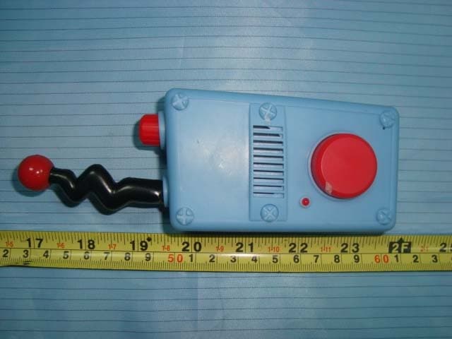
R4G20106M6001
Aug 25, 2010P&F Walkie Talkie
Equipment Class
FRF - Part 95 Family Radio Face Held Transmitter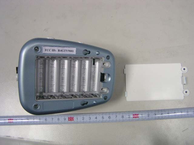
R4GTV9001
Jan 14, 2007Wireless Baby Monitor
Equipment Class
DXX - Part 15 Low Power Communication Device Transmitter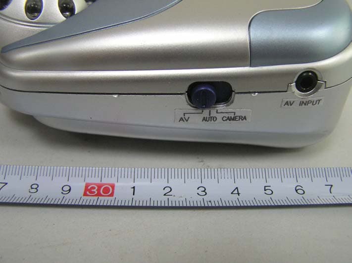
R4GJY238T01
Feb 08, 2006Wireless Baby Monitor
Equipment Class
DXX - Part 15 Low Power Communication Device Transmitter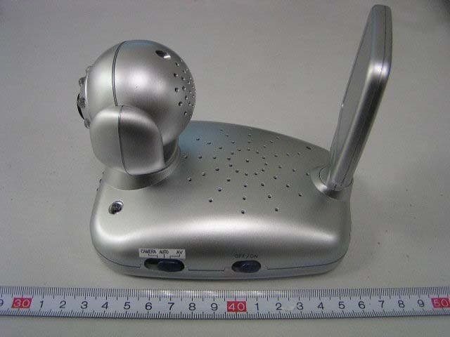
R4GJY278T01
Jan 18, 2006Wireless Baby Monitor
Equipment Class
DXX - Part 15 Low Power Communication Device Transmitter
R4GJY16601
Oct 02, 2005Wireless Baby Monitor
Equipment Class
DXX - Part 15 Low Power Communication Device Transmitter