R4GJY16601Wireless Baby Monitor
Joyo Electronics Company Limited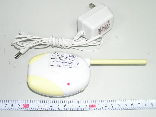
Click to zoom
Application Details
- Equipment Class
- DXX - Part 15 Low Power Communication Device Transmitter
- Date of Grant
- Oct 02, 2005
- Application Purpose
- Original Equipment
- Date of Application
- Oct 02, 2005
- Equipment Note
- Wireless Baby Monitor
- Frequency Range
- 49.83000000 - 49.87500000
- Country
- Hong Kong
Documents & Files
Document Text
Text extracted from the exhibit documents filed with the FCC. Open a document above to read the original.
Users Manual
Operating Instruction INTRODUCTION We are pleased you decided to purchase this JY-166 Mobile Baby monitor that enables you to monitor your child from wherever you are in and around your house. Both of the transmitter and receiver are operated by battery or with external AC adaptor. Both units are fitted with a belt-clip that designed to clip onto a belt or clothing, or wall mounting. The built-in microphone of the transmitter will pick up your baby’s sounds and transmit them to the portable receiver that remains with you. The receiver also features an LED sound bar that provides additional security by making sound visible with lights should you be prevented from hearing the transmission. Since the communication is wireless, it is possible that similar units in your neighborhood can receive your sound or you receive signal from other appliances. There are two channels, which allow the system works properly without interference. Switch in such event both your stations to the other channel. CAUTION PLEASE READ ALL THE INSTRUCTIONS VERY CAREFULLY BEFORE USING THIS MONITOR. THE BABYSITTER IS NOT INTENDED TO REPLACE ADULT SUPERVISION OF CHILDREN. • Replace only with the same or equivalent type of batteries recommended by the manufacturer. • Please dispose of old, defective batteries in an environmentally friendly manner in accordance with the relevant legislation. • No naked flames sources, such as lighted candles, should be placed on the apparatus. • The unit shall not be exposed to dripping or splashing and that no objects filled with liquids, such as vases, shall be placed on the unit. • For indoor use, or do not expose to rain. • Use the appliance only in the described manner • Children don’t recognize the risks of electrical appliances. Therefore use or keep the appliance only under supervision of adults and out of reach from children. SETTING UP COMPONENTS The Transmitter • The transmitter can be battery operated when portable unit is required. However, use of external AC adaptor is recommended for prolongs use. • The transmitter can be clipped onto a belt or mounted on wall with the belt-clip. • Place the transmitter at a convenient location that should not more than 2 meters from the baby for optimum voice detection. • Switch on the transmitter by tuning the ON/OFF channels switch to the channel A or B position. The red power light should be ON. • Select the channel for transmission. Transmitter will pick up baby’s sounds automatically and transmit it to receiver immediately. • VOX (Voice Activation) can be turned ON, and the sensitivity can be adjusted by rotating the switch on the transmitter. • Turn OFF the VOX function by rotating the switch towards the OFF sign until a click sound is heard. The transm itter will transmit continuously. How to insert battery Open the battery compartment and insert one 9 volts battery according to the polarity. Always remove the battery when the unit is not being used. To use with mains power Insert the adaptor plug into the DC jack on the side of transmitter and/or receiver. Then plug the adaptor into the main socket. Trouble-shooting • If the transmitter is placed too far away from the receiver, sound disturbances could occur or transmission could be terminated. In this case, move them closer together. • If the receiver placed too close to the transmitter, a whistling sound (acoustic feedback) could occur. In this case, increase the distance between them or decrease the volume. • Continuous background noise from the receiver could mean that the batteries no longer have sufficient capacity and should be changed. . Warning Changes or modifications to this unit not e xpressly approved by the party responsible for compliance will void the user’s authority to operate the equipment. Any change to the equipment will void FCC grant. This equipment has been tested and found to comply with the limits for a Class C digital device, pursuant to part 15 of the FCC Rules. These limits are designed to provide reasonable protection against harmful interference in a residential installation. This equipment generates, uses and can radiate radio frequency energy and, if not installed and used in accordance with the instructions, may cause harmful interference to radio communications. However, there is no guarantee that interference will not occur in a particular installation. If this equipment does cause harmful interference to radio or television reception, which can be determined by turning the equipment off and on, the user is encouraged to try to correct the interference by one or more of the following measures: --Reorient or relocate the receiving antenna. --Increase the separation between the equipment and receiver. --Connect the equipment into an outlet on a circuit different from that to which the receiver is connected. --Consult the dealer or an experienced radio/TV technician for help. This device complies with Part 15 of the FCC Rules. Operation is subject to the following two conditions: (1) this device may not cause harmful interference, and (2) this device must accept any interference received, including interference that may cause undesired operation. Technical Specifications No. of Channels: 2 Power Supply: 1 x 9V battery for both transmitter and receiver; or 9V AC/DC adaptor. Frequencies: Channel A: 49.83Mhz and Channel B: 49.875Mhz. WIRELESS BABY MONITOR JY-166
Block Diagram
JY-166T UNIT CIRCUIT BLOCK DIAGRAM MIC1 ANT 49.830/49.875MHz 9C DC SUPPLY 9v Battery or ACadaptor AUDIO AGC R6,D1,D4,Q3,Q2 5V REGULATOR 78L05 Modulate & Osallator Q5,D5,K1B,Y1(16.610MHz)&Y2(16.625MHz),c32,c33. AUDIO AMP U1A ,R5 3-BOUBLEFREQ (49.830/49.875MHz) Q6,R25,T1 OUTPUT,CIRCUIT L3,L4,L6,C26,C27,C29 Micphone senstivity U1B,U1D,VR1,Q4,Q1 49.830/49.875MHz RFAMP R27,Q7,L2,Q8
External Photos
External Photos
ID Label/Location Info
ID Label Label
Internal Photos
Internal Photos EUT-Uncovered View EUT-PCB Top View EUT- PCB Bottom View
Operational Description
JY-166T CIRCUIT DESCRIPTIONS TX UNIT 1 、 9V DC supply, switch on/off by K1, when K1 is at “ON” position,D2 of power LED is bright, 78L05 is 5V regulator, 5V supply to micphone amplfier circuit 、 micphone sensitivity and temperature MODULE 2、 Audio input from MIC,U1A is a audio amplifier. 3 、 Audio AGC circuit :D1,D4,C35,Q3,Q2. 4、Micphone sensitivity circuit: U1B,U1D,VR1,Q4,Q1 are important component, when VR1 is at “OFF’’ position, pin 14 of U1D is high voltage ,Q4,Q1 is pass, 5V voltage is supplied to RF circuit ,TX always work;when VR1 is at “ON’’ position, Micphone sensitivity is adjustable by rotated VOLUME of VR1,if voltage of pin 12 of U1D is lower than pin 13 of U1D, Q4.Q1 don’t pass, 5V voltage isn’t supplied to RF circuit ,TX don’t work. 5、Channel selection: When SWITCH K1 is at “A” position, The Y1(16.610MHZ) OSCILLATOR is selected, The carrier wave of 16.610MHZ is production. By 3-double frequency to 49.830MHz and be amplified by Q4 ,Then pass through L3,L4,L5,T2 to ANT and power out ; When SWITCH K1 is at “B” position, It is same as above,.The frequency of transmittion is 49.875MHZ.
Schematics
1 2 3 4 ABCD 4 3 2 1 D CBA Title Number Revision Size A4 Date: 6-Sep-2005 Sheet of File: H:\p-99\JY166\TX\newbaby.ddb Drawn By: R18 150K R16K8 R12 10K R4100K R5 1M5 R17 1M5 R61K R23K9 R11 10K R10 100K R93K9 R13 3K9 R14 6R8 R28 6R8 R27 33K R20 3K9 R23 300K R24 10K C12 102P C4 104P C2103P C3 104P C8 223P C6103P C1 4.7UF C7100UF C9 220UF MIC1 MIC C13 4.7UF C5105P C17 4.7UF D2 LED-R C10 103P R15 68K R29 150K R26 331 C16 104P C33 151P Y1 16.610MHZ Y2 16.625MHZ C20 151P C19 103P C34 27P C23 47P C25 101P C26 27P C21 27P T11093 L21UH L40.82UH C27 101P C28 27P C29 101P L60430 ANT ANTENNA BAT1 9V J1 JACK C24 103P C22 103P 1 23 U1A LM-324 4 56 7 11 U1B LM-324 R19 300K R21 1K R8220K C15 4.7UF C11 223P C14 102P R22 1K R16 3K9 R739K 5V 5V 5V Q6 3904 R25 300K R30 471 C32 101P B1 B2 B3 B4 K1B SW3P2T A1 A2A3A4 K1A SW3P2T IN G OUT U2 78L05 Q5 3904 Q7 33725 Q4 3904 Q3 3904 Q2 3904 Q1 3906 D4 LL4148 D1 LL4148 D3 LL4148 D51S2638 C36 68P 1213 14 U1D LM-324 R3 27K R32 27K R31 331 C38 103P C37 103P JY166T-V41 L3 0.82UH Deqin zheng 1/1 C18 4.7UF C35 VAL C30 103P C31 VAL C39 VAL R33 0 C42 2P C43 VAL R45 NC R44 NC R42 NC R43 NC Q10 NC Z1NC C44 NC C45 NC 1 2 3 K2 SW1P1T LED1 NC R46 NC AC AC Temperature meter/display VR1A 10K VR1B 10K R34 NC 5V MODULE M1 Q8 3904 R35 3K9 R36 2K2 AC R37 2K2
Test Report
Note: The test report is specially limited to the above company and this particular sample only. It may not be duplicated without prior written consent of Bay Area Compliance Lab Corp. (ShenZhen). This report must not be used by the client to claim product certification, approval, or endorsement by NVLAP, NIST or any agency of the US Government. FCC PART 15.235 EMI MEASUREMENT AND TEST REPORT For JOYO Electronics Company Limited Unit D, 13/F., World Tech Centre, 95 How Ming Street, Kwun Tong,, Kowloon, Hong Kong FCC ID: R4GJY16601 September 23, 2005 This Report Concerns: Original Report Equipment Type: Transmitter, Wireless Baby Monitor Test Engineer: Jandy Su Report No.: RSZ05091901 Test Date: September 21, 2005 Reviewed By: Chris Zeng Prepared By: Bay Area Compliance Lab Corp. (ShenZhen) 6/F, the 3rd Phase of WanLi Industrial Building, ShiHua Road, FuTian Free Trade Zone, ShenZhen, Guangdong 518038, P.R.China Tel: 86-755-33320018 Fax: 86-755-33320008 JOYO Electronics Company Limited FCC ID: R4GJY16601 Report # RSZ05091901 Page 2 of 29 FCC PART 15.235 Report TABLE OF CONTENTS GENERAL INFORMATION.......................................................................................................................................3 PRODUCT DESCRIPTION FOR EQUIPMENT UNDER TEST (EUT) ....................................................................................3 OBJECTIVE...................................................................................................................................................................3 RELATED SUBMITTAL(S)/GRANT(S).............................................................................................................................3 TEST METHODOLOGY..................................................................................................................................................3 TEST FACILITY.............................................................................................................................................................3 LOCAL SUPPORT EQUIPMENT LIST AND DETAILS........................................................................................................4 EXTERNAL I/O CABLE.................................................................................................................................................4 SYSTEM TEST CONFIGURATION ..........................................................................................................................5 JUSTIFICATION.............................................................................................................................................................5 EUT EXERCISE SOFTWARE..........................................................................................................................................5 SPECIAL ACCESSORIES.................................................................................................................................................5 EQUIPMENT MODIFICATIONS.......................................................................................................................................5 CONFIGURATION OF TEST SETUP.................................................................................................................................6 BLOCK DIAGRAM OF TEST SETUP................................................................................................................................6 SUMMARY OF TEST RESULTS ...............................................................................................................................7 §15.203 - ANTENNA REQUIREMENT......................................................................................................................8 STANDARD APPLICABLE..............................................................................................................................................8 §15.207(A) - CONDUCTED EMISSION.....................................................................................................................9 MEASUREMENT UNCERTAINTY....................................................................................................................................9 EUT SETUP..................................................................................................................................................................9 EMI TEST RECEIVER SETUP......................................................................................................................................10 TEST EQUIPMENT LIST AND DETAILS.........................................................................................................................10 TEST PROCEDURE......................................................................................................................................................10 TEST RESULTS SUMMARY..........................................................................................................................................10 TEST DATA................................................................................................................................................................11 PLOT(S) OF TEST DATA..............................................................................................................................................12 §15.209(A) §15.235(A) §15.205- RADIATED EMISSION .......................................................................................17 MEASUREMENT UNCERTAINTY..................................................................................................................................17 EUT SETUP................................................................................................................................................................17 EMI TEST RECEIVER SETUP.................................................................................................…
Text truncated - open the document above for the full version.
Test Setup Photos
Test Setup Photos Conducted Emissions-Front View Conducted Emissions-Side View Radiated Emissions-Front View Radiated Emissions-Rear View Radiated Emissions-Stand View Radiated Emissions-Side View Radiated Emissions-Lie View
Contact Information
Applicant
George Lau(Admin)
Test Firm
Bay Area Compliance Laboratory Corp. (Shenzhen)John Chan
Technical Specifications
| # | Rule Parts | Frequency Range | Power Output |
|---|---|---|---|
| 1 | 15C | 49.83 MHz - 49.875 MHz | - |
Other Applications from Joyo Electronics Company Limited
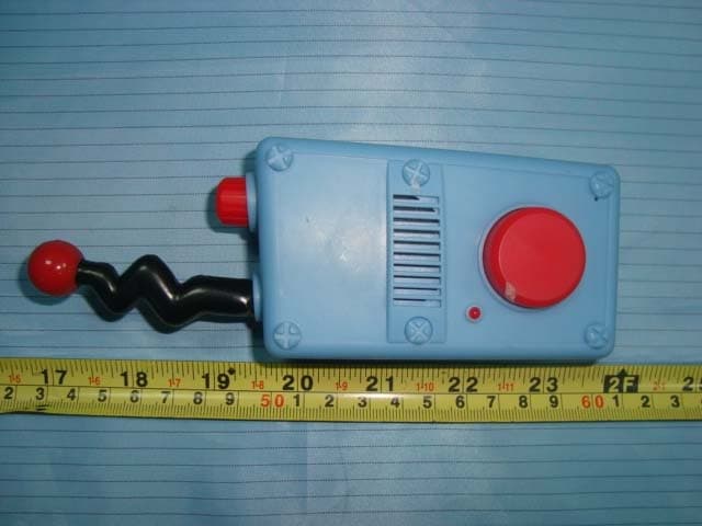
R4G20106M6001
Aug 25, 2010P&F Walkie Talkie
Equipment Class
FRF - Part 95 Family Radio Face Held Transmitter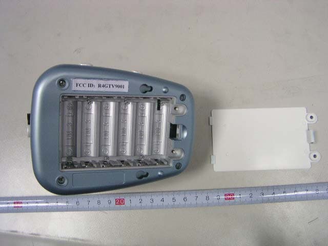
R4GTV9001
Jan 14, 2007Wireless Baby Monitor
Equipment Class
DXX - Part 15 Low Power Communication Device Transmitter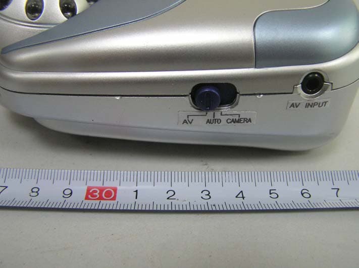
R4GJY238T01
Feb 08, 2006Wireless Baby Monitor
Equipment Class
DXX - Part 15 Low Power Communication Device Transmitter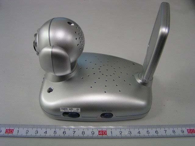
R4GJY278T01
Jan 18, 2006Wireless Baby Monitor
Equipment Class
DXX - Part 15 Low Power Communication Device Transmitter
R4GJY-228
Jun 30, 20042.4 GHz Color TFT LCD AV Wireless Monitor
Equipment Class
DXX - Part 15 Low Power Communication Device Transmitter