R4GJY278T01Wireless Baby Monitor
Joyo Electronics Company Limited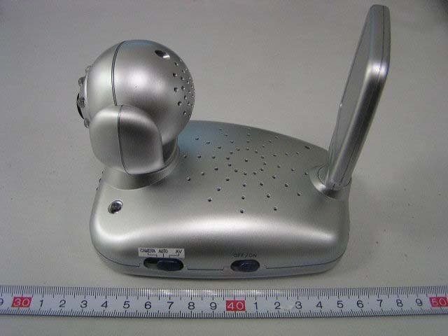
Click to zoom
Application Details
- Equipment Class
- DXX - Part 15 Low Power Communication Device Transmitter
- Date of Grant
- Jan 18, 2006
- Application Purpose
- Original Equipment
- Date of Application
- Jan 18, 2006
- Equipment Note
- Wireless Baby Monitor
- Frequency Range
- 2411.00000000 - 2473.00000000
- Country
- Hong Kong
Documents & Files
Document Text
Text extracted from the exhibit documents filed with the FCC. Open a document above to read the original.
Users Manual
1 TABLE OF CONTENT Page TABLE OF CONTENT INTRODUCTION PACKAGE CONTENT PICTURE OF MONITOR UNIT PICTURE OF CAMEAR UNIT SAFETY INSTRUCTION STATEMENT ON REGULATION 1 2 2 3 4 5 7 INSTALLATION INSTALLATION BATTERY INSTALLATION AC/DC ADAPTOR SPECIAL NOTE FOR JY-229TC MOUNTING THE CAMERARE CHARGING THE UNIT 8 8 8 9 9 10 CAMERA OPERATION POWER ON/OFF CHANNEL SELECTION AUDIO VIDEO INPUT VOICE ACTIVATION AUTOMATIC INFRARED NIGIT VISION 11 11 11 11 11 12 MONITOR OPERATION POWER ON/OFF CHANNEL SLECTION AUTOMATIC CHANNEL SCAN LCD ON/OF FBRIGHTNESS CONTROL AUDIO VIDEO OUTPUT LINK 12 12 12 12 13 13 13 TROUBLE SHOOTING 14 2 INTRODUCTION We are grateful you decided to purchase this 2.4GHz Color LCD A/V Wireless Monitor, which incorporate the latest in advanced technology. We feel strongly that you will be pleased with the quality and features of this product. This 2.4GHz Color LCD A/V Wireless Monitor enables you to transmit picture and sound signals cordlessly, wh ich most ideal for applications such as baby monitoring, hous ehold security, office or warehouse surveillance system, etc. PACKAGE CONTENT Please note that the package should include the follows: a) 1 x Camera Unit b) 1 x Monitor Unit c) 1 x Charging Base Unit (JY-238R only) d) 2 x AC/DC adaptors e) 2 x Audio/Video Cord (1 for JY-229TC) f) This instruction manual Optional Accessories --- Rechargeable Batteries If you find any of the above missing, please contact your retailer. 3 PICTURE OF MONITOR UNIT 1. TFT LCD Display 2. Speaker 3. Power On/Off Indicator 4. Channel Selection Switch 5. Channel indicating LEDs 6. Automatic Channel Scan Indicator 7. Brightness Control (+)(-) 8. Volume and power O/Off switch 9. LCD On/Off Switch 10. DC Jack 11. Audio/Video output 12. Belt Clip 13. Battery Cover (JY-238R) 14. Recharging Base (optional for JY-238R) PICTURE of Monitor Unit 4 PICTURE OF CAMERA UNIT 15. Camera Lens 16. Channel Indicators LEDs 17. Channel Selection Switch 18. Voice Activation Acti on Selection Switch 19. Analog Audio/Video Input Jack 20. Light Sensor for Automatic Night Vision 21. Power On/Off Switch 22. Power On/Off Indicator 23. DC Jack 24. Microphone Picture of Camera Unit 5 SAFETY INSTRUCTION Please observe the following precautions to prevent fire, personal injury, and product damage: Read Instructions: All the safety and operating instructions should be read before the 2.4GHz Color LCD A/V Wireless Monitor is operated. Retain Instructions: The safety and operating instructions s hould be retained for future reference. Heed Warnings: All warnings on the 2.4GHz Color LCD A/V Wireless Monitor and operating instructions should be adhered to. Follow Instructions: All operating instructions should be followed. Water and Moisture: This product is designed for the indoor use only. The unit should not be exposed to dripping or splashing and that no objects filled with liquids, such as vases, shall be placed on the unit. The item should not be used near water; for example, near a bath tub, wash bowl, kitchen sink, laundry tub in a wet basement, of near a swimming pool, etc. Ventilation: The 2.4GHz Color LCD A/V Wireless M onitor should not be situated on a bed, sofa, rug, or similar surface that may block the ventilation openings, or placed in an enclosed installation, such as a bookcase or cabinet that may impede the flow of air thr ough the ventilation openings. Heat: The 2.4GHz Color LCD A/V Monitor should be situated away from heat sources such as radiators, heat regist ers, stoves, or other appliances that produce heat. No naked flames sources, such as lighted candles, should be placed on the apparatus. 6 Power Source: Besides batteries operated, the 2.4 GHz Color LCD A/V Monitor should be connected to a power supply only of the type described in this operating instruction (AC/DC adaptors: 9V 500mA Centre Positive). Cleaning: Use a dry cotton cloth to keep the 2.4GHz Color LCD A/V Monitor free of dust. Do not use water! Non-Use Periods: Always remove the batteries from the Camera and the Monitor battery packs or unplug the AC adaptors from wall ou tlets during long periods of non-use. Object and Liquid Entry: Care should be taken so that objects do not fall into, and liquids are not spilled into the enclosure through the openings. Damage Requiring Services: The 2.4GHz Color LCD A/V Monitor should be serviced by qualified service personnel when: a. Objects have fallen or liquid has been spilled into the products; or b. The units have been exposed to rain; or c. The units do not appear to operat e normally or exhibits a marked change in its performance; or d. The units have been dropped or the enclosure damaged. Caution: a. This product cannot replace responsib le adult supervision of a child. You should personally check your chil d’s activity at regular intervals. b. Never use this 2.4GHz Color LCD A/V Wireless Monitor to a degree where your life or health or the life or health of others or integrity of property depends on its function! Manufacturer will not accept any responsibility or claim for death and injury of any person or lost and damage of any property due to malfunction or misuse of the product. Battery : a. Replace only with the sa me or equivalent type. b. Please dispose of old, defective batt eries in an environmentally friendly manner in accordance with the relevant legislation. 7 STATEMENT ON REGULATION This product is designed to provide reasonable protection against harmful interference in a residential installation. This equipment generate, uses and can radiate radio frequency energy and if not installed and used in accordance with the instructions, may cause harmful interference to radio communications. However, there is no guarantee that interference will not occur in a particular installation. If this equipment does cause harmful interference to radio or television reception, which can be determined by turning the equipment off and on, the user is encouraged to try to correct the interference by one or more of th…
Text truncated - open the document above for the full version.
Block Diagram
JY-278T UNIT CIRCUIT BLOCK DIAGRAM ANT 2.411G 2.433G 2.453G 2.473G 6.0MHz OSCILLATOR(Q8 B1 D3 F1) AUDIO OF MICPHONE AM P AND AGC (IC1C Q9 Q10) 2.411G/2.433G /2.453G/2.473G VCO (D4 Q19) VOX DETECTION CIRCUIT(D1 D2 IC1D Q4 Q6) MCU (IC2) RF AMP (Q21 Q20) PLL SYNTHESIZER (IC3 Q12) EXTERNAL AUDIO SIGNA L DETECTION (JACK2 Q32 Q33 SW2) DATA RECORD (AT24C02) EXTERNAL VIDEOSIGNAL DETECTION(Q29 Q30 Q34 Q31 SW2) VIDEO&INFRARED LED OF CAMERA1 Infrared night-LEDCONTROL CIRCUIT (IC8D Q36) BATTERY RECHARGECIRCUIT(Q24 Q22 IC5 Q23 IC7 POWER SUPPLY ( BAT1 OR EXTERNA L ADAPTER S1) CHANNELSELECTION AND INDICATION(SW1 LED1 LED2 LED3 LED4) LOW POWE R INDICATION (IC1A IC1B Q17 LED5) 5V REGULATER (IC6 Q25 Q13 Q14 Q16 Q26 Q27 Q15)
External Photos
External Photos EUT-Front View EUT-Back View EUT-Left View EUT-Right View
ID Label/Location Info
ID Label Label FCC ID: R4GJY278T01
ID Label/Location Info
ID Label/Location Label Location Information Specifications: Text is Black or white in color and is left justified. Labels are printed in indelible ink on permanent adhesive backing or silk-screened onto the EUT or shall be affixed at a conspicuous location on the EUT. Label Location
Internal Photos
Internal Photos EUT-Inside View (1) EUT-Inside View (2) EUT-Inside View (3) EUT- Main PCB Front View (1) EUT- Main PCB Front View (2) EUT- Main PCB Back View EUT- Antenna PCB Front View EUT- Antenna PCB Back View
Operational Description
JY- 278T circuit of description 1、When battery(or adapter) are inserted properly ,Turn on power switch (S1) in ON position, Led5 of the power indicator lights up green. (if low power, Led5 of the power indicator lights up orange) 2、Channel setting: By pressing button (sw1), 4 channel of A/B/C/D can be selected, and one led of LED1、LED2、LED3、LED4 lights up green,It indicates this channel being set. 3、Signal source selection: 1)、 When switch (SW2) is in “1” position, VIDEO signal only from camera1, AUDIO signal only from micphone. 2)、 When switch (SW2) is in “3” position, external VIDEO& AUDIO signal only external . 3)、When switch (SW2) is in “2” position, Transmitting by VOX.. Only having no voice, external VIDEO& AUDIO signal external can be transmitted: otherwise VIDEO signal from camer1 and AUDIO signal from micphone can be transmitted. 4、AUDIO signal modulation: 1) AUDIO signal from microphone amplified by IC1C or external AUDIO from jack2 can be send into sub-carrier oscillator of 6.0MHZ , 2) the carrying of 6.0Mhz send into VCO and modulated. 5、VIDEO signal modulation: 1)VIDEO signal from camera1 or external jack2 sent into VCO and modulated 6、VCO oscillator circuit : frenquency of VCO selection by pressing SW1, MCU send data of channel into PLL synthesizer (IC3),at the sametime this data will be save by IC4(AT24C02) and then PLL systhesizer (IC3) send signal to VCO, VCO can generate 4 kinds of RF signal (2.411G/2.433G/2.453G/2.473G). 7、RF AMP circuit : RF signal of VCO is amplified by Q20 and Q21, and then transmission out by ANT. 8、Power supply and low power indicate: 1) IC6 regulate 5V voltage, when battery voltage is low , LED5 lights up orange. 9、Battery recharge : Q22、Q24、IC5 、IC7 . 10、Infrared night-led control;In darkness , value of R162 (CDS) enlarge , Voltage of pin 1 of CAMERA1 became low , the LED of infrared in CAMERA1 light up. In daylight value of R162 (CDS) reduce , Voltage of pin 1 of CAMERA1 became high , the LED of infrared in CAMERA1 light out .
Operational Description
JY-278T Technical Speciation DATE:2005-12-17 TRANSMITTER SECTION 1) Frequency: 2411MHz/2433MHz/2453MHz/2473MHz 2) Power Supply: 4*AA BATTERY OR AC Adaptor OUT : 9V/500mA 3) Transmitting power <10dBμV/m (3M) 4) Night Infrared led distance 3-5M 5) Frequency of Sound Subcarrier : 6MHz 6) Video: a) Modulation Type : FM b) Maximum Modulation: 3MHz 7) Audio: a) Modulation Type : FM b) Maximum Modulation: 50kHz 8) Transmitting Current Drain(Infra-red-far led OFF): <180 mA 9) Maximum Operation Current(Infra-red-far led ON): <260mA
Schematics
1 2 3 4 ABCD 4 3 2 1 D CBA Title Number Revision Size A4 Date: 13-Dec-2005 Sheet of File: H:\p-99\ \JY278T\JY278TV1\JY278TAV11.DDB 䗕ḋᵓ Drawn By: C27 47uF R17 472 R18 472 R48 104 R19 105 R51 683 MIC1 C35 472P C36 223P C37 104P C45 224P C46 82P R55 NC R77 123 R49 104 R41 NC R79 332 D2 4148 D1 4148 C48 4.7uF/10V Q10 3904 Q9 3904 R87 153 R40 NC R42 NC R50 104 R43 101 R44 514 D32105C49 22P C50 12P C956P Q8 3904 123 46 B1 2605 R88 102 R91 332 C41 102P C42 102P F1 6MHz R100 331 R89 102 R116 681 R117 101 R126 0R C40 102P 18 916 IC3 SP5655 D4 ISV245 C74 3P C76 0.5P R149 331 Q19 41511 R78 123 R135 0R C78 1.5P Q20 BFG540/X(N43) Q21 BFG540/X(N43) C88 2P R137 47 R142 22 C58 102P C56 102P L115uH C38 104P C61 103P C89 NC C43102P C44 102P C82 10P C77 4P R138 682 R121 222 C57 102P ANT1 C55 102P R136 103 R120 222 C54 102P R139 332 R83103 R127 271 L2 15uH C64105P JY278T-PART1 1.0 1 1 LH.LAN VRF C80 1.5P C75 0.5P RFIN VRF C10 104P R65 104 R104 473 R101 273 R143 154 R66 104 R56 NC Q23906 R57 NC R58 NC R81 NC C51 101P C52 NC C13 104P LV PWC TXC C53 102P C59 102P C63 225P C68 104P C62 18P C29 47uF XT1 4MHz Q12 3904 R32 103 R105 103 R119 222 R33 103 R102 273 C69 103P RFIN VPLL 5V A 10 9 8 IC1CLM324 VOX 1213 14 IC1D LM324 R64 104 SC A C86 NC C47 474P R92 271 R93 102 R134 123 C70 10P C71 4P 5V CLK DATA 14 58 IC4 AT24C02 CSCLK DATA DO 5V C60 102P LED1 LED3 LED2 LED4 R130 471 R128 471 R129 471 R131 471 4VB R82 472 CS DO C81 1.5P C87 1P C79 1.5P C83 NC Q13906 R1223 PWC 5V R30 103 C11 104P C28 47uF R31 103 Q7 PNP1 R29 103 R38 331 R28 303 R39 272 VMOD 4VB R106 473 SW1CH PIN14 C12 104P AMOD C84 NC C85 NC R80 472 TP3 TP2 R34 103 TP1 R52 681 R54 471 R145 473 C72 0.5P C73 0.5P C24 104P R62 222 R46 223 R53 471 Q4NPN Q6PNP R20 472 R23 474 R21 472 R24 153 R25 104 C2 104P C4 103P C5225P C1 105P 4VB PIN14 A Q11 3904 R26 104 R45 152 C23 104P C6NC C7NC R90 NC C8NC VR1 103 P52 1 P53TCCRSTVSSP60P61P62P63 9 P64 10 P65P66P67 VDD OSCO OSCI P50P51 18 IC2EM78P156 R171 472 Q37 3904 R172 104 R173 473 RESET R180 102 R181 102 1 2 3 4 ABCD 4 3 2 1 D CBA Title Number Revision Size A4 Date: 13-Dec-2005 Sheet of File: H:\p-99\ \JY278T\JY278TV1\JY278TBV11.DDB 䗕ḋᵓ Drawn By: 32 1 411 IC1A LM324 56 7IC1B LM324 R76 104 R170 682 R37 103 R112 473 R113 473 R165 683 R97 102 R96 102 C19 104P C22 104P Q17 3904 G R LED5GR 4VB 4VB VDD 4VB C18 104P LV L.H.LAN 2 2 1.0 JY278T-PART2 Q28 UMX1N R11 223 R10 223 CAMERA Q29 UMX1N R103 273 R110 473 R12 223 C93 225P R60 NC R132 471 Q18 3904 R16 223 R114 473 R98 102 R167 221 C94 225P VPLL VPLL VMOD VIDEO Q30 UMX1N Q31 UMX1N R133 471 R144 154 R84 472 C16 104P C17 104P R61 NC R111 473 R156 224 C33 47uF R70 104 R71 104 Q34 3906 Q35 3906 R7223 R85 472 R15 223 R72 104 R73 104 R99 102 R141 332 VOX 1 2 3 4 SW2A SC Q32 UMX1N Q33 UMX1N R115 473 R13 223 R74 104 R75 104 R14 223 R86 223 C20 104P C21 104P D12 4148 D13 4148 VPLL AMOD AMOD AUDIO R125 222 PIN14 4VB 1234 JACK2 JACK-AV AUDIO VIDEO 4VB R166 103 R146 473 R63 222 R160 101 C32 47uF R168 47 D14 4148 D15 4148 R169 332 C3104P C34 47uF Q5NPN R147 473 R148 473 R27 104 C26 104P JACK1 JACK3 D5 FM5817 D6FM5817 D7 FM5817 D8 FM5817 C90 100uF/16V R152 15R* R122 222 Q24 2SA1797 Q22 3904 R2223 56 7 IC5B LM358 R153 224 R4223 R157 304 R108 473 C65 105P 23 84 1 IC5A LM358 IC7 78L05 D94148 R161 514 R68 104 R155 224 R154 224 R67 104 R3 223 C67 105P D10 4148 Q23 3904 R36 103 BAT1 BAT C66 105P D11 4148 R150 5.6 R151 5.6 B C TP4 IC6 5002 C91 100uF/16V C92 100uF C39 104P 5V C15 104P C14 104P VDD TP5 Q25 2SA1797 Q14 3904 Q13 3904 R107 473 R123 222 R94 102 R95 102 R159 NC Q26 2SA1797 Q16 3904 R8223 C30 47uF C31 47uF R124 222 R35 103 VPLL 5VVRF VDD VDD 5V TXC 1 1 234 CAMERA1 CON-4 CAMERA C25 104P R69 104 Q36 NC R140 332 R59 NC 23 84 1 IC8A LM358 VPLL R163 683 R164 683 R109 473 Q27 2SA1797 R9223 Q15 3904 R22 472 VDD R47 223 Q3 3906 R5223 R6223 R118 101 R158 151 C B S1 R162 CDS RESET R174 472 R176 102 R177 102 R175 472 VPLL R178 NC R179 471 C95 102P TP5 TP6 TP7 TP8
Test Report
Note: The test report is specially limited to the above company and this particular sample only. It may not be duplicated without prior written consent of Bay Area Compliance Lab Corp. (ShenZhen). This report must not be used by the client to claim product certification, approval, or endorsement by NVLAP, NIST or any agency of the US Government. FCC PART 15.249 EMI MEASUREMENT AND TEST REPORT For JOYO Electronics Company Limited Unit D, 13/F., World Tech Centre, 95 How Ming Street, Kwun Tong,, Kowloon, Hong Kong FCC ID: R4GJY278T01 January 16, 2006 This Report Concerns: Original Report Equipment Type: Wireless Baby Monitor Test Engineer: Kamn Hu and Simon Mo Report No.: RSZ05122002 Test Date: December 23-28, 2005 Reviewed By: Chris Zeng Prepared By: Bay Area Compliance Lab Corp. (ShenZhen) 6/F, the 3rd Phase of WanLi Industrial Building, ShiHua Road, FuTian Free Trade Zone, ShenZhen, Guangdong 518038, P.R.China Tel: +86-755-33320018 Fax: +86-755-33320008 JOYO Electronics Company Limited FCC ID: R4G JY278T01 Report # RSZ05122002 Page 2 of 21 FCC PART 15.249 Report TABLE OF CONTENTS GENERAL INFORMATION.......................................................................................................................................3 PRODUCT DESCRIPTION FOR EQUIPMENT UNDER TEST (EUT) ....................................................................................3 OBJECTIVE...................................................................................................................................................................3 RELATED SUBMITTAL(S)/GRANT(S).............................................................................................................................3 TEST METHODOLOGY..................................................................................................................................................3 TEST FACILITY.............................................................................................................................................................3 LOCAL SUPPORT EQUIPMENT LIST AND DETAILS........................................................................................................4 EXTERNAL I/O CABLE.................................................................................................................................................4 SYSTEM TEST CONFIGURATION ..........................................................................................................................5 JUSTIFICATION.............................................................................................................................................................5 EUT EXERCISE SOFTWARE..........................................................................................................................................5 SPECIAL ACCESSORIES.................................................................................................................................................5 B LOCK D IAGRAM /S CHEMATICS ...................................................................................................................................5 E QUIPMENT M ODIFICATIONS .......................................................................................................................................5 C ONFIGURATION OF T EST S ETUP .................................................................................................................................6 BLOCK DIAGRAM OF TEST SETUP................................................................................................................................6 SUMMARY OF TEST RESULTS...............................................................................................................................7 §15.203 - ANTENNA APPLICATION ........................................................................................................................8 STANDARD APPLICABLE..............................................................................................................................................8 §15.207 - CONDUCTED EMISSION ..........................................................................................................................9 MEASUREMENT UNCERTAINTY....................................................................................................................................9 EUT SETUP..................................................................................................................................................................9 EMI TEST RECEIVER SETUP......................................................................................................................................10 TEST EQUIPMENT LIST AND DETAILS.........................................................................................................................10 TEST PROCEDURE......................................................................................................................................................10 TEST RESULTS SUMMARY..........................................................................................................................................10 TEST DATA................................................................................................................................................................11 P LOT ( S ) OF T EST D ATA ..............................................................................................................................................11 §15.205 §15.209(A) §15.249(A) - RADIATED EMISSION ......................................................................................14 MEASUREMENT UNCERTAINTY..................................................................................................................................14 EUT SETUP..................................................................................................…
Text truncated - open the document above for the full version.
Test Setup Photos
Test Setup Photos Conducted Emission-Front View Conducted Emission-Side View Radiated Emissions-Front View (below 1GHz) Radiated Emissions-Rear View (below 1GHz) Radiated Emissions-Front View (above 1GHz) Radiated Emissions-Rear View (above 1GHz)
Contact Information
Applicant
George Lau(Admin)
Test Firm
Bay Area Compliance Laboratory Corp. (Shenzhen)John Chan
Technical Specifications
| # | Rule Parts | Frequency Range | Power Output |
|---|---|---|---|
| 1 | 15C | 2.41 GHz - 2.47 GHz | - |
Other Applications from Joyo Electronics Company Limited
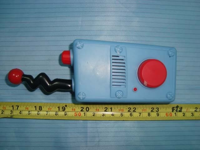
R4G20106M6001
Aug 25, 2010P&F Walkie Talkie
Equipment Class
FRF - Part 95 Family Radio Face Held Transmitter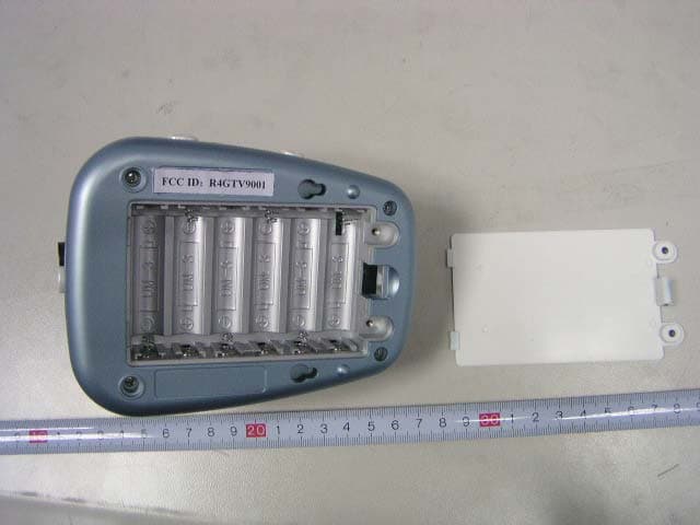
R4GTV9001
Jan 14, 2007Wireless Baby Monitor
Equipment Class
DXX - Part 15 Low Power Communication Device Transmitter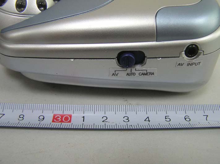
R4GJY238T01
Feb 08, 2006Wireless Baby Monitor
Equipment Class
DXX - Part 15 Low Power Communication Device Transmitter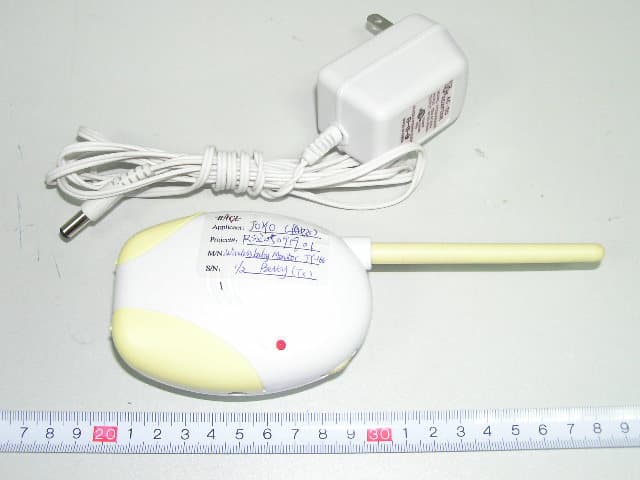
R4GJY16601
Oct 02, 2005Wireless Baby Monitor
Equipment Class
DXX - Part 15 Low Power Communication Device Transmitter
R4GJY-228
Jun 30, 20042.4 GHz Color TFT LCD AV Wireless Monitor
Equipment Class
DXX - Part 15 Low Power Communication Device Transmitter