R4GTV9001Wireless Baby Monitor
Joyo Electronics Company Limited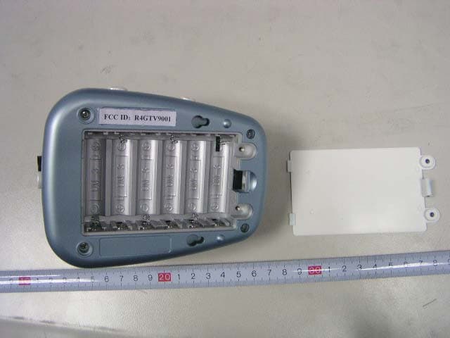
Click to zoom
Application Details
- Equipment Class
- DXX - Part 15 Low Power Communication Device Transmitter
- Date of Grant
- Jan 14, 2007
- Application Purpose
- Original Equipment
- Date of Application
- Jan 14, 2007
- Equipment Note
- Wireless Baby Monitor
- Frequency Range
- 909.00000000 - 921.00000000
- Country
- Hong Kong
Documents & Files
Document Text
Text extracted from the exhibit documents filed with the FCC. Open a document above to read the original.
Users Manual
4 fig.2 fig.1 Power Switch Battery Compartment AV Input Jack AC Adapter Jack Light Sensor Camera Lens Microphone Channel Indicator Lights Channel Selection Button Power Indicator Light Camera/AV Switch Directional Antenna Power Indicator Light Channel Indicator Lights Channel Selection Button Auto Scan Indicator Light 2.25"Color LCD Display Brightness Control Speaker fig.3 fig.4 Removable Belt Clip Battery Compartment Power/Volume Control LCD Power Switch AC Adapter Jack AV Output Jack INSTRUCTIONS You can power both the camera and receiver with an AC adapter or batteries. If you choose to operate the receiver on batteries, you can still operate the camera with the AC adapter. For long periods of non-use, we suggest removing the batteries and unplugging the AC adapters. For AC Power Insert an AC adapter into the jack marked “9V DC” on each unit and plug the adapter into an electrical outlet. When using an AC adapter, we suggest you also keep batteries in at all times as the units will automatically convert from AC to battery power during a power outage. However, if you do not keep batteries in the units, the monitor will operate on just AC power. IMPORTANT: You can only use rechargeable batteries in the receiver.You can use either rechargeable or alkaline batteries in the camera. For Battery Power The camera requires six AA alkaline or rechargeable batteries for battery operation. Rechargeable batteries can be used in the camera, however, batteries will NOT be recharged in the camera when using the AC adapter. If you are using rechargeable batteries, they will have to be removed and recharged by an external charger. The receiver requires five AA rechargeable batteries for battery operation. These batteries WILL be recharged in the receiver when using the AC adapter. DO NOT use alkaline batteries in the receiver. Remove the battery covers with a screwdriver. Insert six AA alkaline or rechargeable batteries (not included) into the camera and five AA rechargeable batteries (included) in the receiver matching positive (+) to positive (+) and negative (-) to negative (-). Replace the battery covers. Remember, if you use rechargeable batteries in the camera, you will need to recharge them with an external charger. 5 Charge the rechargeable batteries in the receiver for at least eight hours before using it on battery power for the first time. This can be done while operating the receiver on AC power or when the receiver is turned off. Charge the batteries by plugging the AC adapter directly into the receiver. The battery life is approximately six to eight hours in the camera and receiver. Replace the batteries in the camera when the Power Indicator Light turns orange. Replace the batteries in the receiver when the Power Indicator Light turns orange or the image begins to shrink. Using Your Monitor 1. Turn the camera on by sliding the Power switch to the ON position. Turn the receiver on by turning the Power/Volume control. The green Power Indicator on both units will light up when they are on. 2. Make sure the switch on the camera is set to “camera.” 3. Rotate the camera head so it faces your baby. To install the camera on the wall, use the mounting screws and anchors with the mounting template provided. 4. For daytime vision, place the camera up to ten feet from your baby making sure it is out of reach. 5. For nighttime vision, place the camera no more than six feet from your baby making sure it is out of reach.The camera has a built-in light sensor which will automatically turn on the night vision feature when there is no light detected. Remember, when using the infrared night vision, the image will only be in black and white. 6. Select the channel that gives you the best reception. Make sure both units are on the same channel. 7. If you have two cameras, you can monitor two different rooms. Set one camera to channel A and one to channel B. Change the channel on the receiver to determine which room you want to monitor. You can also set the receiver to automatically scan between the two 6 cameras. Please refer to the Automatic Channel Scan section on page 7. 8. Use the buttons on the right side of the receiver to adjust the brightness. 9. Turn the volume dial on the left side of the receiver to the desired level. SPECIAL FEATURES Receiver LCD Power Option: Battery-Saving Feature You can turn the screen of the receiver off and still maintain the sound monitor function. To use this function, slide the LCD Power switch on the receiver to the OFF position. The use of this feature will prolong the life of the batteries in the monitor when powering the monitor with batteries only. Automatic Infrared Night Vision The infrared night vision function is designed to allow the camera to pick up images even when the room is dark. Using the built-in light sensor, the camera will automatically convert to night vision when the level of light is low. Remember, when using infrared night vision, the image will be in black and white. Automatic Channel Scan Your monitor can operate with two cameras. The Automatic Channel Scan function lets you automatically scan between both channels if two cameras are being used at the same time. (If you have Model #TV900, please call us at 1-800-430-0222 to find out where you can purchase an additional camera.) To activate this feature, set one camera to channel A and the other to channel B. Turn on the Automatic Channel Scan function by pressing the Channel Selection button on the receiver until the green Auto Scan Indicator lights up. When this feature is on, the receiver will scan through the two channels automatically. It will stop at each channel and display the image and monitor the sounds from each camera for approximately five seconds. To deactivate the auto scan feature, press the Channel Selection button again. 7 Audio/Visual Output Link This feature allows you to monitor your baby on your television. Connect the receiver to your own television with the cable provided.…
Text truncated - open the document above for the full version.
Block Diagram
JY9001 BLOCK DIAGRAM ANT 909MHz 921MHz 4.5MHz OSCILLATOR(Q11 、 B1 、 D3 、 F1) AUDIO OF MIC PHONE AMP AND AGC (IC1C 、 Q9 、 Q10) VCO (D4 、 D11,Q4) MCU (IC2) RF AMP (Q5 、 Q6) PLL SYNTHESIZER (IC3 、 Q12) EXTERNAL AUDIO SIGNAL DETECTION (JACK2 、 Q24 、 、 S2) DATA RECORD IC4 (93C46) EXTERNAL VIDEO SIGNAL DETECTION (JACK2 ,Q24 、 、 S2) VIDEO AND INFRARED LED OF CAMERA1 Infrared night-LED CONTROL CIRCUIT (Q22 、 Q23 、 IC1D) BATTERY RECHARGING :IC5, Q3, Q15, Q16, D6 POWER SUPPLY ( BAT1 OR EXTERNAL ADAPTER 、 S1) CHANNEL SELECTION AND INDICATION (SW1 、 LED1 、 LED2 、 ) LOW POWER INDICATION (IC1A 、 IC1B 、 Q17 、 LED5) 5V REGULATOR (IC6)
Cover Letter(s)
JOYO Electronics Company Limited Non-Confidential Authorization Date: January 9, 2007 FEDERAL COMMUNICATIONS COMMISSIONS Authorization and Evaluation Division 7435 Oakland Mills Road Columbia, MD 21046 Subject: Non-Confidentiality Request regarding application for certification of FCC ID: (R4GTV9001) . To: whom it may concern, We JOYO Electronics Company Limited confirm that all the information accompanying this application as outlined below are permitted to release to the public. Product Name: Wireless Baby Monitor FCC ID: R4GTV9001 Sincerely Yours, Signature: Typed or Printed Name: Dominic Wong Title: Sales Manager Company Name: JOYO Electronics Company Limited Form 05
Cover Letter(s)
JOYO Electronics Company Limited FCC Authorization Date: January 9, 2007 FEDERAL COMMUNICATIONS COMMISSIONS Authorization and Evaluation Division 7435 Oakland Mills Road Columbia, MD 21046 Subject: Agent Authorization To whom it may concern: We JOYO Electronics Company Limited , the undersigned, Hereby authorizes Bay Area Compliance Laboratory Corporation to act on its behalf in all matters relating to application for Equipment authorization, including the signing of all documents relating to these matters. All acts carried out by Bay Area Compliance Laboratory Corporation on our behalf shall have the same effect as our own action. We, the undersigned, hereby certify that we are not subject to a denial of federal benefits, that includes FCC benefits, pursuant to Section 5301 of the Anti-Drug Abuse Act of 1988, 21 U.S.C. 853(a). This authorization is valid until further written notice from the applicant. Sincerely Yours, Signature: Typed or Printed Name: Dominic Wong Title: Sales Manager Company Name: JOYO Electronics Company Limited
External Photos
External Photos EUT - Full View EUT - Top View EUT - Bottom View EUT – Battery Cover Open View
ID Label/Location Info
ID Label/Location Label Location Information Specifications: Text is Black or white in color and is left justified. Labels are printed in indelible ink on permanent adhesive backing or silk-screened onto the EUT or shall be affixed at a conspicuous location on the EUT. Refer to the below arrow.
ID Label/Location Info
ID Label Label FCC ID: R4GTV9001
Internal Photos
Internal Photos EUT – EUT Inside View Antenna Port EUT – Camera Uncovered View EUT - PCB 1 Top View EUT - PCB 1 Bottom View EUT - PCB 1 Unshielded Bottom View EUT - PCB 2 Top View EUT - PCB 2 Bottom View
Operational Description
JY9001 circuit of description 1、When battery (or adapter) is inserted properly; Turn on power switch (S1) in ON position, Led5 of the power indicator lights up green. (if low power, Led5 of the power indicator lights up orange) 2、Channel setting: By pressing button (sw1), 2 channel of A/B/can be selected, and one led of LED1、LED2、lights up green, It indicates this channel being set. 3、Signal source selection: 1) 、 when switch (SW2) is in “CAMERA” position, VIDEO signal only from camera1, AUDIO signal only from mic phone. 2) 、 when switch (SW2) is in “AV” position, external VIDEO& AUDIO signal only external. 4、AUDIO signal modulation: 1) AUDIO signal from microphone amplified by IC1C or external AUDIO from jack2 can be sending into sub-carrier oscillator of 4.5MHZ, 2) the sub-carrier of 4.5 MHz send into VCO and modulated. 5、VIDEO signal modulation: 1)VIDEO signal from camera1 or external jack2 sent into VCO and modulated 6、VCO oscillator circuit: Frequency of VCO selection by pressing SW1, MCU send data of channel into PLL synthesizer (IC3), at the same time this data will be save by IC5 (93C46) and then PLL synthesizer (IC3) send signal to VCO, VCO can generate 2 kinds of RF signal (909MHz/921MHz). 7、RF AMP circuit: RF signal of VCO is amplified by Q5 and Q6, and then transmission out by ANT. 8、Power supply and low power indicate: 1) IC6 regulate 5V voltage, when battery voltage is low, LED5 lights up orange. 9、Infrared night-led control;In darkness, value of R76 (CDS) enlarges; Voltage of pin 1 of CAMERA1 became low, and the LED of infrared in CAMERA1 light up. In daylight value of R85 (CDS) reduce, Voltage of pin 1 of CAMERA1 became high, the LED of infrared in CAMERA1 light out.
Schematics
1 2 3 4 5 6 7 8 ABCD 8 7 6 5 4 3 2 1 D CBA Title Number Revision Size A3 Date: 19-Dec-2006 Sheet of File: G:\ ড়᭛ӊ \ 䞥㕮 \JY900\2006-12-14\JY900T-V3\JY900T-V3.DDB Drawn By: C27 475P R17 472 R18 472 R48 104 R19 105 R51 683 MIC1 C35 103P C36 104P C37 104P C45 224P C46 82P R55 NC R77 104 R49 304 R41 NC R79 332 D2 4148 D1 4148 C48 475P Q10 3904 Q9 3904 R87 473 R40 NC R42 NC R50 103 R43 101 R44 514 D32105C49 82P C50 30P C9101P Q8 3904 123 46 B1 2605 R88 102 R91 472 C41 102P C42 10P F1 6MHz R100 102 R89 122 R116 681 R117 101 R126 472 C40 102P 18 916 IC3 SP5655 L115uH C38 104P C61 103P JY900T 3.0 1 1 LH.LAN VRF C10 104P R65 104 R104 473 R101 273 R143 154 R66 104 R56 NC Q23906 R57 NC R58 NC C51 101P C52 NC C13 104P LV CHC PWC C53 102P C59 102P C63 105P C68 103P C62 18P C29 475P XT1 4MHz Q12 3904 R32 103 R105 473 R119 102 R33 103 R102 103 C69 NC RFIN VPLL 5V 10 9 8 IC1C LM324 C47 225P R92 152 R93 223 C70 NC CLK DATA 14 58 IC4 93C46 CSCLK DATA DO 5V C60 102P LED1LED3 LED2LED4 R130 471 R128 471 R129 471 R131 471 VPLL R82 472 CS DO C28 475P R31 393 Q7 3906 R29 821 R38 221 R28 392 R39 152 VMOD VPLL R106 473 SW1CH PIN14 C12 104P AMOD R80 472 TP3 TP2 R34 103 TP1 R52 151 R54 471 R145 102 C24 105P R62 472 R46 223 R53 151 Q11 3904 R26 104 R45 152 C23 104P C6NC C7NC R90 NC C8NC P52 1 P53TCCRSTVSSP60P61P62P63 9 P64 10 P65P66P67 VDD OSCO OSCI P50P51 18 IC2EM78P156 R171 472 Q37 3904 R172 104 R173 473 R180 102 R181 102 ANT1 C43 6P C44 6P C54 1P C34 101P C55 3P Q6PRF957 Q5 PRF957 Q4 PRF957 R14 183 R15 47 R13 101 R12 104 R11 101 R10 822 R20 331 R16 682 C74 2P C73 2P C32 3P C20 3P C21 102P C33 102P C26 102P C17 102P C64 4P C16 30P C11 NC C5 102P C4105P C58 1P C56 NC C71 4P C72 2P D4 1SV245 R8101 L2 15uH RFIN VRF 1234 JACK2 JACK-AV AUDIO VIDEO IC6 5002 C91 100uF/16V C92 100uF C39 104P 5V C15 104P C14 104P VDD TP4 Q3 3906 R5223 R6223 R118 331 R158 331 R176 102 R177 102 R175 NC R179 221 TP5 TP6 TP7 32 1 411 IC1ALM324 56 7 IC1BLM324 R76 154 R170 822 R37 103 R112 513 R113 473 R165 104 R97 471 R96 102 C19 105P C22 104P Q17 3904 G R LED5 GR VPLL VPLL VDD VPLL C18 104P LV R21 68 R24 102 R25 0R VIDEO CAMERA VMOD C2104PC3104P R22 683 R23 102 R27 101 PIN14 AUDIO AMOD 1 1 2 2 3 3 4 4 5 5 6 6 S2 SW-DPDT R61 NC R63 472 VCH C67 104P C66 475P D9 4148 D10 4148 VCH Q13906 Q15 B1182 Q16 3904 R35 222 R36.8R26.8 R10 R60 10 R47 10 R36 NC D5 FM5817 D6 FM5817 D8FM5817D7 FM5817 BAT1 BAT S1 ON/OFF R4103 JACK1 JACK3 IC578L05 C65 105P C1475P VCH CHC Q20 2SA1797 Q18 3904 Q13 3904 R67 473 R30 222 R70 102 R71 102 R72 NC Q21 2SA1797 Q14 3904 R7223 C30 475P C31 475P R59 222 R74 103 VPLL 5V VRF VDD VDD 5V PWC 1 1 234 CAMERA1 CON-4 CAMERA C25 104P R84 225 Q23 3904 R83 332 R73 NC 1213 14 IC1DLM324 VPLL R75 514 R78 683 R86 224 Q22 2SA1797 R9223 Q19 3904 R68 472 VDD R64 223 R85 CDS R69 472 C75 102P TP8 C76 475P Q24 3904 R94 472 R98 473 R95 104 C77 475P VPLL C78 475P C79 475P XT2 4MHz R99 681 R81 101 C80 22P C57 22P L322uH D11 1SV245 R103 105 R107 472 TP9 1 2 3 4 ABCD 4 3 2 1 D CBA Title Number Revision Size A4 Date: 19-Dec-2006 Sheet of File: G:\P99(NEW)\CAMERA\515_G4_14X11 2005.DDB Drawn By: SGND 1 SVDD 2 VcBRT 3 BPAVE 4 Rsvd5 5 AGND 6 AVDD 7 RGSW 8 CEXP 9 HSAT 10 Rsvd11 11 SMTawb 12 EVDD 13 EGND 14 BUCO 15 GYYO 16 RVCVO 17 OVDD 18 G2X 19 HIGAIN 20 BKLT 21 XCLK1 22 XCLK2 23 PAL 24 DVDD 25 DGND 26 GAMMA 27 AGCEN 28 AVVBEN 29 AVVBTM 30 VADPXO 31 VHSYNC/MIR 32 FSO 33 FODD/I2C 34 PALSW 35 FSln 36 PWDN 37 MODE0 38 MODE1 39 HSHP 40 DEVDD 41 DEGND 42 SCL 43 SDA 44 VREF1 45 VREF2 46 VREF3 47 VREF4 48 IC1 LED2 LED LED7 LED LED8 LED LED9 LED LED10 LED LED1 LED LED3 LED LED4 LED LED5 LED LED6 LED C8 104P C9104P C10 104P C11 104P C12 104P R18 NC C13 104P R810K R7100K R61M Y1 NTSC Y1=14.31818MHz C433P C3 33P R1 10K/NC C5 104P 5V R510K R4NC R17 10K R11 101 R933 R12 10K R10 10K R21 10K R20 10K Q2 3904 Q33904 Q73904 R19 3K9 5V VIDEO MODE1 5V C7 47UF C6 104P 5V MODE1 Q13904 Q53904 Q63906 R22K2 R310K R15 10 R16 10K PIR 5V Q4 NC R13 0 R14 NC 5V IN G OUT U1 78L05 C1104P C2104P 5V 1234 CON1 CON4 9V 9V VIDEOPIR 5V C7A 47UF R22 NC CAMERA(C)-V2 PAL Y1=17.734475MHz
Test Report
Note: This test report is for the customer shown above and their specific product only. It may not be duplicated or used in part without prior written consent from Bay Area Compliance Laboratory Corp. (Shenzhen). This report must not be used by the customer to claim product certification, approval, or endorsement by NVLAP, NIST or any agency of the Federal Government. FCC PART 15.249 EMI MEASUREMENT AND TEST REPORT For JOYO Electronics Company Limited Unit D, 13/F., World Tech Centre, 95 How Ming Street, Kwun Tong, Kowloon, Hong Kong FCC ID: R4GTV9001 This Report Concerns: Original Report Equipment Type: Wireless Baby Monitor Test Engineer: Deny Xiong Report No.: RSZ06122801 Test Date: 2007-01-03 to 2007-01-05 Report Date: 2007-01-08 Reviewed By: EMC Manager: Boni Baniqued Prepared By: Bay Area Compliance Laboratory Corp. (Shenzhen) 6/F, the 3rd Phase of WanLi Industrial Building, ShiHua Road, FuTian Free Trade Zone Shenzhen, Guangdong, China Tel: +86-755-33320018 Fax: +86-755-33320008 JOYO Electronics Company Limited FCC ID: R4GTV9001 Report # RSZ06122801 Page 2 of 27 FCC PART 15.249 Report TABLE OF CONTENTS GENERAL INFORMATION.......................................................................................................................................3 PRODUCT DESCRIPTION FOR EQUIPMENT UNDER TEST (EUT) .....................................................................................3 OBJECTIVE...................................................................................................................................................................3 RELATED SUBMITTAL(S)/GRANT(S).............................................................................................................................3 TEST METHODOLOGY..................................................................................................................................................3 TEST FACILITY.............................................................................................................................................................3 LOCAL SUPPORT EQUIPMENT LIST AND DETAILS........................................................................................................4 SYSTEM TEST CONFIGURATION ..........................................................................................................................5 JUSTIFICATION.............................................................................................................................................................5 EQUIPMENT MODIFICATIONS.......................................................................................................................................5 CONFIGURATION OF TEST SETUP.................................................................................................................................6 BLOCK DIAGRAM OF TEST SETUP................................................................................................................................6 SUMMARY OF TEST RESULTS ...............................................................................................................................7 §15.203 - ANTENNA REQUIREMENT......................................................................................................................8 STANDARD APPLICABLE..............................................................................................................................................8 ANTENNA CONNECTOR CONSTRUCTION......................................................................................................................8 §15.207 - CONDUCTED EMISSION ..........................................................................................................................9 MEASUREMENT UNCERTAINTY....................................................................................................................................9 EUT SETUP..................................................................................................................................................................9 EMI TEST RECEIVER SETUP.......................................................................................................................................10 TEST EQUIPMENT LIST AND DETAILS.........................................................................................................................10 TEST PROCEDURE......................................................................................................................................................10 TEST RESULTS SUMMARY..........................................................................................................................................10 TEST DATA................................................................................................................................................................11 PLOT(S) OF TEST DATA..............................................................................................................................................12 §15.205 §15.209(A) §15.249(A) - RADIATED EMISSION ......................................................................................17 MEASUREMENT UNCERTAINTY..................................................................................................................................17 EUT SETUP................................................................................................................................................................17 EMI TEST RECEIVER SETUP.......................................................................................................................................18 TEST EQUIPMENT LIST AND DETAILS.........................................................................................................................18 TEST PROCEDURE..............................................................................................…
Text truncated - open the document above for the full version.
Test Setup Photos
Test Setup Photos Conduction Emission - Front View Conduction Emission - Rear View 30 MHz – 1000 MHz: Radiated Emission - Front View 30 MHz – 1000 MHz: Radiated Emission - Rear View Above 1 GHz: Radiated Emission - Front View Above 1 GHz: Radiated Emission - Rear View
Contact Information
Applicant
George Lau(Admin)
Technical Contact
Bay Area Compliance Lab Corp(Shenzhen)Boni Baniqued
[email protected]86-755-33320018
6/F, 3rd Phase of Wanli Industrial Building · Shenzhen · China
Test Firm
Bay Area Compliance Laboratory Corp. (Shenzhen)John Chan
Technical Specifications
| # | Rule Parts | Frequency Range | Power Output |
|---|---|---|---|
| 1 | 15C | 909 MHz - 921 MHz | - |
Other Applications from Joyo Electronics Company Limited
R4G20106M6001
Aug 25, 2010P&F Walkie Talkie
Equipment Class
FRF - Part 95 Family Radio Face Held Transmitter
R4GJY238T01
Feb 08, 2006Wireless Baby Monitor
Equipment Class
DXX - Part 15 Low Power Communication Device Transmitter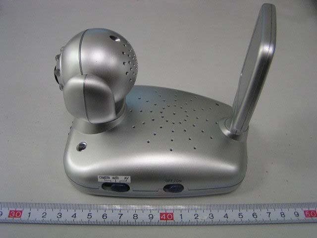
R4GJY278T01
Jan 18, 2006Wireless Baby Monitor
Equipment Class
DXX - Part 15 Low Power Communication Device Transmitter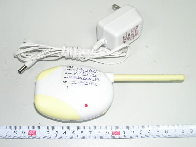
R4GJY16601
Oct 02, 2005Wireless Baby Monitor
Equipment Class
DXX - Part 15 Low Power Communication Device Transmitter
R4GJY-228
Jun 30, 20042.4 GHz Color TFT LCD AV Wireless Monitor
Equipment Class
DXX - Part 15 Low Power Communication Device Transmitter