R4N-AW2400MR2.4 GHz Wireless Ethernet Module
Avalan Wireless Systems Incorporated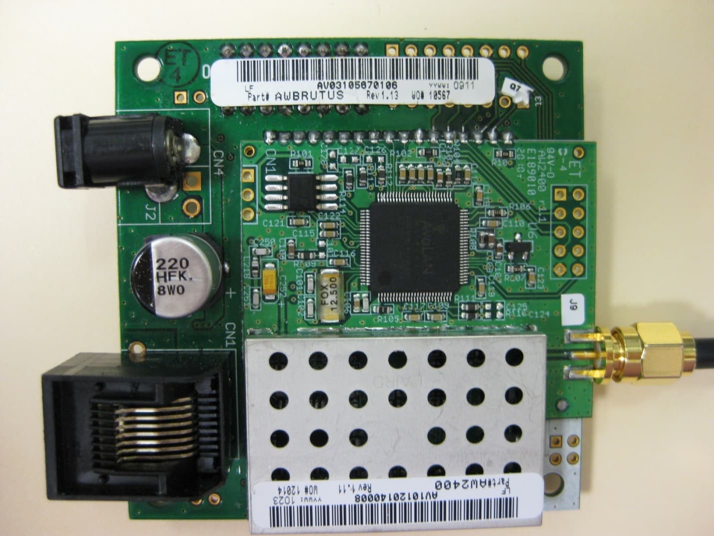
Click to zoom
Application Details
- Equipment Class
- DTS - Digital Transmission System
- Date of Grant
- Nov 08, 2010
- Application Purpose
- Original Equipment
- Date of Application
- Nov 08, 2010
- Equipment Note
- 2.4 GHz Wireless Ethernet Module
- Frequency Range
- 2416.66700000 - 2475.00000000
- Country
- United States
Documents & Files
Document Text
Text extracted from the exhibit documents filed with the FCC. Open a document above to read the original.
Users Manual
USER’S MANUAL Industrial-grade, long-range wireless Ethernet systems AvaLAN WIRELESS 2.4 GHz Wireless Ethernet Module Evaluation Kit AW2400mTR-EVAL AW2400mTRUser’s Manual PAGE 2 Technical support (650) 384-0000www.avalanwireless.com © 2010 by AvaLAN Wireless Systems Inc. All rights reserved. Revision 09.30.2010 125A Castle Drive Madison, AL 35758 Sales: (866) 533-6216 Technical Support: (650) 384-0000 Customer Service: (650) 641-3011 Fax: (650) 249-3591 Thank you for your purchase of the AW2400mTR-EVAL Wireless Ethernet Module Evaluation Kit. If you have any questions when configuring your AvaLAN system, the best place to get answers is to visit www.avalanwireless.com. You will also find the latest updates there. If more assistance is needed, send email to [email protected]. To speak to a live technician, please call technical support at the number below during normal business hours. This product is warranted to the original purchaser for normal use for a period of 360 days from the date of purchase. If a defect covered under this warranty occurs, AvaLAN will repair or replace the defective part, at its option, at no cost. This warranty does not cover defects resulting from misuse or modification of the product. Limited Warranty PAGE 3 Technical support (650) 384-0000www.avalanwireless.com User’s ManualAW2400mTR Operational summary The AW2400mTR Radio Module allows the user to create a long-range, wireless Ethernet network with up to 16 subscriber units per access point. The configu- ration may include any combination of AW2400mTR, AW2400xTR, AW2400iTR and AW2400xTP radios. Configuring a wireless link with the AW2400mTR requires the establishment of six elements: • Each radio must know whether it is to be an access point (AP) or subscriber unit (SU). • Each radio must have an IP address that is unique among all others on the same network. • The AP must know how many SUs are expecting communication with it. • The AP and any given SU must agree on which radio frequency channel they are using. This can be manually set or allowed to change automatically. • The SU must be assigned a unique subscriber ID to specify which time division slot it will use when communicating with the AP. • The AP and any given SU must share a common 128-bit encryption key. AW2400mTR radios may be configured by two different methods. They may be con- nected to a computer that will run a web browser, setting parameters via their built-in browser interfaces. They may also be programmed via the “easy key” meth- od using the DIP switches and LEDs on the module. The access point (AP) automatically scans for the best of the 29 available radio fre- quency channels, encrypts Ethernet data received from the network, and transmits it wirelessly to the correct subscriber unit (SU). The AP is constantly monitoring the radio link and can automatically change the channel if performance is degraded due to interference. If two AP units are very close to one another, they may interfere if operating on adjacent frequency channels. Place them at least 10 feet apart or manually select non-adjacent channels for their operation. Also, the SU should be placed at least 10 feet from the AP to avoid overloading the radio’s receiver. Any 10/100 BaseT Ethernet client device (ECD) can be connected to an AW2400mTR subscriber unit. Each SU encrypts Ethernet traffic received from the attached ECD and transmits the data wirelessly to its AP. Each SU can be plugged directly into an ECD without adding drivers or loading software. Essentially, once the AP/SU pair is configured and running it behaves like a continuous Ethernet cable. AW2400mTRUser’s Manual PAGE 4 Technical support (650) 384-0000www.avalanwireless.com Evaluation Kit Contents The AW2400mSPI-EVAL 2.4 GHz Wireless Ethernet Module Evaluation Kit contains two each of the following items: • AW2400mSPI Wireless Ethernet Modules • AW2-2400 Omnidirectional Antennas • AW-P8 Antenna to Radio Connectors • AW-POE Power Over Ethernet Injectors • AW-12VPS 12 Volt Power Supplies Additional quantities of any of these components may be purchased from AvaLAN Wireless or our distributors. To power up a radio module, connect the antenna via the pigtail cable provided. Connect an Ethernet cable to the RJ-45 jack on the module. Power may be sup- plied to the module using the 12 VDC wall hanger power supply either through the Ethernet cable using the POE or directly into the P5 jack on the module. Provide some physical separation between two radio modules — at least five feet. If their antennas are in close proximity, the module radio receivers will be over- loaded, causing degredation in the bit error rate and slower link performance. PAGE 5 Technical support (650) 384-0000www.avalanwireless.com User’s ManualAW2400mTR Physical Dimensions 23 mm 70 mm 66 mm Power: 5-48 VDC Ethernet: 10/100T Power: 9-48 VDC Antenna: Reverse polarity SMA Mounting Holes Mounting Holes 2.4 GHz Channels ChannelCenter FrequencyChannelCenter Frequency 0Auto Mode152.445833 GHz 12.416667 GHz162.447917 GHz 22.418750 GHz172.450000 GHz 32.420833 GHz182.452083 GHz 42.422917 GHz192.454167 GHz 52.425000 GHz202.456250 GHz 62.427083 GHz212.458333 GHz 72.429167 GHz222.460417 GHz 82.431250 GHz232.462500 GHz 92.433333 GHz242.464583 GHz 102.435417 GHz252.466667 GHz 112.437500 GHz262.468750 GHz 122.439583 GHz272.470833 GHz 132.441667 GHz282.472917 GHz 142.443750 GHz292.475000 GHz AW2400mTRUser’s Manual PAGE 6 Technical support (650) 384-0000www.avalanwireless.com Browser Interface Configuration 1. Digital configuration is done by means of the AW2400mTR’s built in browser interface. It should be powered on and connected at least temporarily to a network containing a computer that can run a conventional web browser. 2. Download the AvaLAN IP Discovery Utility from our website and extract ipfinder.exe from the zip archive, placing it on your desktop or in a convenient folder. http://www.avalanwireless.com/ipfinder/ipfinder.zip Note that this u…
Text truncated - open the document above for the full version.
Cover Letter(s)
Request for Confidentiality Date: September 30, 2010 Subject: Confidentiality Request for FCC ID: R4N-AW200MR Pursuant to FCC 47 CRF 0.457(d) and 0.459 and IC RSP-100, Section 10, the applicant requests that a part of the subject FCC application be held confidential. Type of Confidentiality Requested Exhibit Short Term Permanent Block Diagrams Short Term External Photos Short Term Permanent Internal Photos Short Term Permanent Operation Description/Theory of Operation Short Term Permanent Parts List & Placement/BOM Short Term Permanent Tune-Up Procedure Short Term Permanent Schematics Short Term Test Setup Photos Short Term Permanent User’s Manual AvaLAN Wireless Systems has spent substantial effort in developing this product and it is one of the first of its kind in industry. Having the subject information easily available to "competition" would negate the advantage they have achieved by developing this product. Not protecting the details of the design will result in financial hardship. Permanent Confidentiality: The applicant requests the exhibits listed above as permanently confidential be permanently withheld from public review due to materials that contain trade secrets and proprietary information not customarily released to the public. Sincerely, Michael R Derby CTO/Founder
Cover Letter(s)
125A Castle Drive, Madison, AL 35758 –T (650) 384 0000 – F (650) 249 3591 March 30, 2010 To Whom It May Concern: AvaLAN Wireless would like to apply for Modular FCC approval. This letter is our application for such according to FCC public notice DA 00-1407. AW2400MR Modular Transmitter Requirements Modular Transmitter Requirements Manufacturer Clarification A – In order to be considered a transmitter module, the device must be a complete RF transmitter, i.e., it must have its own reference oscillator (e.g., VCO), antenna, etc. The only connectors to the module, if any, may be the power supply and modulation/data inputs. The transmitter is complete with its own reference oscillator, antenna. The only connectors provided are the DC supply, Data, and RF ports. B – Compliance with FCC RF Exposure requirements may, in some instances, limit the output power of a module and/or the final applications in which the approved module may be employed. The radio complies with MPE per 2.1091 for use with mobile or fixed base stations. C – While the applicant for a device into which an authorized module is installed is not required to obtain a new authorization for the module, this does not preclude the possibility that some other form of authorization or testing may be required for the device (e.g., a WLAN into which an authorized module is installed must still be authorized as a PC peripheral, subject to the appropriate equipment authorization). The equipment complies with FCC Part 15, Subpart B, Class B – Unintentional radiators. D – In the case of a modular transceiver, the modular approval policy only applies to the transmitter portion of such devices. Pursuant to Section 15.101(b), the receiver portion will either be subject to Verification, or it will not be subject to any authorization requirements (unless it is a Scanning Receiver, in which case it is also subject to Certification, pursuant to Section 15.101(a)). The receiver operates in 2.4GHz ISM band and complies with FCC Part 15, Subpart B Radio Receivers. 125A Castle Drive, Madison, AL 35758 –T (650) 384 0000 – F (650) 249 3591 Modular Transmitter Requirements Manufacturer Clarification E – The holder of the grant of equipment authorization (Grantee) of the module is responsible for the compliance of the module in its final configuration, provided that the OEM, integrator, and/or end user has complied with all of the instructions provided by the Grantee which indicate installation and/or operating conditions necessary for compliance. End users must conform with the following instructions stated in the users’ manual: - Labeling requirement for equipment using this modular transmitter. - RF Exposure information for compliance with FCC Rules 2.1091 or 2.1093 are specified in the user manual for OEM, integrator, and/or end user. 1. The modular transmitter must have its own RF shielding. This is intended to ensure that the module does not have to rely upon the shielding provided by the device into which it is installed in order for all modular transmitter emissions to comply with Part 15 limits... Such coupling may result in non-compliant operation. The modular transmitter has its own RF shielding. 2. The modular transmitter must have buffered modulation/data inputs (if such inputs are provided) to ensure that the module will comply with Part 15 requirements under conditions of excessive data rates or over-modulation. The modular transmitter has buffered modulation/data inputs. 3. The modular transmitter must have its own power supply regulation. This is intended to ensure that the module will comply with Part 15 requirements regardless of the design of the power supplying circuitry in the device into which the module is installed. The modular transmitter has its own power supply regulation. 4. The modular transmitter must comply with the antenna requirements of Section 15.203 and 15.204c. The antenna must either be permanently attached or employ a “unique” antenna coupler (at all connections between the module and the antenna, including the cable). Any antenna used with the module must be approved with the module; either at the time of initial authorization or through a Class II permissive change. The “professional installation” provision of Section 15.203 may not be applied to modules. The radio complies with Rules 15.203 and 15.204c. The radio may have either a permanently attached wire antenna or a unique antenna coupler (RPSMA or RPTNC) for all other approved antennas. 125A Castle Drive, Madison, AL 35758 –T (650) 384 0000 – F (650) 249 3591 Modular Transmitter Requirements Manufacturer Clarification 5. The modular transmitter must be tested in a stand-alone configuration, i.e., the module must not be inside another device during testing. This is intended to demonstrate that the module is capable of complying with Part 15 emission limits regardless of the device into which it is eventually installed... The modular transmitter was tested in a stand-alone configuration. 6. The modular transmitter must be labeled with its own FCC ID number, and, if the FCC ID is not visible when the module is installed inside another device, then the outside of the device into which the module is installed must also display a label referring to the enclosed module... The modular transmitter is labeled with its own FCC ID number. The label is fixed on the shield. 7. The modular transmitter must comply with any specific rule or operating requirements applicable to the transmitter and the manufacturer must provide adequate instructions along with the module to explain any such requirements. The user manual for the AW2400MR contains adequate instructions relating to the usage, approved antennas, and power supply requirements of the modular transmitter. 8. The modular transmitter must comply with any applicable RF exposure requirements. The modular transmitter was tested to applicable RF exposure requirements. Sincerely, Michael R Derby CEO AvaLAN Wireless
External Photos
EXTERNAL PHOTOS Company Name AvaLAN Wireless Systems Model # AW2400MR FCC ID # R4N‐AW2400MR IC # 5303A‐AW2400MR Page 1 of 6 Module with Antenna Connected EXTERNAL PHOTOS Company Name AvaLAN Wireless Systems Model # AW2400MR FCC ID # R4N‐AW2400MR IC # 5303A‐AW2400MR Page 2 of 6 Close Up Front Side EXTERNAL PHOTOS Company Name AvaLAN Wireless Systems Model # AW2400MR FCC ID # R4N‐AW2400MR IC # 5303A‐AW2400MR Page 3 of 6 Close Up Back Side EXTERNAL PHOTOS Company Name AvaLAN Wireless Systems Model # AW2400MR FCC ID # R4N‐AW2400MR IC # 5303A‐AW2400MR Page 4 of 6 Close Up of Antenna Connection EXTERNAL PHOTOS Company Name AvaLAN Wireless Systems Model # AW2400MR FCC ID # R4N‐AW2400MR IC # 5303A‐AW2400MR Page 5 of 6 Close Up of Antenna Connection EXTERNAL PHOTOS Company Name AvaLAN Wireless Systems Model # AW2400MR FCC ID # R4N‐AW2400MR IC # 5303A‐AW2400MR Page 6 of 6 Close Up of ID Label
ID Label/Location Info
LABELPHOTO Company Name AvaLAN Wireless Systems Model # AW2400MR FCC ID # R4N‐AW2400MR IC # 5303A‐AW2400MR Page 1 of 1 ID Label
Internal Photos
INTERNAL PHOTOS Company Name AvaLAN Wireless Systems Model # AW2400MR FCC ID # R4N‐AW2400MR IC # 5303A‐AW2400MR Page 1 of 5 Shield Removed INTERNAL PHOTOS Company Name AvaLAN Wireless Systems Model # AW2400MR FCC ID # R4N‐AW2400MR IC # 5303A‐AW2400MR Page 2 of 5 INTERNAL PHOTOS Company Name AvaLAN Wireless Systems Model # AW2400MR FCC ID # R4N‐AW2400MR IC # 5303A‐AW2400MR Page 3 of 5 INTERNAL PHOTOS Company Name AvaLAN Wireless Systems Model # AW2400MR FCC ID # R4N‐AW2400MR IC # 5303A‐AW2400MR Page 4 of 5 Internal Close Up‐Shield Removed INTERNAL PHOTOS Company Name AvaLAN Wireless Systems Model # AW2400MR FCC ID # R4N‐AW2400MR IC # 5303A‐AW2400MR Page 5 of 5
RF Exposure Info
Prepared For: AvaLAN Wireless EUT: Wireless Ethernet Bridge LS Research, LLC Report # 310038 Model #: AW2400MR Template: 15.109 Class B DTS RX 10-22-09 LSR Job #: C-881 Serial #: AV10120140008 Page 60 of 65 EXHIBIT 14 MPE CALCULATIONS The following MPE calculations are based on a 5 dBi Omni-directional monopole antenna, with a measured ERP of 120.77 dBμV/m, at 3 meters, and conducted RF power of +18.2 dBm as presented to the antenna. The maximum gain of this antenna, based on the manufacturer’s documentation is 5 dBi.
Test Report
W66 N220 Commerce Court ● Cedarburg, WI 53012 ● USA Phone: 262.375.4400 ● Fax: 262.375.4248 www.lsr.com TEST REPORT #: 310038 LSR Job #: C-881 Compliance Testing of: AvaLAN AW2400MR Ethernet Bridge Serial Number: AV10120140008 Test Date(s): July 31 st – September 19 th , 2010 Prepared For: AvaLAN Wireless Attn: Mike Derby 125A Castle Drive Madison, AL 35758 In accordance with: Federal Communications Commission (FCC) Part 15, Subpart C, Section 15.247 Industry Canada (IC) RSS 210 Annex 8 Digital Modulation Transmitters (DTS) Operating in the Frequency Band 2400 MHz – 2483.5 MHz This Test Report is issued under the Authority of: Thomas T. Smith, Manager EMC Test Services Signature: Date: 10.04.10 Quality Assurance: Ryan Urness, EMC Laboratory Manager Signature: Date: 10.04.10 Project Engineer: Khairul Zainal, Sr. EMC Engineer Signature: Date: 10.04.10 This Test Report may not be reproduced, except in full, without written approval of LS Research, LLC. Prepared For: AvaLAN Wireless EUT: Wireless Ethernet Bridge LS Research, LLC Report # 310038 Model #: AW2400MR Template: 15.109 Class B DTS RX 10-22-09 LSR Job #: C-881 Serial #: AV10120140008 Page 2 of 65 TABLE OF CONTENTS (page 1 of 2) EXHIBIT 1: INTRODUCTION 5-6 1.1 Scope 5 1.2 Normative References 5 1.3 LS Research, LLC Test Facility 6 1.4 Location of Testing 6 1.5 Test Equipment Utilized 6 EXHIBIT 2: PERFORMANCE ASSESSMENT 7-9 2.1 Client Information 7 2.2 Equipment Under Test (EUT) Information 7 2.3 Associated Antenna Description 7 2.4 EUT’s Technical Specifications 8 2.5 Product Description 9 EXHIBIT 3: EUT OPERATING CONDITIONS & CONFIGURATIONS DURING TESTS 10 3.1 Climate Test Conditions 10 3.2 Applicability & Summary of EMC Emission Test Results 10 3.3 Modifications Incorporated in the EUT for Compliance Purposes 10 3.4 Deviations & Exclusions from Test Specifications 10 EXHIBIT 4: DECLARATION OF CONFORMITY 11 EXHIBIT 5: RADIATED EMISSIONS TESTING – TRANSMITTER 12-27 5.1 Test Setup 12 5.2 Test Procedure 12 5.3 Test Equipment Utilized 13 5.4 Test Results 13 5.5 Calculation of Radiated Emissions Limits 14 5.6 Radiated Emissions Test Data Chart 15 5.7 Test Setup Photo(s) – Radiated Emissions Test 17 5.8 Screen Captures – Radiated Emissions Test 23 EXHIBIT 6: RADIATED EMISSIONS TESTING – RECEIVER 28-35 6.1 Test Setup 28 6.2 Test Procedure 28 6.3 Test Equipment Utilized 29 6.4 Test Results 29 6.5 Calculation of Radiated Emissions Limits 30 6.6 Radiated Emissions Test Data Chart 31 6.7 Test Setup Photo(s) – Radiated Emissions Test 32 6.8 Screen Captures – Radiated Emissions Test 33 Prepared For: AvaLAN Wireless EUT: Wireless Ethernet Bridge LS Research, LLC Report # 310038 Model #: AW2400MR Template: 15.109 Class B DTS RX 10-22-09 LSR Job #: C-881 Serial #: AV10120140008 Page 3 of 65 TABLE OF CONTENTS (Page 2 of 2) EXHIBIT 7: CONDUCTED EMISSIONS TEST, AC POWER LINE 36-43 7.1 Test Setup 36 7.2 Test Procedure 36 7.3 Test Equipment Utilized 36 7.4 Test Results 37 7.5 FCC Limits of Conducted Emissions at the AC Mains Ports 37 7.6 Conducted Emissions Test Data Chart 38 7.7 Test Setup Photo(s) – Conducted Emissions Test 39 7.8 Screen Captures – Conducted Emissions Test 40 EXHIBIT 8: OCCUPIED BANDWIDTH 44-46 8.1 Limits 44 8.2 Method of Measurements 44 8.3 Test Equipment List 44 8.4 Test Data 44 8.5 Screen Captures – Occupied Bandwidth 45 EXHIBIT 9: BAND-EDGE MEASUREMENTS 47-48 9.1 Method of Measurements 47 EXHIBIT 10: POWER OUTPUT (CONDUCTED): 15.247(b) 49-51 10.1 Method of Measurements 49 10.2 Test Equipment List 49 10.3 Test Data 49 10.4 Screen Captures – Power Output (Conducted) 50 EXHIBIT 11: POWER SPECTRAL DENSITY: 15.247(e) 52-54 11.1 Limits 52 11.2 Test Equipment List 52 11.3 Test Data 52 11.4 Screen Captures – Power Spectral Density 53 EXHIBIT 12: SPURIOUS RADIATED EMISSIONS: 15.247(d) 55-58 12.1 Limits 55 12.2 Test Equipment List 55 12.3 Test Data 56 12.4 Screen Captures – Spurious Radiated Emissions 56 EXHIBIT 13: FREQUENCY & POWER STABILITY OVER VOLTAGE & TEMPERATURE VARIATIONS 59 EXHIBIT 14: MPE CALCULATIONS 60 Prepared For: AvaLAN Wireless EUT: Wireless Ethernet Bridge LS Research, LLC Report # 310038 Model #: AW2400MR Template: 15.109 Class B DTS RX 10-22-09 LSR Job #: C-881 Serial #: AV10120140008 Page 4 of 65 APPENDICES 61-65 APPENDIX A: INSTRUMENTATION SHEET 61 APPENDIX B: TEST STANDARDS 62 APPENDIX C: UNCERTAINTY STATEMENT 63 APPENDIX D: JUSTIFICATIONS OF AVERAGE DUTY FACTOR CALCULATIONS 64 APPENDIX E: PRODUCT CONFIGURATION INSTRUCTIONS 65 Prepared For: AvaLAN Wireless EUT: Wireless Ethernet Bridge LS Research, LLC Report # 310038 Model #: AW2400MR Template: 15.109 Class B DTS RX 10-22-09 LSR Job #: C-881 Serial #: AV10120140008 Page 5 of 65 EXHIBIT 1 INTRODUCTION 1.1 SCOPE References: FCC Part 15, Subpart C, Section 15.247 and 15.209 RSS GEN and RSS 210 Annex 8 Title: FCC : Telecommunication – Code of Federal Regulations, CFR 47, Part 15. IC : Low-power License-exempt Radio-communication Devices (All Frequency Bands): Category I Equipment Purpose of Test: To gain FCC and IC Certification Authorization for Low- Power License-Exempt Transmitters. Test Procedures: Both conducted and radiated emissions measurements were conducted in accordance with American National Standards Institute ANSI C63.4 – American National Standard for Methods of Measurement of Radio-Noise Emissions from Low-Voltage Electrical and Electronic Equipment in the Range of 9 kHz to 40 GHz. Environmental Classification: • Commercial, Industrial or Business • Residential 1.2 NORMATIVE REFERENCES Publication Year Title 47 CFR, Parts 0-15 (FCC) 2009-10 Code of Federal Regulations - Telecommunications RSS 210 Annex 8 2007 June Low-power License-exempt Radio- communication Devices (All Frequency Bands): Category I Equipment ANSI C63.4 2003 American National Standard for Methods of Measurement of Radio-Noise Emissions from Low-Voltage Electrical and Electronic Equipment in the Range of 9 kHz to 40 GHz. CISPR 16-1-1 2010-01 Specification for radio disturbance and immunit…
Text truncated - open the document above for the full version.
Test Setup Photos
TEST SETUP PHOTOS Company Name AvaLAN Wireless Systems Model # AW2400MR FCC ID # R4N-AW2400MR IC # 5303A-AW2400MR Page 1 of 7 Test Setup Photo(s) – Radiated Emissions Test Vertical Board Orientation Vertical Straight Antenna Vertical 90° Bent Antenna TEST SETUP PHOTOS Company Name AvaLAN Wireless Systems Model # AW2400MR FCC ID # R4N-AW2400MR IC # 5303A-AW2400MR Page 2 of 7 5.7 Test Setup Photo(s) – Radiated Emissions Test Vertical Board Orientation Vertical Straight Antenna Vertical 90° Bent Antenna TEST SETUP PHOTOS Company Name AvaLAN Wireless Systems Model # AW2400MR FCC ID # R4N-AW2400MR IC # 5303A-AW2400MR Page 3 of 7 Flat Straight Antenna Flat 90° Bent Antenna TEST SETUP PHOTOS Company Name AvaLAN Wireless Systems Model # AW2400MR FCC ID # R4N-AW2400MR IC # 5303A-AW2400MR Page 4 of 7 Flat Board Orientation Vertical Straight Antenna Vertical 90° Bent Antenna TEST SETUP PHOTOS Company Name AvaLAN Wireless Systems Model # AW2400MR FCC ID # R4N-AW2400MR IC # 5303A-AW2400MR Page 5 of 7 Side Board Orientation Vertical Straight Antenna Vertical 90° Bent Antenna TEST SETUP PHOTOS Company Name AvaLAN Wireless Systems Model # AW2400MR FCC ID # R4N-AW2400MR IC # 5303A-AW2400MR Page 6 of 7 Test Setup Photo(s) – Radiated Emissions Test EUT on Test Pedestal TEST SETUP PHOTOS Company Name AvaLAN Wireless Systems Model # AW2400MR FCC ID # R4N-AW2400MR IC # 5303A-AW2400MR Page 7 of 7 Test Setup Photo(s) – Conducted Emissions Test
Contact Information
Applicant
Michael R Derby(CTO)
Test Firm
LS Research, LLCRyan Urness
Technical Specifications
| # | Rule Parts | Frequency Range | Power Output | Emission |
|---|---|---|---|---|
| 1 | 15C | 2.42 GHz - 2.48 GHz | 66.00 mW | 2M75F1D |
Other Applications from Avalan Wireless Systems Incorporated
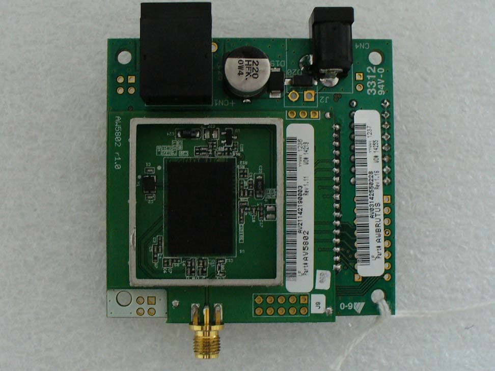
R4N-AW5802MR
Dec 17, 2012AW5802MR
Equipment Class
DTS - Digital Transmission System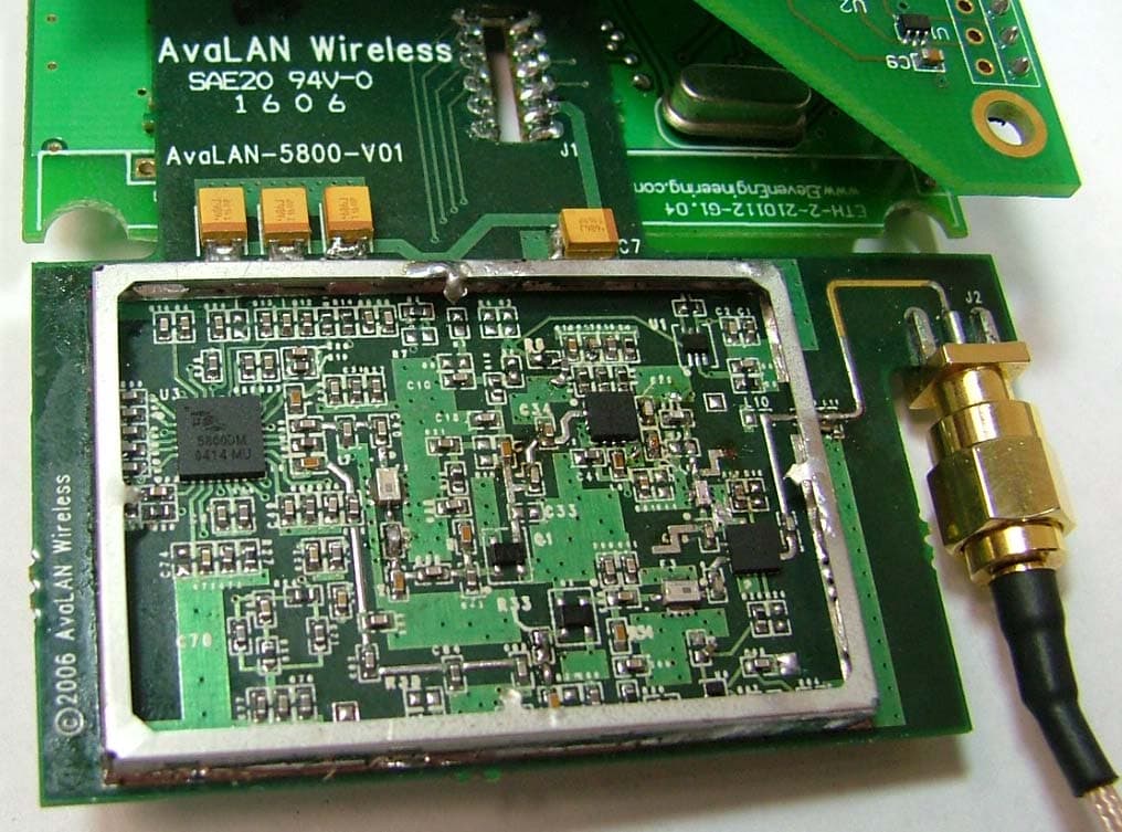
R4N-AW5800M
Jul 19, 20065.8GHz Wireless Ethernet Bridge Module
Equipment Class
DTS - Digital Transmission System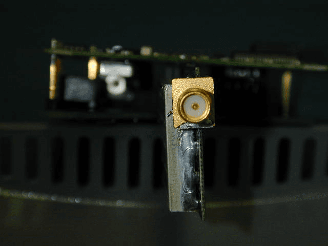
R4N-AW900M
Sep 08, 2005Ethernet Bridge Transmitter Module
Equipment Class
DTS - Digital Transmission System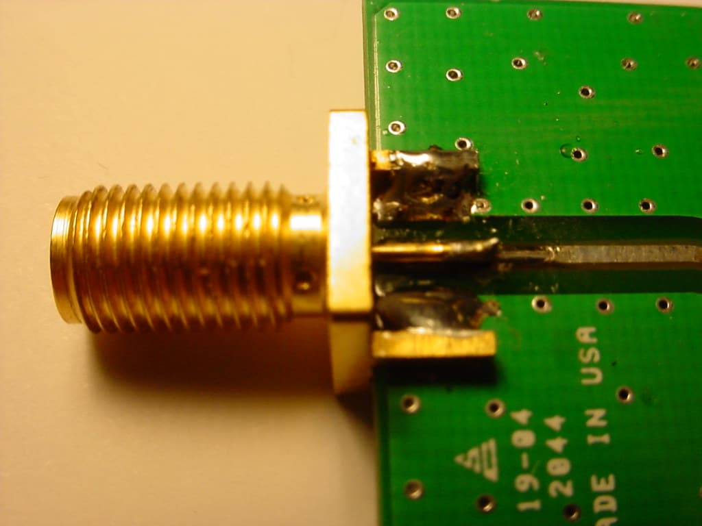
R4N-AW900
Oct 28, 2004Digital Spread Spectrum
Equipment Class
DTS - Digital Transmission System