R4N-AW900MEthernet Bridge Transmitter Module
Avalan Wireless Systems Incorporated
Click to zoom
Application Details
- Equipment Class
- DTS - Digital Transmission System
- Date of Grant
- Sep 08, 2005
- Application Purpose
- Original Equipment
- Date of Application
- Sep 08, 2005
- Equipment Note
- Ethernet Bridge Transmitter Module
- Frequency Range
- 902.00000000 - 928.00000000
- Country
- United States
Documents & Files
Document Text
Text extracted from the exhibit documents filed with the FCC. Open a document above to read the original.
Users Manual
AW900m User’s Manual Thank you for your purchase of the AW900m Module. If you have any questions when configuring your AvaLAN module, please send us an email: [email protected] Quick Setup for systems using the AW900m Module: 1. Attach an RPSMA 900MHz antenna to each module. 2. Plug in the AW900m module. 3. Connect an Ethernet cable from each AW900m to a network device. 4. Send Ethernet traffic. For troubleshooting see page 2. Each AW900m radio automatically selects the best radio channel, encrypts the Ethernet traffic and transports the data wirelessly to its mate. AW900m Ethernet RJ45 Power 9VDC AW900m Ethernet RJ45 Power 9VDC 900 MHz Radio Ethernet Bridge Any Ethernet device can be connected to the AW900m. The AW900m functions in place of an Ethernet cable and provides a transparent wireless point to point Ethernet cable replacement. Cross-over cables are not necessary as the AW900m automatically senses the device (client or switch. LED display: The AW900m has a 16 LED display to display the status of the device. LED Name Function Color 1 Power Unit has power and has successfully booted. Red 2 RF Link The radio has successfully linked with it partner. Green 3 RF TX Radio transmission is occurring. Green 4 RF RX Radio reception is occurring. Green 5 Eth Link The Ethernet Port has a valid Ethernet connection Green 6 Activity The AW900m is processing data Green 7 1 (channel) 8 2 (channel) 9 4 (channel) 10 8 (channel) By adding the numbers that are lit the user can determine the current radio channel. 1 903 MHz 7 915 MHz 2 905 MHz 8 917 MHz 3 907 MHz 9 919 MHz 4 909 MHz 10 921 MHz 5 911 MHz 11 923 MHz 6 913 MHz 12 925 MHz Green 11 Link Quality Excellent link quality – No retransmissions Green 12 Link Quality Very good link quality – Few retransmissions Green 13 Link Quality Good link quality – Occasional retransmissions Amber 14 Link Quality Fair link quality – Some retransmissions Amber 15 Link Quality Poor link quality – Many retransmissions Red 16 Link Quality No link quality No link available Red Troubleshooting: See the online installation tutorial and FAQ at www.avalanwireless.com No Power LED: Check the power connections. No Radio Link LED: The radio is looking for its matched partner. If both units are powered up and the Power LEDs are active they may be too far away to create the radio connection. Try other locations that may have a less obstructed path or try to reorient the antennas. Yagi type antennas get their best range when they are oriented to point directly at each other with the antenna elements oriented in the same plane (eg. vertically or horizontally) Radio LINK LED on but Link Quality Indicator is low: The units may be too far away to create a good radio connection. Try other locations that may have a less obstructed path or try to reorient the antennas. No Ethernet LINK LED: Check your network connections. Installing Multiple systems in close proximity: See the online installation tutorial and FAQ at www.avalanwireless.com Still not working? Temporarily use an Ethernet cable to see if the network is working over a wired connection. If an Ethernet cable does not work then the problem is with the network. Support Email: [email protected] Support helpline: (650) 384-0000 Advanced Settings: Automatic frequency selection mode (DIP switches – all OFF for automatic mode) The AW900m is designed to automatically select and continuously optimize the performance of its radio channel. The radio channel is monitored to ensure it is providing low error rates necessary for successful radio transmission. In the event that the error rate rises, the AW900m will autonomously change to a new channel. There are 12 non-overlapping channels. Manual frequency selection mode To restrict the operation of the AW900m to a subset of the 902-928 band, the user may activate a manual selection mode that allows the radio to automatically choose the best channel within a grouped subset of the 12 available channels. This is enabled by the 8 position DIP switch on the master unit. These settings allow the AW900m to operate on the optimal channel in one of three subsets, LOW 4, MID 4 or HIGH 4. The DIP switch setting are: Channels DIP Setting Frequency LOW 4 - 1,2,3 or 4 2 On / 3 Of f 903-909 MHz MID 4 - 5,6,7 or 8 2 Off / 3 On 911-917 MHz HIGH 4 - 9,10,11 or 12 2 On / 3 On 919-925 MHz Or - the user may wish to select a specific channel. This can be done by setting DIP switches 5-8 as shown in the table below. [Turn DIP 2 Off / 3 Off] Channel DIP Setting Frequency 1 5 On / 6 Off / 7 Off / 8 O ff 903 MHz 2 5 Off / 6 On / 7 Off / 8 Off 905 MHz 3 5 On / 6 On / 7 Off / 8 Off 907 MHz 4 5 Off / 6 Off / 7 On / 8 Off 909 MHz 5 5 On / 6 Off / 7 On / 8 Off 911 MHz 6 5 Off / 6 On / 7 On / 8 Off 913 MHz 7 5 On / 6 On / 7 On / 8 Off 915 MHz 8 5 Off / 6 Off / 7 Off / 8 On 917 MHz 9 5 On / 6 Off / 7 Off / 8 On 919 MHz 10 5 Off / 6 On / 7 Off / 8 On 921 MHz 11 5 On / 6 On / 7 Off / 8 On 923 MHz 12 5 Off / 6 Off / 7 On / 8 On 925 MHz Site survey mode (DIP switch 4 - default is OFF for normal operation) In this mode the AW900m can perform a site survey. With this mode activated the radios send and receive at 100% capacity by transceiving self-generated simulated data. The installer can monitor the Link Quality display to assess channel quality while optimizing antennae orientation. The installer can manually select each channel to evaluate performance and identify the best channels for operation. By identifying channels with poor performance it is possible to identify possible interferers and use “manual frequency selection mode” to avoid portions of the band or select a fixed operating frequency. Important note: Ethernet traffic does not get transported while the radios are in this mode. Technical Specifications: (typical) Characteristic Specification - description RF transmission rate: 1.5 Mb/s Throughput: 935 Kb/s Output power: +21dBm – (4 Watts EIRP with 15dBi antennae) Receive sensitivity: -97dBm …
Text truncated - open the document above for the full version.
Cover Letter(s)
2400 El Camino Real #317, Mountain View, CA, 94040 –T (650) 444 5117 – F (650) 249 3591 May 27, 2005 To Whom It May Concern: AvaLAN Wireless would like to apply for Modular FCC approval. This letter is our application for such according to FCC public notice DA 00-1407. AW900 Modular Transmitter Requirements Modular Transmitter Requirements Manufacturer Clarification A – In order to be considered a transmitter module, the device must be a complete RF transmitter, i.e., it must have its own reference oscillator (e.g., VCO), antenna, etc. The only connectors to the module, if any, may be the power supply and modulation/data inputs. The transmitter is complete with its own reference oscillator, antenna. The only connectors provided are the DC supply, Data, and RF ports. B – Compliance with FCC RF Exposure requirements may, in some instances, limit the output power of a module and/or the final applications in which the approved module may be employed. The radio complies with MPE per 2.1091 for use with mobile or fixed base stations. C – While the applicant for a device into which an authorized module is installed is not required to obtain a new authorization for the module, this does not preclude the possibility that some other form of authorization or testing may be required for the device (e.g., a WLAN into which an authorized module is installed must still be authorized as a PC peripheral, subject to the appropriate equipment authorization). The equipment complies with FCC Part 15, Subpart B, Class B – Unintentional radiators. D – In the case of a modular transceiver, the modular approval policy only applies to the transmitter portion of such devices. Pursuant to Section 15.101(b), the receiver portion will either be subject to Verification, or it will not be subject to any authorization requirements (unless it is a Scanning Receiver, in which case it is also subject to Certification, pursuant to Section 15.101(a)). The receiver operates in 902-928 MHz and complies with FCC Part 15, Subpart B – Radio Receivers. 2400 El Camino Real #317, Mountain View, CA, 94040 –T (650) 444 5117 – F (650) 249 3591 Modular Transmitter Requirements Manufacturer Clarification E – The holder of the grant of equipment authorization (Grantee) of the module is responsible for the compliance of the module in its final configuration, provided that the OEM, integrator, and/or end user has complied with all of the instructions provided by the Grantee which indicate installation and/or operating conditions necessary for compliance. End users must conform with the following instructions stated in the users’ manual: - Labeling requirement for equipment using this modular transmitter. - RF Exposure information for compliance with FCC Rules 2.1091 or 2.1093 are specified in the user manual for OEM, integrator, and/or end user. 1. The modular transmitter must have its own RF shielding. This is intended to ensure that the module does not have to rely upon the shielding provided by the device into which it is installed in order for all modular transmitter emissions to comply with Part 15 limits... Such coupling may result in non-compliant operation. The modular transmitter has its own RF shielding. 2. The modular transmitter must have buffered modulation/data inputs (if such inputs are provided) to ensure that the module will comply with Part 15 requirements under conditions of excessive data rates or over-modulation. The modular transmitter has buffered modulation/data inputs. 3. The modular transmitter must have its own power supply regulation. This is intended to ensure that the module will comply with Part 15 requirements regardless of the design of the power supplying circuitry in the device into which the module is installed. The modular transmitter has its own power supply regulation. 4. The modular transmitter must comply with the antenna requirements of Section 15.203 and 15.204c. The antenna must either be permanently attached or employ a “unique” antenna coupler (at all connections between the module and the antenna, including the cable). Any antenna used with the module must be approved with the module; either at the time of initial authorization or through a Class II permissive change. The “professional installation” provision of Section 15.203 may not be applied to modules. The radio complies with Rules 15.203 and 15.204c. The radio may have either a permanently attached wire antenna or a unique antenna coupler (RPSMA or RPTNC) for all other approved antennas. 2400 El Camino Real #317, Mountain View, CA, 94040 –T (650) 444 5117 – F (650) 249 3591 Modular Transmitter Requirements Manufacturer Clarification 5. The modular transmitter must be tested in a stand-alone configuration, i.e., the module must not be inside another device during testing. This is intended to demonstrate that the module is capable of complying with Part 15 emission limits regardless of the device into which it is eventually installed... The modular transmitter was tested in a stand-alone configuration. 6. The modular transmitter must be labeled with its own FCC ID number, and, if the FCC ID is not visible when the module is installed inside another device, then the outside of the device into which the module is installed must also display a label referring to the enclosed module... The modular transmitter is labeled with its own FCC ID number. The label is fixed on the shield. 7. The modular transmitter must comply with any specific rule or operating requirements applicable to the transmitter and the manufacturer must provide adequate instructions along with the module to explain any such requirements. The user manual for the AW900 contains adequate instructions relating to the usage, approved antennas, and power supply requirements of the modular transmitter. 8. The modular transmitter must comply with any applicable RF exposure requirements. The modular transmitter was tested to applicable RF exposure requirements. Sincerely, Michael R De…
Text truncated - open the document above for the full version.
Cover Letter(s)
AvaLAN Wireless Systems Incorporated 2400 El Camino Real #317 Mountain View, CA 94040 T 650 444 5117 F 650 249 3591 Federal Communications Commission 7435 Oakland Mills Road Columbia, MD 21046 USA Authority to Act as Agent to the Federal Communications Commission On our behalf, I appoint NEMKO Dallas, Inc. to act as agent in the preparation of this application for equipment authorization to the Federal Communications Commission. I certify that submitted Exhibits properly describe the device or system for which equipment authorization is sought. I also certify that each unit manufactured, imported or marketed, as defined in the Commission's regulations will have affixed to it a label identical to that submitted for approval with this application. APPLICANT ANTI-DRUG ABUSE CERTIFICATION: In signing this letter, Applicant certifies that, in the case of an individual applicant, he or she is not subject to a denial of federal benefits, that includes FCC benefits, pursuant to Section 5301 of the Anti-Drug Abuse Act of 1988, 21 U.S.C. 853(a), or, in the case of a non-individual applicant (e.g. corporation, partnership or other unincorporated association), no party to the application is subject to a denial of federal benefits, that includes FCC benefits, pursuant to that section. For the definition of a "party" for these purposes, see 47 CFR 1.2002(b). November 11, 2004 Agency agreement expiration date: By: Michael R Derby Title: CTO Telephone:650 444 5117 Applicant: AvaLAN Wireless Systems Incorporated
Cover Letter(s)
September 9, 2005 Equipment Authorisation Division Federal Communications Commission 7435 Oakland Mills Road Columbia, MD 21046 FCC ID: R4N-AW900M Product Name: AW900M Request for Confidentiality Pursuant to Sections 0.457 and 0.459 of the commissions rules, we hereby request that the following documents be held confidential: • Schematics • Block diagram • Operational description These materials contain trade secrets and proprietary information and are not customarily released to the public. The public disclosure of this information might be harmful to the company and provide unjustified benefits to our competitors. Dated this 9 TH Day of September 20 05 By: Michael R. Derby Signature Printed Title: President On behalf of : AvaLan Wirleless Telephone: 866-533-6216
Internal Photos
AvaLAN Photos
RF Exposure Info
Prediction of MPE limit at a given distance Equation from page 18 of OET Bulletin 65, Edition 97-01 where:S = power density P = power input to the antenna G = power gain of the antenna in the direction of interest relative to an isotropic radiator R = distance to the center of radiation of the antenna Maximum peak output power at antenna input terminal:20.91(dBm) Maximum peak output power at antenna input terminal:123.3104833(mW) Antenna gain(typical):15(dBi) Maximum antenna gain:31.6227766(numeric) Time Averaging:58(%)(58ms in 100) Prediction distance:20(cm) Prediction frequency:928(MHz) MPE limit for uncontrolled exposure at prediction frequency:0.6(mW/cm^2) Power density at prediction frequency:0.449944(mW/cm^2) Margin of compliance:-1.2(dB) 2 4R PG S π =
Test Report
Nemko Test Report: 4L0715RUS1Rev2 Applicant: AvaLAN WirelessSystems, Inc. 2400 El Camino Real Suite 317 Mountain View, CA 94040 Equipment Under Test: AW900 Wireless Ethernet Link (E.U.T.) FCC ID: R4N-AW900 In Accordance With: FCC Part 15, Subpart C, 15.247 Tested By: Nemko Dallas Inc. 802 N. Kealy Lewisville, Texas 75057-3136 Authorized By: Tom Tidwell, Frontline Group Manager Date: 13 Dec. 2004 Nemko Dallas FCC PART 15, SUBPART C DIRECT SEQUENCE SPREAD SPECTRUM TRANSMITTER EQUIPMENT: AW900 Wireless Ethernet Link PROJECT NO.:4L0715RUS1Rev2 Page 2 of 14 Table of Contents Section 1. Summary of Test Results .................................................................3 Section 2. Equipment Under Test (E.U.T.) ......................................................5 Section 3. Spurious Emissions (Restricted Bands) .........................................6 Section 4. Test Equipment List ......................................................................... 10 ANNEX A - TEST DETAILS............................................................................. 11 ANNEX B - TEST DIAGRAMS ........................................................................ 13 Nemko Dallas FCC PART 15, SUBPART C DIRECT SEQUENCE SPREAD SPECTRUM TRANSMITTER EQUIPMENT: AW900 Wireless Ethernet Link PROJECT NO.:4L0715RUS1Rev2 Page 3 of 14 Section 1. Summary of Test Results Manufacturer: AvaLAN Wireless Systems, Inc. Model No.: AW900 ver2 Serial No.: 000022 General: All measurements are traceable to national standards. These tests were conducted on a sample of the equipment for the purpose of demonstrating compliance with Part 15, Subpart C, Paragraph 15.247 for Direct Sequence Spread Spectrum devices. Radiated tests were conducted is accordance with ANSI C63.4-2004. Radiated emissions are made on an open area test site. A description of the test facility is on file with the FCC. New Submission Production Unit Class II Permissive Change Pre-Production Unit THIS TEST REPORT RELATES ONLY TO THE ITEM(S) TESTED. THE FOLLOWING DEVIATIONS FROM, ADDITIONS TO, OR EXCLUSIONS FROM THE TEST SPECIFICATIONS HAVE BEEN MADE. NONE NVLAP LAB CODE: 100426-0 Nemko Dallas Inc. authorizes the above named company to reproduce this report provided it is reproduced in its entirety and for use by the company’s employees only. Any use which a third party makes of this report, or any reliance on or decisions to be made based on it, are the responsibility of such third parties. Nemko Dallas Inc. accepts no responsibility for damages, if any, suffered by any third party as a result of decisions made or actions based on this report. This report applies only to the items tested. Nemko Dallas FCC PART 15, SUBPART C DIRECT SEQUENCE SPREAD SPECTRUM TRANSMITTER EQUIPMENT: AW900 Wireless Ethernet Link PROJECT NO.:4L0715RUS1Rev2 Page 4 of 14 Summary Of Test Data NAME OF TEST PARA. NO. SPEC. RESULT Powerline Conducted Emissions 15.207(a) 48 dBμV NA Minimum 6 dB Bandwidth 15.247(a)(2) >500 kHz NA Maximum Peak Power Output 15.247(b)(1)<1 Watt NA Spurious Emissions (Antenna Conducted) 15.247(c) -20 dBc/100kHz NA Spurious Emissions (Restricted Bands) 15.247(c) < 74 dBuV/m Peak < 54 dBuV/m Avg COMPLIES Peak Power Spectral Density 15.247(d) +8 dBm/3kHz NA Footnotes: The change being made for Class II is to include a new antenna, therefore radiated emissions in the restricted bands was the only testing performed. Nemko Dallas FCC PART 15, SUBPART C DIRECT SEQUENCE SPREAD SPECTRUM TRANSMITTER EQUIPMENT: AW900 Wireless Ethernet Link PROJECT NO.:4L0715RUS1Rev2 Page 5 of 14 Section 2. Equipment Under Test (E.U.T.) General Equipment Information Frequency Band: 902 to 928 MHz Description of Modification for Modification Filing A 15 dBi gain Yagi antenna is now being offered for extended coverage outdoors. Operational Description The AvaLAN Wireless Systems AW900 is designed to operate as a plug-and-play high speed wireless Ethernet link. The AW900 operates as a 900 MHz digital spread spectrum link with data rates as high as 1.5 Mb/s, making it an ideal replacement for traditional wired DSL/TI internet connections, as well as other high data rate secure communication applications. The AW900 is typically used in pairs, and is powered by a standard wall type transformer supplying 6.0 VDC @ 500 mA. The AW900 is equipped with an ‘RJ-45’ type jack as the data access port, and uses a “Nearson” model S467AH-915S whip antenna or a 15 dBi Yagi. Nemko Dallas FCC PART 15, SUBPART C DIRECT SEQUENCE SPREAD SPECTRUM TRANSMITTER EQUIPMENT: AW900 Wireless Ethernet Link PROJECT NO.:4L0715RUS1Rev2 Page 6 of 14 Section 3. Spurious Emissions (Restricted Bands) NAME OF TEST: Spurious Emissions (Restricted Bands) PARA. NO.: 15.247 (c) TESTED BY: David Light DATE: 12/6/04 Test Results: Complies. Measurement Data: See attached table. Duty Cycle Calculation: Duty Cycle correction factor(dB) = 20 log (rf ON in ms/100ms) On time in 100 msec. = 57.6 msec. 20 log (57/100) = -4.8 dB Equipment Used: 1484-1485-1304-1464-1016-1983-791-759-760 Measurement Uncertainty: +/- 3.6 dB Temperature: 22 °C Relative Humidity: 45 % Nemko Dallas FCC PART 15, SUBPART C DIRECT SEQUENCE SPREAD SPECTRUM TRANSMITTER EQUIPMENT: AW900 Wireless Ethernet Link PROJECT NO.:4L0715RUS1Rev2 Page 7 of 14 Radiated Data Low channel Page 1 of 3 Job No.:4L0715Date: 12/6/2004 Specification:15.247/15.205Temperature(°C): 22 Tested By:David LightRelative Humidity(%) 45 E.U.T.: Configuration: Sample Number:1 Location:AC 3RBW:1 MHz Detector Type:PeakVBW:1 MHz Antenna:1304Directional Coupler:#N/A Pre-Amp:1016Cable #1:1484 Filter:1481Cable #2:1485 Receiver:1036Cable #3:#N/A Attenuator #1#N/ACable #4:#N/A Attenuator #2:#N/AMixer:#N/A Measurement Uncertainty: +/- 3.6 dB Meter Reading (dBuV) Antenna Factor (dB) Cable Loss (dB) Corrected Reading (dBuV/m) Detector / Polarity 2.70958.329.03.632.758.27454P eak / Vertical 2.70953.529.03.632.753.47454Average / Vertical 3.61252.530.73.632.454.47454P eak / Vertical 3.61247.730.73.632.449.67454…
Text truncated - open the document above for the full version.
Test Report
L.S. Compliance, Inc. W66 N220 Commerce Court Cedarburg, WI 53012 262-375-4400 Fax: 262-375-4248 COMPLIANCE TESTING OF : AW900 Wireless Ethernet Link Prepared For: AvaLAN Wireless Systems, Inc. Attention: Mr. Mike Derby 2400 El Camino Real Suite 317 Mountain View, CA 94040 Test Report Number: 304224 TX TCB Rev. 1 Test Dates: May 5 th -26 th , 2004 All results of this report relate only to the items that were tested. This report is not to be reproduced, except in full, without written approval of L. S. Compliance, Inc. L.S. Compliance, Inc. Page 2 of 37 Test Report Number: 304224 TX TCB Rev. 1 Prepared For: AvaLAN Wireless Systems, Inc. Table of Contents Section Description Page Index 2 1 L. S. Compliance in Review 3 2 A2LA Certificate of Accreditation 4 3 A2LA Scope of Accreditation 5 4 Validation Letter-U.S. Competent Body for EMC Directive 89/336/EEC 6 5 Signature Page 7 6 Product and General Information 8 7 Introduction 8 8 Product Description 8 9 Test Requirements 9 10 Summary of Test Report 9 11 Radiated Emissions Test 10-18 12 Band-Edge Measurements 19 13 Conducted Emissions Test, AC Power Line 20-24 14 Conducted Emissions Test, Power Output 15.247 (b) 25-26 15 Conducted Emissions Test, Spurious Emissions 15.247 (d) 27-30 16 Conducted Emissions Test, Occupied Bandwidth 31-32 17 Conducted Emissions Test, Spectral Density 33-34 18 MPE Calculations 35 Appendix A Test Equipment List 36 B Antenna Specifications 37 L.S. Compliance, Inc. Page 3 of 37 Test Report Number: 304224 TX TCB Rev. 1 Prepared For: AvaLAN Wireless Systems, Inc. 1. L. S. Compliance In Review L.S. Compliance – Accreditations and Listing’s As an EMC Testing Laboratory, our Accreditation and Assessments are recognized through the following: A2LA – American Association for Laboratory Accreditation Accreditation based on ISO/IEC 17025 : 1999 with Electrical (EMC) Scope of Accreditation A2LA Certificate Number: 1255.01 Federal Communications Commission (FCC) – USA Listing of 3 Meter Semi-Anechoic Chamber based on Title 47 CFR – Part 2.948 FCC Registration Number: 90756 Listing of 3 and 10 meter OATS based on Title 47CFR – Part 2.948 FCC Registration Number: 90757 Industry Canada On file, 3 Meter Semi-Anechoic Chamber based on RSS-212 – Issue 1 File Number: IC 3088-A On file, 3 and 10 Meter OATS based on RSS-212 – Issue 1 File Number: IC 3088 U. S. Conformity Assessment Body (CAB) Validation Validated by the European Commission as a U. S. Competent Body operating under the U. S. /EU, Mutual Recognition Agreement (MRA) operating under the European Union Electromagnetic Compatibility –Council Directive 89/336/EEC, Article 10.2. Date of Validation: January 16, 2001 Validated by the European Commission as a U.S. Notified Body operating under the U.S./EU, Mutual Recognition Agreement (MRA) operating under the European Union Telecommunication Equipment – Council Directive 99/5/EC, Annex V. Date of Validation: November 20, 2002 Notified Body Identification Number: 1243 L.S. Compliance, Inc. Page 4 of 37 Test Report Number: 304224 TX TCB Rev. 1 Prepared For: AvaLAN Wireless Systems, Inc. 2. A2LA Certificate of Accreditation L.S. Compliance, Inc. Page 5 of 37 Test Report Number: 304224 TX TCB Rev. 1 Prepared For: AvaLAN Wireless Systems, Inc. 3. A2LA Scope of Accreditation L.S. Compliance, Inc. Page 6 of 37 Test Report Number: 304224 TX TCB Rev. 1 Prepared For: AvaLAN Wireless Systems, Inc. 4. Validation Letter – U.S. Competent Body for EMC Directive 89/336/EEC L.S. Compliance, Inc. Page 7 of 37 Test Report Number: 304224 TX TCB Rev. 1 Prepared For: AvaLAN Wireless Systems, Inc. 5. Signature Page Prepared By: October 25, 2004 Teresa A. White, Document Coordinator Date Tested By: October 25, 2004 Abtin Spantman, EMC Engineer Date Approved By: October 25, 2004 Kenneth L. Boston, EMC Lab Manager Date PE #31926 Licensed Professional Engineer Registered in the State of Wisconsin, United States L.S. Compliance, Inc. Page 8 of 37 Test Report Number: 304224 TX TCB Rev. 1 Prepared For: AvaLAN Wireless Systems, Inc. 6. Product and General Information Manufacturer: AvaLAN Wireless Systems, Inc. Date(s) of Test: May 5 th – 26 th , 2004 Test Engineer(s): Tom Smith √ Abtin Spantman Ken Boston Model #: AW900 Serial #: M258 Voltage: 6.0 VDC, 50mA Operation Mode: Normal 7. Introduction Between August 9 th to August 26 th , 2004, a series of Conducted and Radiated Emission tests were performed on one sample of the AvaLAN Wireless Systems AW 900 Wireless Ethernet Link, here forth referred to as the “Equipment Under Test” or “EUT”. These tests were performed using the procedures outlined in ANSI C63.4-2003 for intentional radiators, and in accordance with the limits set forth in FCC Part 15.247 (Industry Canada RSS-210) for a low power transmitter. These tests were performed by Abtin Spantman, EMC Engineer of L.S. Compliance, Incorporated. All Radiated and Conducted Emission tests were performed upon the EUT to measure the emissions in the frequency bands described in Title 47 CFR, FCC Part 15, including 15.35, 15.209, 15.247 and Industry Canada RSS-210 to determine whether these emissions are below the limits expressed within the standards. These tests were performed in accordance with the procedures described in the American National Standard for methods of measurement of Radio- Noise Emissions from Low-Voltage Electrical and Electronic Equipment in the Range of 9 kHz to 40 GHz (ANSI C63.4-2003). Another document used as a reference for the EMI Receiver specification was the Comite International Special Des Perturbations Radioelelectriques (CISPR) Number 16-1, 2003. All tests were performed at L.S. Compliance, Inc., in Cedarburg, Wisconsin, unless otherwise noted. 8. Product Description The AvaLAN Wireless Systems AW900 is designed to operate as a plug-and-play high speed wireless Ethernet link. The AW900 operates as a 900 MHz digital spread spectrum link with data rates as high as 1.5 Mb/s, making it an ideal replacement for traditional wired DSL/TI…
Text truncated - open the document above for the full version.
Test Report
Nemko Test Report: 4L0715RUS1Rev4 Applicant: AvaLAN WirelessSystems, Inc. 2400 El Camino Real Suite 317 Mountain View, CA 94040 Equipment Under Test: AW900 Wireless Ethernet Link (E.U.T.) FCC ID: R4N-AW900M In Accordance With: FCC Part 15, Subpart C, 15.247 Tested By: Nemko Dallas Inc. 802 N. Kealy Lewisville, Texas 75057-3136 Authorized By: Tom Tidwell, Frontline Group Manager Date: 27 August, 2005 Nemko Dallas FCC PART 15, SUBPART C DIRECT SEQUENCE SPREAD SPECTRUM TRANSMITTER EQUIPMENT: AW900 Wireless Ethernet Link PROJECT NO.:4L0715RUS1Rev4 Page 2 of 14 Table of Contents Section 1. Summary of Test Results .....................................................................3 Section 2. Equipment Under Test (E.U.T.) ...........................................................5 Section 3. Spurious Emissions (Restricted Bands) ...............................................6 Section 4. Test Equipment List ...............................................................................12 ANNEX A - TEST DETAILS .................................................................................13 ANNEX B - TEST DIAGRAMS.............................................................................15 Nemko Dallas FCC PART 15, SUBPART C DIRECT SEQUENCE SPREAD SPECTRUM TRANSMITTER EQUIPMENT: AW900 Wireless Ethernet Link PROJECT NO.:4L0715RUS1Rev4 Page 3 of 14 Section 1. Summary of Test Results Manufacturer: AvaLAN Wireless Systems, Inc. Model No.: AW900 ver2 Serial No.: 00013 General: All measurements are traceable to national standards. These tests were conducted on a sample of the equipment for the purpose of demonstrating compliance with Part 15, Subpart C, Paragraph 15.247 for Direct Sequence Spread Spectrum devices. Radiated tests were conducted is accordance with ANSI C63.4-2003. Radiated emissions are made on an open area test site. A description of the test facility is on file with the FCC. New Submission Production Unit Class II Permissive Change Pre-Production Unit THIS TEST REPORT RELATES ONLY TO THE ITEM(S) TESTED. THE FOLLOWING DEVIATIONS FROM, ADDITIONS TO, OR EXCLUSIONS FROM THE TEST SPECIFICATIONS HAVE BEEN MADE. NONE NVLAP LAB CODE: 100426-0 Nemko Dallas Inc. authorizes the above named company to reproduce this report provided it is reproduced in its entirety and for use by the company’s employees only. Any use which a third party makes of this report, or any reliance on or decisions to be made based on it, are the responsibility of such third parties. Nemko Dallas Inc. accepts no responsibility for damages, if any, suffered by any third party as a result of decisions made or actions based on this report. This report applies only to the items tested. Nemko Dallas FCC PART 15, SUBPART C DIRECT SEQUENCE SPREAD SPECTRUM TRANSMITTER EQUIPMENT: AW900 Wireless Ethernet Link PROJECT NO.:4L0715RUS1Rev4 Page 4 of 14 Summary Of Test Data NAME OF TEST PARA. NO. SPEC. RESULT Powe…
Text truncated - open the document above for the full version.
Contact Information
Applicant
Michael R Derby(CTO)
Technical Contact
Nemko USA IncTom Tidwell
[email protected]972 436 9600
802 N. Kealy · Lewisville, Texas · United States
Non-Technical Contact
Nemko Usa IncTom Tidwell
[email protected]972 436 9600
Test Firm
Nemko Dallas, Inc.Michael Cantwell
Technical Specifications
| # | Rule Parts | Frequency Range | Power Output |
|---|---|---|---|
| 1 | 15C | 902 MHz - 928 MHz | 123.00 mW |
Other Applications from Avalan Wireless Systems Incorporated
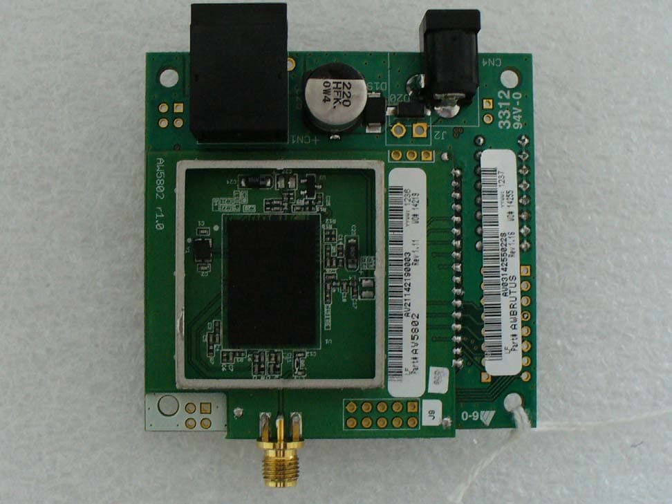
R4N-AW5802MR
Dec 17, 2012AW5802MR
Equipment Class
DTS - Digital Transmission System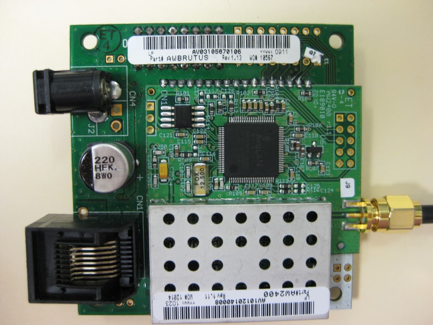
R4N-AW2400MR
Nov 08, 20102.4 GHz Wireless Ethernet Module
Equipment Class
DTS - Digital Transmission System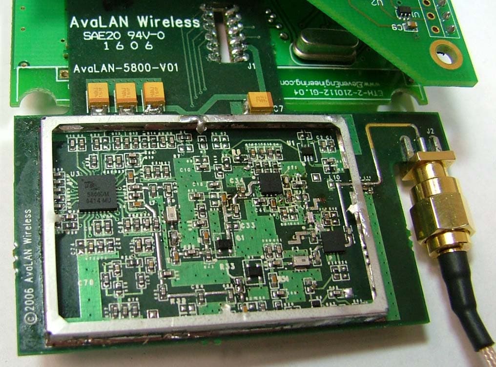
R4N-AW5800M
Jul 19, 20065.8GHz Wireless Ethernet Bridge Module
Equipment Class
DTS - Digital Transmission System
R4N-AW900
Oct 28, 2004Digital Spread Spectrum
Equipment Class
DTS - Digital Transmission System