R4N-AW5800M5.8GHz Wireless Ethernet Bridge Module
Avalan Wireless Systems Incorporated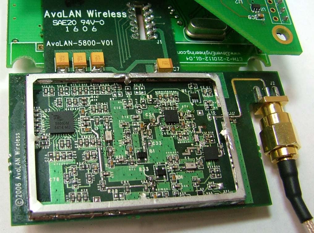
Click to zoom
Application Details
- Equipment Class
- DTS - Digital Transmission System
- Date of Grant
- Jul 19, 2006
- Application Purpose
- Original Equipment
- Date of Application
- Jul 19, 2006
- Equipment Note
- 5.8GHz Wireless Ethernet Bridge Module
- Frequency Range
- 5728.12500000 - 5846.87500000
- Country
- United States
Documents & Files
Document Text
Text extracted from the exhibit documents filed with the FCC. Open a document above to read the original.
Users Manual
AW5800m-SR Module Integrator’s Kit User’s Manual Thank you for your purchase of the AW5800m-SR Module. If you have any questions when configuring your AvaLAN module please send us an email: [email protected] Kit Contents: 2 AW5800m-SR RF Modules (RPSMA female) 2 AWP12 12in Pigtails (RPSMA inline male to RPTNC bulkhead female) Quick Setup for systems using the AW5800m Module: 1. Attach a 5800MHz antenna to each module. (see AW5-5800, AW23-5800) 2. Apply power to the AW5800m module. 3. Connect an Ethernet cable from each AW5800m to a network device. 4. Send Ethernet traffic. For troubleshooting see page 2. Each AW5800m radio automatically selects the best radio channel, encrypts the Ethernet traffic and transports the data wirelessly to its mate. Any Ethernet device can be connected to the AW5800m. The AW5800m functions in place of an Ethernet cable and provides a transparent wireless point to point Ethernet cable replacement. Cross- over cables are not necessary as the AW5800m automatically senses the device (client or switch). AW5800m-SR Ethernet RJ45 Power 5.8GHz Radio Ethernet Bridge AW5800m- Ethernet RJ45 Power AW5800m-SR Power Ethernet 10BT RF Antenna AW5800m-SR Power Ethernet 10BT RF Antenna Up to 50 Miles 1.536 Mb/sec Application diagram: 40 Mile wireless network surveillance camera System Diagram: Power, Data, DIPs, LEDs and RF Interfaces: Power Jack P5/2.1mm Center Positive 4.5-48VDC Power over Ethernet Lines 4/5 Positive Lines 7/8 Ground 9-48VDC Power Terminal 12-24VAC or 6-48VDC Polarity is auto corrected. RF RPSMA Female +20dBm out put DATA 10BT Ethernet Lines 1/2/3/6 AutoMDIX correction DIP Switch 8 Pin DIP LED Display 16 LEDs LED display: The AW5800m has a 16 LED display to display the status of the device. LED Name Function Color 1 Power Unit has power and has successfully booted. Red 2 RF TX Radio transmission is occurring. Green 3 RF RX Radio reception is occurring. Green 4 Eth Link The Ethernet Port has a valid Ethernet connection Green 5 1 (channel) 6 2 (channel) 7 4 (channel) 8 8 (channel) 9 16 (channel) 10 32 (channel) By adding the values that are lit, the user can determine the current radio channel. 1 5728.125 Mhz 2 5730.208 Mhz 3 5732.292 Mhz 4 5734.375 Mhz 5 5736.458 Mhz 6 5738.542 Mhz 7 5740.625 Mhz 8 5742.708 Mhz 9 5744.792 Mhz 10 5746.875 Mhz 11 5748.958 Mhz 12 5751.042 Mhz 13 5753.125 Mhz 14 5755.208 Mhz 15 5757.292 Mhz 16 5759.375 Mhz 17 5761.458 Mhz 18 5763.542 Mhz 19 5765.625 Mhz 20 5767.708 Mhz 21 5769.792 Mhz 22 5771.875 Mhz 23 5773.958 Mhz 24 5776.042 Mhz 25 5778.125 Mhz 26 5780.208 Mhz 27 5782.292 Mhz 28 5784.375 Mhz 29 5786.458 Mhz 30 5788.542 Mhz 31 5790.625 Mhz 32 5792.708 Mhz 33 5794.792 Mhz 34 5796.875 Mhz 35 5798.958 Mhz 36 5801.042 Mhz 37 5803.125 Mhz 38 5805.208 Mhz 39 5807.292 Mhz 40 5809.375 Mhz 41 5811.458 Mhz 42 5813.542 Mhz 43 5815.625 Mhz 44 5817.708 Mhz 45 5819.792 Mhz 46 5821.875 Mhz 47 5823.958 Mhz 48 5826.042 Mhz 49 5828.125 Mhz 50 5830.208 Mhz 51 5832.292 Mhz 52 5834.375 Mhz 53 5836.458 Mhz 54 5838.542 Mhz 55 5840.625 Mhz 56 5842.708 Mhz 57 5844.792 Mhz 58 5846.875 Mhz Green 11 Link Quality Meter Excellent link quality – No retransmissions Green 12 Link Quality Meter Very good link quality – Few retransmissions Green 13 Link Quality Meter Good link quality – Occasional retransmissions Amber 14 Link Quality Meter Fair link quality – Some retransmissions Amber 15 Link Quality Meter Poor link quality – Many retransmissions Red 16 Link Quality Meter No link quality No link available Red Troubleshooting: See the online installation tutorial and FAQ at www.avalanwireless.com No Power LED: Check the power connections. No Radio Link LED: The radio is looking for its matched partner. If both units are powered up and the Power LEDs are active they may be too far away to create the radio connection. Try other locations that may have a less obstructed path or try to reorient the antennas. Directional antennas get their best range when they are oriented to point directly at each other with the antenna elements oriented in the same plane (eg. vertically or horizontally) Radio LINK LED on but Link Quality Indicator is low: The units may be too far away to create a good radio connection. Try other locations that may have a less obstructed path or try to reorient the antennas. No Ethernet LINK LED: Check your network connections. Installing Multiple systems in close proximity: See the online installation tutorial and FAQ at www.avalanwireless.com Still not working? Temporarily use an Ethernet cable to see if the network is working over a wired connection. If an Ethernet cable does not work then the problem is with the network. Support Email: [email protected] Support helpline: (650) 384-0000 Advanced Settings: Automatic frequency selection mode (DIP switches – all OFF for automatic mode) The AW5800m is designed to automatically select and continuously optimize the performance of its radio channel. The radio channel is monitored to ensure it is providing low error rates necessary for successful radio transmission. In the event that the error rate rises, the AW5800m will autonomously change to a new channel. There are 58 non-overlapping channels. Manual frequency selection mode This mode enables the user to restrict the operation of the AW5800m to a specific channel. This can be done by setting DIP switches 3-8 as shown in the table below. DIP 3DIP 4DIP 5DIP 6DIP 7DIP 8 Add 1Add 2Add 4Add 8Add 16Add 32 0 1 x 5728.1250 Mhz 2x5730.2083 Mhz 3xx5732.2917 Mhz 4x5734.3750 Mhz 5xx5736.4583 Mhz 6xx5738.5417 Mhz 7xxx5740.6250 Mhz 8x5742.7083 Mhz 9xx5744.7917 Mhz 10xx5746.8750 Mhz 11xxx5748.9583 Mhz 12xx5751.0417 Mhz 13xxx5753.1250 Mhz 14xxx5755.2083 Mhz 15xxxx5757.2917 Mhz 16x5759.3750 Mhz 17xx5761.4583 Mhz 18xx5763.5417 Mhz 19xxx5765.6250 Mhz 20xx5767.7083 Mhz 21xxx5769.7917 Mhz 22xxx5771.8750 Mhz 23xxxx5773.9583 Mhz 24xx5776.0417 Mhz 25xxx5778.1250 Mhz 26xxx5780.2083 Mhz 27xxxx5782.2917 Mhz 28xxx5784.3750 Mhz 29xxxx5786.4583 Mhz 30xxxx5788.5…
Text truncated - open the document above for the full version.
Users Manual
AW5800m-SR Module Integrator’s Kit User’s Manual Thank you for your purchase of the AW5800m-SR Module. If you have any questions when configuring your AvaLAN module please send us an email: [email protected] Kit Contents: 2 AW5800m-SR RF Modules (RPSMA female) 2 AWP12 12in Pigtails (RPSMA inline male to RPTNC bulkhead female) Quick Setup for systems using the AW5800m Module: 1. Attach a 5800MHz antenna to each module. (see AW5-5800, AW23-5800) 2. Apply power to the AW5800m module. 3. Connect an Ethernet cable from each AW5800m to a network device. 4. Send Ethernet traffic. For troubleshooting see page 2. Each AW5800m radio automatically selects the best radio channel, encrypts the Ethernet traffic and transports the data wirelessly to its mate. Any Ethernet device can be connected to the AW5800m. The AW5800m functions in place of an Ethernet cable and provides a transparent wireless point to point Ethernet cable replacement. Cross- over cables are not necessary as the AW5800m automatically senses the device (client or switch). AW5800m-SR Ethernet RJ45 Power 5.8GHz Radio Ethernet Bridge AW5800m- Ethernet RJ45 Power AW5800m-SR Power Ethernet 10BT RF Antenna AW5800m-SR Power Ethernet 10BT RF Antenna Up to 50 Miles 1.536 Mb/sec Application diagram: 40 Mile wireless network surveillance camera System Diagram: Power, Data, DIPs, LEDs and RF Interfaces: Power Jack P5/2.1mm Center Positive 4.5-48VDC Power over Ethernet Lines 4/5 Positive Lines 7/8 Ground 9-48VDC Power Terminal 12-24VAC or 6-48VDC Polarity is auto corrected. RF RPSMA Female +20dBm out put DATA 10BT Ethernet Lines 1/2/3/6 AutoMDIX correction DIP Switch 8 Pin DIP LED Display 16 LEDs LED display: The AW5800m has a 16 LED display to display the status of the device. LED Name Function Color 1 Power Unit has power and has successfully booted. Red 2 RF TX Radio transmission is occurring. Green 3 RF RX Radio reception is occurring. Green 4 Eth Link The Ethernet Port has a valid Ethernet connection Green 5 1 (channel) 6 2 (channel) 7 4 (channel) 8 8 (channel) 9 16 (channel) 10 32 (channel) By adding the values that are lit, the user can determine the current radio channel. 1 5728.125 Mhz 2 5730.208 Mhz 3 5732.292 Mhz 4 5734.375 Mhz 5 5736.458 Mhz 6 5738.542 Mhz 7 5740.625 Mhz 8 5742.708 Mhz 9 5744.792 Mhz 10 5746.875 Mhz 11 5748.958 Mhz 12 5751.042 Mhz 13 5753.125 Mhz 14 5755.208 Mhz 15 5757.292 Mhz 16 5759.375 Mhz 17 5761.458 Mhz 18 5763.542 Mhz 19 5765.625 Mhz 20 5767.708 Mhz 21 5769.792 Mhz 22 5771.875 Mhz 23 5773.958 Mhz 24 5776.042 Mhz 25 5778.125 Mhz 26 5780.208 Mhz 27 5782.292 Mhz 28 5784.375 Mhz 29 5786.458 Mhz 30 5788.542 Mhz 31 5790.625 Mhz 32 5792.708 Mhz 33 5794.792 Mhz 34 5796.875 Mhz 35 5798.958 Mhz 36 5801.042 Mhz 37 5803.125 Mhz 38 5805.208 Mhz 39 5807.292 Mhz 40 5809.375 Mhz 41 5811.458 Mhz 42 5813.542 Mhz 43 5815.625 Mhz 44 5817.708 Mhz 45 5819.792 Mhz 46 5821.875 Mhz 47 5823.958 Mhz 48 5826.042 Mhz 49 5828.125 Mhz 50 5830.208 Mhz 51 5832.292 Mhz 52 5834.375 Mhz 53 5836.458 Mhz 54 5838.542 Mhz 55 5840.625 Mhz 56 5842.708 Mhz 57 5844.792 Mhz 58 5846.875 Mhz Green 11 Link Quality Meter Excellent link quality – No retransmissions Green 12 Link Quality Meter Very good link quality – Few retransmissions Green 13 Link Quality Meter Good link quality – Occasional retransmissions Amber 14 Link Quality Meter Fair link quality – Some retransmissions Amber 15 Link Quality Meter Poor link quality – Many retransmissions Red 16 Link Quality Meter No link quality No link available Red Troubleshooting: See the online installation tutorial and FAQ at www.avalanwireless.com No Power LED: Check the power connections. No Radio Link LED: The radio is looking for its matched partner. If both units are powered up and the Power LEDs are active they may be too far away to create the radio connection. Try other locations that may have a less obstructed path or try to reorient the antennas. Directional antennas get their best range when they are oriented to point directly at each other with the antenna elements oriented in the same plane (eg. vertically or horizontally) Radio LINK LED on but Link Quality Indicator is low: The units may be too far away to create a good radio connection. Try other locations that may have a less obstructed path or try to reorient the antennas. No Ethernet LINK LED: Check your network connections. Installing Multiple systems in close proximity: See the online installation tutorial and FAQ at www.avalanwireless.com Still not working? Temporarily use an Ethernet cable to see if the network is working over a wired connection. If an Ethernet cable does not work then the problem is with the network. Support Email: [email protected] Support helpline: (650) 384-0000 Advanced Settings: Automatic frequency selection mode (DIP switches – all OFF for automatic mode) The AW5800m is designed to automatically select and continuously optimize the performance of its radio channel. The radio channel is monitored to ensure it is providing low error rates necessary for successful radio transmission. In the event that the error rate rises, the AW5800m will autonomously change to a new channel. There are 58 non-overlapping channels. Manual frequency selection mode This mode enables the user to restrict the operation of the AW5800m to a specific channel. This can be done by setting DIP switches 3-8 as shown in the table below. DIP 3DIP 4DIP 5DIP 6DIP 7DIP 8 Add 1Add 2Add 4Add 8Add 16Add 32 0 1 x 5728.1250 Mhz 2x5730.2083 Mhz 3xx5732.2917 Mhz 4x5734.3750 Mhz 5xx5736.4583 Mhz 6xx5738.5417 Mhz 7xxx5740.6250 Mhz 8x5742.7083 Mhz 9xx5744.7917 Mhz 10xx5746.8750 Mhz 11xxx5748.9583 Mhz 12xx5751.0417 Mhz 13xxx5753.1250 Mhz 14xxx5755.2083 Mhz 15xxxx5757.2917 Mhz 16x5759.3750 Mhz 17xx5761.4583 Mhz 18xx5763.5417 Mhz 19xxx5765.6250 Mhz 20xx5767.7083 Mhz 21xxx5769.7917 Mhz 22xxx5771.8750 Mhz 23xxxx5773.9583 Mhz 24xx5776.0417 Mhz 25xxx5778.1250 Mhz 26xxx5780.2083 Mhz 27xxxx5782.2917 Mhz 28xxx5784.3750 Mhz 29xxxx5786.4583 Mhz 30xxxx5788.5…
Text truncated - open the document above for the full version.
Cover Letter(s)
Non-Conformities IC: 5303A-AW5800m (Ref # E06-000185-1 IC) The items listed below represent requests for information following review of this application. Further question may arise pending review of responses to these items. 1 The ID label provided does not include the manufacturer's name as required by RSS-GEN section 5.2. Please clarify. Response: The file labeled “label location” includes the IC number and the model number. It has been re-uploaded. 2 Users manual is missing required statements: "To reduce potential radio interference to other users, the antenna type and its gain should be so chosen that the equivalent isotropically radiated power (e.i.r.p.) is not more than that permitted for successful communication." Response: A revised users manual has been uploaded. 3 Users manual is missing required statements: "This device has been designed to operate with the antennas listed below, and having a maximum gain of [x] dB. Antennas not included in this list or having a gain greater than [x] dB are strictly prohibited for use with this device. The required antenna impedance is [y] ohms." Please note section 7.1 further instructs the manufacturer that "Immediately following the above statement, the manufacturer shall provide a list of all antennas acceptable for use with the transmitter. " Response: I respectfully disagree – last summer the FCC changed the rules to allow “TYPE” certifications where the manufacturer can specify the class of antenna that is being approved rather than a listing of exact model number/manufacturer of each approved antenna. See attached copy of FCC 15.204 and emphasis on sub paragraph 3. 4 The users manual discusses the use of Yagi antennas. Please be advised that RSS-GEN 7.1.1 requests information regarding all antennas approved for use with this product. If other types of antennas are approved, please amend application filing information. Response: A revised users manual has been uploaded.
Cover Letter(s)
Response to E06-000185 1 The application form 731 states 8.71 Watts, this value is above the allowed 1 watt limit of 15.247. The test report states ~43mW. Please explain. Response: The power listed on the Form 731 (8.7 Watts) is the power with the highest gain antenna, the 23dBi antenna. The 43.7mW power level listed in the report is the power level measured directly at the antenna port with no antenna attached. The direct antenna measurement of power meets the 15.247 limits. As this is fixed point-to-point, the use of a higher gain antenna than 6dBi is allowed without dropping the output power so higher power levels will be seen with those higher antennas. With a 6dBi antenna, the power limit would still be under 1 Watt. 2 Internal photos provided do not show adequate detail. Please provide internal photos of sufficient detail to discern PCB silkscreen. Additionally, all boards should be separated with photos included of each side of the PCB. Response: Additional internal photos have been uploaded. 3. Please provide the frequency range listing on the application for as the center frequency of the low channel to the center frequency of the high channel. Response: The frequency range from center frequency low to center frequency high is 5728.125 MHz - 5846.875 MHz.
ID Label/Location Info
Technical Data Sheet TDS No. B-423 Effective Date: 06/03/2004 BRADYBONDZ(TM) B-423 THERMAL TRANSFER PRINTABLE GLOSSY WHITE POLYESTER LABEL STOCK Details: BRADY WORLDWIDE, INC. P.O. Box 2131 Milwaukee, WI 53201-2131 Tel. 414/358-6600 Fax 800/292-2289 Description : GENERAL Print Technology: Thermal transfer Materials Type: White polyester Finish: Glossy white Adhesive: Permanent acrylic APPLICATIONS Electronic PCB and component identification, bar code label and rating plates. RECOMMENDED RIBBONS Brady series R6000 Brady series R4400 (colors - red, blue, green, white) Brady series R4900 and R6200 (alternates) AGENCY APPROVALS UL: B-423 is a UL Recognized Component to UL969 Labeling and Marking Standard when printed with Brady Series R6000 ribbon. See UL file MH17154 for specific details. UL information can be accessed on line at UL.com. Search in Certifications area. The Brady Series R4900 ribbon is also UL approved. CSA: B-423 is CSA Accepted to C22.2 No.0.15-95 Adhesive Labels Standard when printed with Brady Series R6000 ribbon. See CSA file 041833 for specific details. CSA information can be accessed online at directories.csa-international.org. DIN VDE 0472 Part 815: Brady B-423 meets requirements of a halogen- free material per DIN VDE 0472 part 815. (Statement based on review of product construction and confirmation halogen content test run at an independent test laboratory.) PHYSICAL PROPERTIES TEST METHODS AVERAGE RESULTS ThicknessASTM D 1000 -Substrate -Adhesive 0.002 inch (0.0508 mm) 0.001 inch (0.0254 mm) 0.003 inch (0.0762 mm) Page 1 of 4TDS - BRADYBONDZ(TM) B-423 THERMAL TRANSFER PRINTABLE GLOSS... 8/16/2004http://www.bradyid.com/tds/tdsv1r0.nsf/16a6991f10d79a4d86256cee004a3a6d/2... B-423 is not recommended for low surface energy surfaces such as polyethylene and polypropylene. Performance properties tested on B-423 printed with Series R6000 and R6200 ribbons using the Bradyprinter™ THT Model 300X-Plus thermal transfer printer. Printed samples were laminated to aluminum and allowed to dwell 24 hours before exposure to the indicated environments. Unless noted, results are the same for both ribbons. -Total Adhesion to: -Stainless Steel - Painted Enamel - Textured ABS ASTM D 1000 20 minute dwell 24 hour dwell 20 minutes dwell 24 hour dwell 20 minutes dwell 24 hour dwell 51 oz/inch (56 N/100 mm) 78 oz/inch (85 N/100 mm) 54 oz/inch (59 N/100 mm) 67 oz/inch (73 N/100 mm) 10 oz/inch (11 N/100 mm) 15 oz/inch (17 N/100mm) TackASTM D 2979 Polyken™ Probe Tack 1 second dwell 21 oz (600 g) Dielectric StrengthASTM D 10008600 Volts PERFORMANCE PROPERTIES TEST METHOD TYPICAL RESULTS High Service Temperature30 days at various temperatures No visible effect to label at 110°C. Slight discoloration at 120° C; moderate discoloration at 145°C but label is still functional. Low Service Temperature30 days at -70°CNo visible effect Short Term High Service Temperature 5 minutes at various temperatures No visible effect to label at 180°C. Slight discoloration and label shrinkage at 200°C; label is functional. Label becomes nonfunctional at 210°C due to label shrinkage. Humidity Resistance30 days at 100°F (37°C) and 95% relative humidity. No visible effect UV Light Resistance30 days in UV Sunlighter™ 100 Slight discoloration WeatherabilityASTM G26 30 days in Xenon Arc Weatherometer No visible effect Salt Fog ResistanceASTM B 117 30 days in 5% salt fog solution chamber No visible effect Page 2 of 4TDS - BRADYBONDZ(TM) B-423 THERMAL TRANSFER PRINTABLE GLOSS... 8/16/2004http://www.bradyid.com/tds/tdsv1r0.nsf/16a6991f10d79a4d86256cee004a3a6d/2... Samples were printed with Series R6000 and R6200 ribbons using a Bradyprinter™ 300X- Plus thermal transfer printer. Samples were laminated to aluminum panels and allowed to dwell 24 hours prior to testing. Testing was conducted at room temperature and consisted of 30 minute immersions in the specified test fluid. After immersion, the samples were removed from the test fluid and the printed image rubbed 10 times with a cotton swab saturated with the test fluid. The rating scale below shows the effect to the quality of the print for each sample. Rating Scale: PERFORMANCE PROPERTY CHEMICAL RESISTANCE CHEMICAL REAGENT SUBJECTIVE OBSERVATION OF VISUAL CHANGE EFFECT TO LABEL STOCK EFFECTS TO PRINTED IMAGE R6000 R6200 WITHOUT RUB WITH RUB WITHOUT RUB WITH RUB AcetoneSlight adhesive ooze 1 5 1 5 TolueneSlight adhesive ooze 1 5 1 5 Isopropyl Alcohol No visible effect 1 1 1 1 Mineral SpiritsNo visible effect 1 1 1 1 GasolineSlight adhesive ooze 1 1 1 1 JP-8 Jet FuelSlight adhesive ooze 1 1 1 1 Brake FluidNo visible effect 1 1-2 1 5 Skydrol ® 500B-4 Slight adhesive ooze 1 5 2 5 SAE 20 WT Oil at 70°C No visible effect 1 1 1 1 MIL 5606 OilNo visible effect 1 1 1 1 Formula 409 ® Cleaner No visible effect 1 1 1 1 Northwoods ™ Buzz Saw Citrus Degreaser No visible effect 1 1 1 1 Deionized Water No visible effect 1 1 1 1 Page 3 of 4TDS - BRADYBONDZ(TM) B-423 THERMAL TRANSFER PRINTABLE GLOSS... 8/16/2004http://www.bradyid.com/tds/tdsv1r0.nsf/16a6991f10d79a4d86256cee004a3a6d/2... 1= no visible effect 2= slight smear or print removal, detectable but minimal smear 3= moderate smear or print removal (print still legible) 4= severe smear or print removal (print illegible or just barely legible) 5= complete print and/or topcoat removal NP= print removed prior to rub Product testing, customer feedback, and history of similar products, support a customer performance expectation of at least two years from the date of receipt for this product as long as this product is stored in its original packaging in an environment below 80 degrees F and 60% RH . We are confident that our product will perform well beyond this time frame. However, it remains the responsibility of the user to assess the risk of using such product. We encourage customers to develop functional testing protocols that will qualify a product's fitness for use, in their actual applications. Trademarks and References: BradyBondz™ is…
Text truncated - open the document above for the full version.
ID Label/Location Info
This device complies with Part 15 of the FCC Rules. Operation is subject to the following two conditions: 1) this device may not cause harmful interference, and 2) this device must accept any interference received, including interference that may cause undesired operation. FCC ID : R4N-AW5800m S/N : 000101 MODEL : AW5800m Made in USA This device complies with Part 15 of the FCC Rules. Operation is subject to the following two conditions: 1) this device may not cause harmful interference, and 2) this device must accept any interference received, including interference that may cause undesired operation. FCC ID : R4N-AW5800M S/N : 000102 MODEL : AW5800M Made in USA This device complies with Part 15 of the FCC Rules. Operation is subject to the following two conditions: 1) this device may not cause harmful interference, and 2) this device must accept any interference received, including interference that may cause undesired operation. FCC ID : R4N-AW5800M S/N : 000103 MODEL : AW5800M Made in USA This device complies with Part 15 of the FCC Rules. Operation is subject to the following two conditions: 1) this device may not cause harmful interference, and 2) this device must accept any interference received, including interference that may cause undesired operation. FCC ID : R4N-AW5800M S/N : 000104 MODEL : AW5800M Made in USA This device complies with Part 15 of the FCC Rules. Operation is subject to the following two conditions: 1) this device may not cause harmful interference, and 2) this device must accept any interference received, including interference that may cause undesired operation. FCC ID : R4N-AW5800M S/N : 000105 MODEL : AW5800M Made in USA This device complies with Part 15 of the FCC Rules. Operation is subject to the following two conditions: 1) this device may not cause harmful interference, and 2) this device must accept any interference received, including interference that may cause undesired operation. FCC ID : R4N-AW5800M S/N : 000106 MODEL : AW5800M Made in USA This device complies with Part 15 of the FCC Rules. Operation is subject to the following two conditions: 1) this device may not cause harmful interference, and 2) this device must accept any interference received, including interference that may cause undesired operation. FCC ID : R4N-AW5800M S/N : 000107 MODEL : AW5800M Made in USA This device complies with Part 15 of the FCC Rules. Operation is subject to the following two conditions: 1) this device may not cause harmful interference, and 2) this device must accept any interference received, including interference that may cause undesired operation. FCC ID : R4N-AW5800M S/N : 000108 MODEL : AW5800M Made in USA This device complies with Part 15 of the FCC Rules. Operation is subject to the following two conditions: 1) this device may not cause harmful interference, and 2) this device must accept any interference received, including interference that may cause undesired operation. FCC ID : R4N-AW5800M S/N : 000109 MODEL : AW5800M Made in USA This device complies with Part 15 of the FCC Rules. Operation is subject to the following two conditions: 1) this device may not cause harmful interference, and 2) this device must accept any interference received, including interference that may cause undesired operation. FCC ID : R4N-AW5800M S/N : 000110 MODEL : AW5800M Made in USA
Operational Description
AvaLAN Wireless Systems Incorporated AW5800m Theory of Operation June 27, 2006 The AvaLAN AW5800m is a point to point Ethernet module that operates in the 5.725- 5.850GHz ISM band. The product has no user interface and automatically selects one of fifty eight available non-overlapping frequency channels by monitoring the data error rate of the receiver. When transmitting, data enters the system through a 10BaseT Ethernet RJ45 connector and is held in a buffer until the system is able to process the data. Once the system is ready, it encrypts the data using a 128Bit key. The data is then scrambled using a 5/6 coding DSSS technique to ensure spectral whiteness of better than 8dBm/3KHz. The data is then sent to the RF Section at 1.536Msybol per second and is FSK modulated and then transmitted through the antenna port. The occupied bandwidth is 2MHz and the FSK frequency deviation is 512KHz. When receiving, data enters through the antenna port. The radio energy is then FSK demodulated, clock recovered, reframed and send to the DSSS demodulator to extract the data stream. This section also monitors the error rate of the passing data and reports to the baseband controller the performance of the current radio channel. The data departs the demodulator and is decrypted and sent to the buffer to be sent out the RJ45 Ethernet connector. Channel changing is handled by the baseband controller receiving error information from the receive demodulator. If excessive errors are detected the baseband will initiate a channel change sequence by transmitting a channel change bit in the next transmission. The units then change channel on the next transmitted packet. power Ethernet Data Data Buffer Data Encryption DSSS Modulation Radio Transmitter Data Decryption DSSS Demodulation Radio Receiver Link quality monitor and frequency channel select RF Section power Ethernet Data Data Buffer Data Encryption DSSS Modulation Radio Transmitter Data Decryption DSSS Demodulation Radio Receiver Link quality monitor and frequency channel select RF Section
RF Exposure Info
4056 Sierra Pines Dr. * Mariposa, CA 95338 * PH (209) 966-5240 * Fax (209) 742-6133 WORLDWIDE EMC – COMMERCIAL * INDUSTRIAL * MEDICAL * MILITARY * AVIONICS BREA, CA * FREMONT, CA * MARIPOSA, CA *BOTHELL, WA Date of Report: Maximum Permissible Exposure Statement Calculations prepared for: AvaLAN Wireless Systems, Inc. 1020 Corporation Way Suite 207 Palo Alto CA 94303 Calculations prepared by: Christine L. Nicklas CKC Laboratories, Inc. 4056 Sierra Pines Dr. Mariposa, CA 95338 FCC ID Number:: Model Number: AW5800m Fundamental Operating Frequency: 5.725 – 5.850 GHz Maximum Rated Output Power: 24dBm Measured Output Power: 16.4dBm Measurement Uncertainty: Maximum Antenna Gain: 23dBi Power Output and Operating Frequency Information used for these calculations were from: CKC Laboratories, Test Report # Device and Antenna Operating Configuration: Device was operating on selectable fixed channels using normal operating mode modulation. Normal operation of the device is either selectable fixed channels or sweeping through the same fixed channels to determine the best channel to use. Device will be utilized with either a 5dBi dipole antenna or a 23dBi panel antenna. The antennas are intended to be connected to the device using a 12 inch custom cable. The device was tested without any enclosure as this device is being Modularly Approved. Test Procedure: This equipment is evaluated in accordance with the guidelines set forth in OET Guide 65. Other Considerations: The 23dBi antenna is not intended to be utilized in close proximity of people. If the installer intends on using the 23dBi antenna in close proximity of people, the installer must take appropriate measured to ensure the minimum separation distance from antenna to people is met. 4056 Sierra Pines Dr. * Mariposa, CA 95338 * PH (209) 966-5240 * Fax (209) 742-6133 WORLDWIDE EMC – COMMERCIAL * INDUSTRIAL * MEDICAL * MILITARY * AVIONICS BREA, CA * FREMONT, CA * MARIPOSA, CA *BOTHELL, WA MPE Calculations: MPE Limit in accordance with 1.1310: Occupational / Controlled Exposure X General Population / Uncontrolled Exposure MPE Limit = 1 (mW/cm 2 ) Note: Limit is calculated based on the lowest frequency used in the operating frequency range. 2 2 4 )/( d EIRP cmmWDensityPower π = Given: EIRP in mW and d in cm EIRP (mW) Distance (cm) Power Density (mW/cm 2 ) Result 138.0 20 0.027 Pass – 5dBi Antenna 8709.6 26.33 1.0 Pass – 23dBi Antenna Statement of Compliance: This device demonstrates compliance under the operating conditions specified in this document. Under normal operating conditions, the antenna is designed to be installed in accordance with the manufacturer’s instructions in such a manor to maintain the minimum separation distance. The MPE calculations shown above demonstrate compliance to the provisions of 1.1310 in accordance with the guidelines of OET 65. As can be seen from the MPE results, this device passes the limits specified in 1.1310 at a distance of 20cm and at a output power of 138.0mW under normal operating conditions with the 5dBi antenna. If the 23dBi antenna is to be used in the proximity of people, a separation distance of 26.33cm is required
Test Report
Page 1 of 106 Report No: FC06-042 AVALAN WIRELESS SYSTEMS, INC. TEST REPORT FOR THE 5.8GHZ WIRELESS ETHERNET BRIDGE MODULE, AW5800M FCC PART 15 SUBPART B SECTIONS 15.107 AND 15.109 CLASS B, F…
Text truncated - open the document above for the full version.
Contact Information
Applicant
Michael R Derby(CTO)
Technical Contact
CKC Laboratories, Inc.Mary Ellen Clayton
[email protected]800-500-4362
5046 Sierra Pines Drive · Mariposa, California · United States
Test Firm
CKC Laboratories, Inc.Steve Behm
Technical Specifications
| # | Rule Parts | Frequency Range | Power Output |
|---|---|---|---|
| 1 | 15C | 5.73 GHz - 5.85 GHz | 43.70 mW |
Other Applications from Avalan Wireless Systems Incorporated
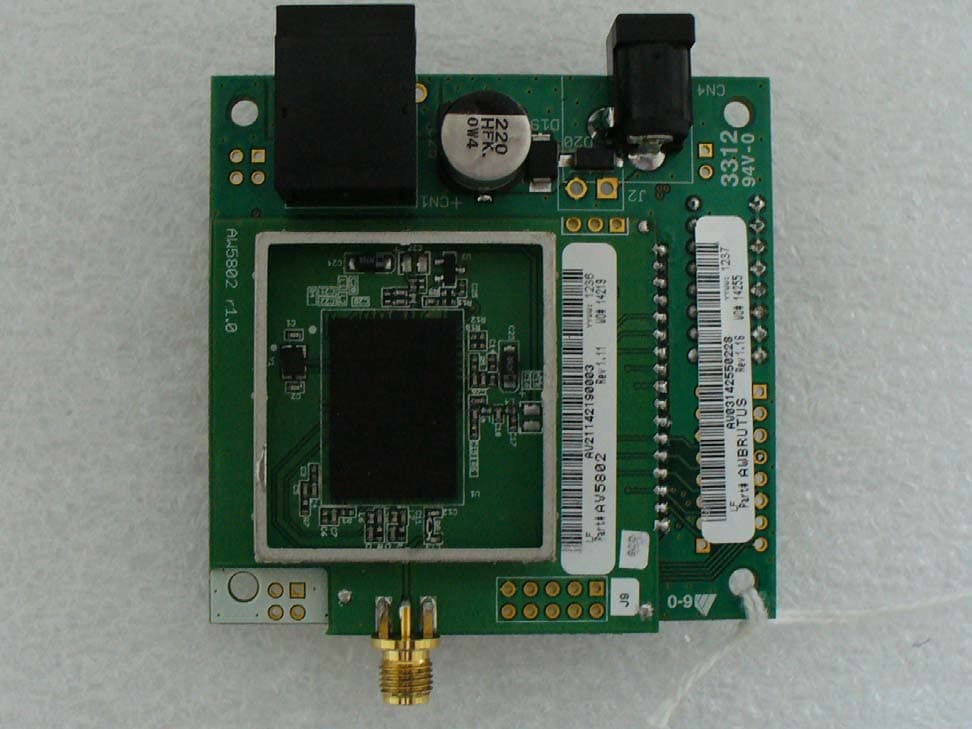
R4N-AW5802MR
Dec 17, 2012AW5802MR
Equipment Class
DTS - Digital Transmission System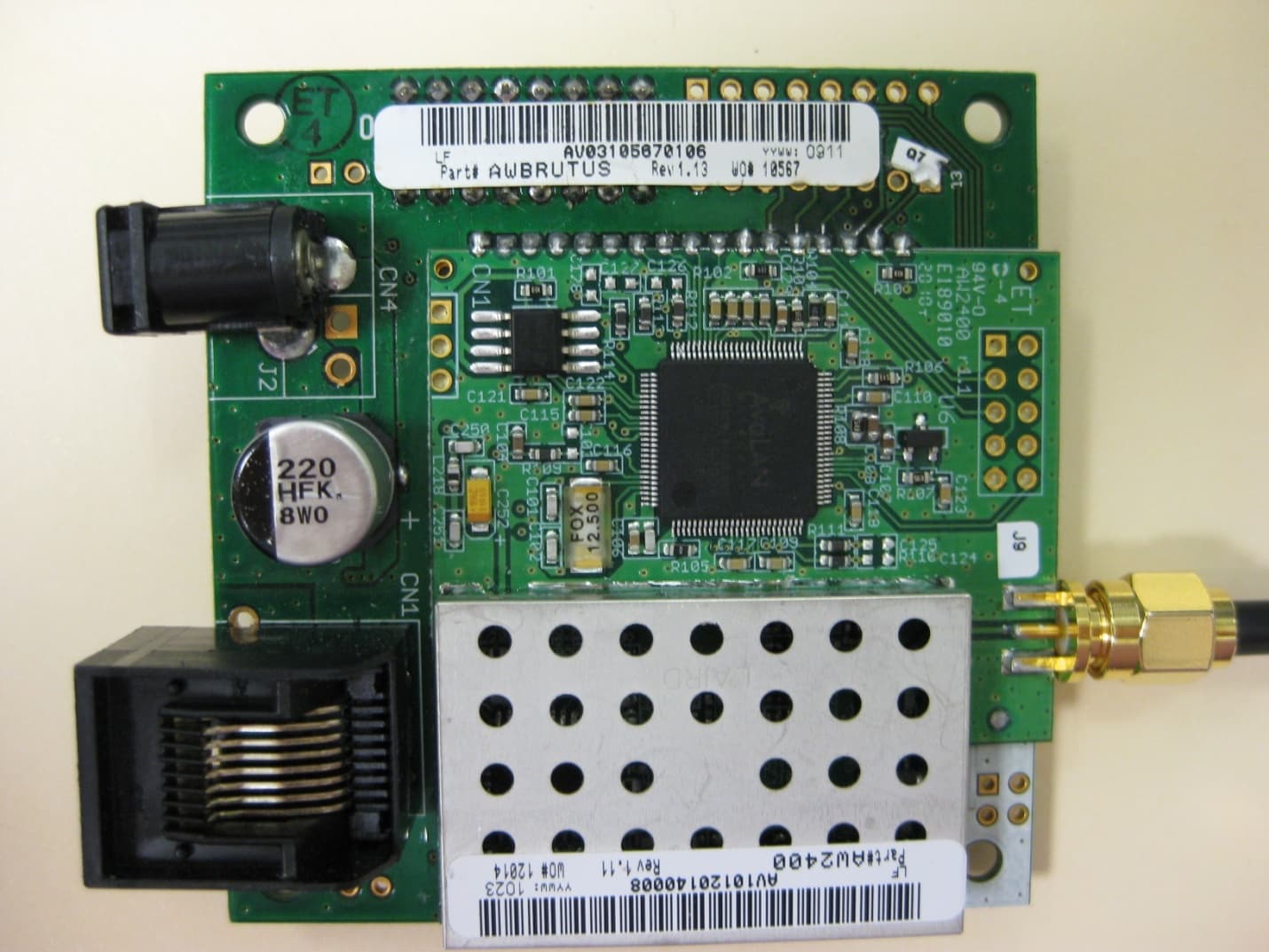
R4N-AW2400MR
Nov 08, 20102.4 GHz Wireless Ethernet Module
Equipment Class
DTS - Digital Transmission System
R4N-AW900M
Sep 08, 2005Ethernet Bridge Transmitter Module
Equipment Class
DTS - Digital Transmission System
R4N-AW900
Oct 28, 2004Digital Spread Spectrum
Equipment Class
DTS - Digital Transmission System