R4N-AW5802MRAW5802MR
Avalan Wireless Systems Incorporated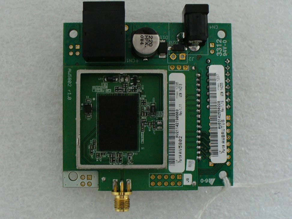
Click to zoom
Application Details
- Equipment Class
- DTS - Digital Transmission System
- Date of Grant
- Dec 17, 2012
- Application Purpose
- Original Equipment
- Date of Application
- Dec 17, 2012
- Equipment Note
- AW5802MR
- Frequency Range
- 5728.12500000 - 5846.90900000
- Country
- United States
Documents & Files
Document Text
Text extracted from the exhibit documents filed with the FCC. Open a document above to read the original.
Users Manual
3998 FAU Blvd. Suite 310 Boca Raton, FL 33431 Tel: 561-961-5585 Fax: 561-961-5587 Certification Exhibit FCC ID: R4N-AW5802MR IC: 5303A-AW5802MR FCC Rule Part: 15.247 IC Radio Standards Specification: RSS-210 ACS Project: 12-2135 Manufacturer: AvaLAN Wireless Systems Inc Model: AW5802MR User Manual User’s ManUal Industrial-grade, long-range wireless Ethernet systems AvaLAN WIRELESS 5.8 GHz Wireless Ethernet Module Evaluation Kit AW5802mTR-EVAL AW5802mTRUser’s Manual PAGE 2 Technical support (650) 384-0000www.avalanwireless.com © 2012 by AvaLAN Wireless Systems Inc. All rights reserved. Revision 12.17.2012 125A Castle Drive Madison, AL 35758 Sales: (866) 533-6216 Technical Support: (650) 384-0000 Customer Service: (650) 641-3011 Fax: (650) 249-3591 Thank you for your purchase of the AW5802mTR-EVAL Wireless Ethernet Module Evaluation Kit. The AW5802mTR Module consists of the AW5802MR Radio Module soldered to a second PC board that provides power and an Ethernet data interface. This Evaluation Kit provides a pair of these Ethernet-interfaced modules along with the necessary accessories to allow your testing and determination of the suitability of these modules for inclusion in your own systems. If you have any questions when configuring your AvaLAN product, the best place to get answers is to visit www.avalanwireless.com. You will also find the latest updates there. If more assistance is needed, send email to [email protected]. To speak to a live technician, please call technical support at the number below during normal business hours. This product is warranted to the original purchaser for normal use for a period of 360 days from the date of purchase. If a defect covered under this warranty occurs, AvaLAN will repair or replace the defective part, at its option, at no cost. This warranty does not cover defects resulting from misuse or modification of the product. Limited Warranty PAGE 3 Technical support (650) 384-0000www.avalanwireless.com User’s ManualAW5802mTR Operational summary The AW5802mTR Radio Module allows the user to create a long-range, wireless Ethernet network with up to 16 subscriber units per access point. Configuring a wireless link with the AW5802mTR requires the establishment of six elements: • Each radio must know whether it is to be an access point (AP) or subscriber unit (SU). • Each radio must have an IP address that is unique among all others on the same network. • The AP must know how many SUs are expecting communication with it. • The AP and any given SU must agree on which radio frequency channel they are using. This can be manually set or allowed to change automatically. • The SU must be assigned a unique subscriber ID to specify which time division slot it will use when communicating with the AP. • The AP and any given SU must share a common 128-bit encryption key. AW5802mTR radios may be configured by two different methods. They may be con- nected to a computer that will run a web browser, setting parameters via their built-in browser interfaces. They may also be programmed via the “easy key” meth- od using the DIP switches and LEDs on the module. The access point (AP) automatically scans for the best of the 59 available radio fre- quency channels, encrypts Ethernet data received from the network, and transmits it wirelessly to the correct subscriber unit (SU). The AP is constantly monitoring the radio link and can automatically change the channel if performance is degraded due to interference. If two AP units are very close to one another, they may interfere if operating on adjacent frequency channels. Place them at least 10 feet apart or manually select non-adjacent channels for their operation. Also, the SU should be placed at least 10 feet from the AP to avoid overloading the radio’s receiver. Any 10/100 BaseT Ethernet client device (ECD) can be connected to an AW5802mTR subscriber unit. Each SU encrypts Ethernet traffic received from the attached ECD and transmits the data wirelessly to its AP. Each SU can be plugged directly into an ECD without adding drivers or loading software. Essentially, once the AP/SU pair is configured and running it behaves like a continuous Ethernet cable. AW5802mTRUser’s Manual PAGE 4 Technical support (650) 384-0000www.avalanwireless.com Evaluation Kit Contents The AW5802mTR-EVAL 5.8 GHz Wireless Ethernet Module Evaluation Kit contains two each of the following items: • AW5802mTR Wireless Ethernet Modules • AW5-5800 Omnidirectional Antennas • AW-P8 Antenna to Radio Connectors • AW-POE Power Over Ethernet Injectors • AW-12VPS 12 Volt Power Supplies Additional quantities of any of these components may be purchased from AvaLAN Wireless or our distributors. To power up a radio module, connect the antenna via the pigtail cable provided. Connect an Ethernet cable to the RJ-45 jack on the module. Power may be sup- plied to the module using the 12 VDC wall hanger power supply either through the Ethernet cable using the POE or directly into the P5 jack on the module. Provide some physical separation between two radio modules — at least five feet. If their antennas are in close proximity, the module radio receivers will be over- loaded, causing degredation in the bit error rate and slower link performance. PAGE 5 Technical support (650) 384-0000www.avalanwireless.com User’s ManualAW5802mTR Physical Dimensions 23 mm 70 mm 66 mm Power: 5-48 VDC Ethernet: 10/100T Power: 9-48 VDC Antenna: Reverse polarity SMA Mounting Holes Mounting Holes 5.8 GHz Channels ChannelCenter FrequencyChannelCenter FrequencyChannelCenter FrequencyChannelCenter Frequency 0Auto Mode 15728.125 MHz165758.845 MHz315789.565 MHz465820.285 MHz 25730.173 MHz175760.893 MHz325791.613 MHz475822.333 MHz 35732.221 MHz185762.941 MHz335793.661 MHz485824.381 MHz 45734.269 MHz195764.989 MHz345795.709 MHz495826.429 MHz 55736.317 MHz205767.037 MHz355797.757 MHz505828.477 MHz 65738.365 MHz215769.085 MHz365799.805 MHz515830.525 MHz 75740.413 MHz225771.133 MHz375801.853 MHz5258…
Text truncated - open the document above for the full version.
Cover Letter(s)
October 29, 2012 Federal Communications Commission Equipment Authorization Branch 7435 Oakland Mills Road Columbia, MD 21046 Dear Sir or Madam, I hereby appoint Sam Wismer at Advanced Compliance Solutions, Inc. to act as our agent in the preparation of an application for equipment authorization of FCC ID: R4N-AW5802MR to the FCC Rules and Regulations. I certify that all exhibits contained within this filing properly describe the device or system for which authorization is sought. I further certify that appropriate arrangements have been made to assure that production units of this equipment bearing the name and FCC IDENTIFIER listed in this application will continue to comply with the Commission's requirements. I further certify by signature below that no party (per 47 CFR 1.2002(b)) to the application is subject to a denial of Federal benefits, including FCC benefits, pursuant to Section 5301 of the Anti-Drug Abuse Act of 1988, 21 U.S.C. 853(a). This appointment also includes the authority to complete FCC Form 731 on our behalf and sign the application as an authorized agent. Sincerely, Michael R Derby CTO/Founder 650 575 7332 [email protected]
Cover Letter(s)
Advanced Compliance Solutions – 5015 B.U. Bowman Drive, Buford, GA 30518 December 7, 2012 Federal Communications Commission Equipment Authorization Branch 7435 Oakland Mills Road Columbia, MD 21046 Gentlemen: AvaLAN Wireless Systems, Inc., respectfully requests confidentiality of certain materials provided with the submission of the AW5802MR under FCC ID: R4N-AW5802MR in accordance with 47 CFR 0.457(d) and 47 CFR 0.459. The confidentiality request applies to the following files. 12-2135 – Block Diagram.pdf 12-2135 – Schematics.pdf 12-2135 – Theory of Operation.pdf The AW5802MR has been developed at considerable effort and expense by AvaLAN Wireless Systems, Inc. These items are considered as Trade Secrets and therefore public access to the proprietary material could possible result in duplication of equipment that could severely damage the company’s business advantage. I appreciate your assistance in this matter. Sincerely, Sam Wismer Vice President, Technology Agent Phone: (770) 831-8048 Fax: (770) 831-8598
Cover Letter(s)
5015 B. U. Bowman Dr. Buford, GA 30518 ACS TCB 5015 B.U. Bowman Drive Buford, GA 30518 Re: FCC ID: R4N-AW5802MR To Whom It May Concern: The following application is submitted on behalf of our client, AvaLAN Wireless Systems, Inc., for evaluation of their model AW5802MR for certification under FCC Part 15.247 for a modular approval. The model AW5802MR, FCC ID: R4N-AW5802MR, is a 5.8 GHz wireless module that can be used for point-to-point and point-to-multipoint operations. The evaluation was performed with the radio module set on a Ethernet browser interface board. The evaluation covers the radio module configured with both a 22 dBi panel antenna and a 5 dBi dipole antenna. The FCC ID: R4N-AW5802MR was tested in full to the aforementioned tests requirements and was found to be in compliance. Sincerely, Sam Wismer Vice President, Technology Advanced Compliance Solutions, Inc.
Cover Letter(s)
125A Castle Drive, Madison, AL 35758 –T (650) 384 0000 – F (650) 249 3591 October 29, 2012 To Whom It May Concern: AvaLAN Wireless would like to apply for Modular FCC approval for FCC ID: R4N-AW5802MR. This letter is our application for such according to FCC public notice DA 00-1407. AW5802MR Modular Transmitter Requirements Modular Transmitter Requirements Manufacturer Clarification A – In order to be considered a transmitter module, the device must be a complete RF transmitter, i.e., it must have its own reference oscillator (e.g., VCO), antenna, etc. The only connectors to the module, if any, may be the power supply and modulation/data inputs. The transmitter is complete with its own reference oscillator, antenna. The only connectors provided are the DC supply, Data, and RF ports. B – Compliance with FCC RF Exposure requirements may, in some instances, limit the output power of a module and/or the final applications in which the approved module may be employed. The radio complies with MPE per 2.1091 for use with mobile or fixed base stations. C – While the applicant for a device into which an authorized module is installed is not required to obtain a new authorization for the module, this does not preclude the possibility that some other form of authorization or testing may be required for the device (e.g., a WLAN into which an authorized module is installed must still be authorized as a PC peripheral, subject to the appropriate equipment authorization). The equipment complies with FCC Part 15, Subpart B, Class B – Unintentional radiators. D – In the case of a modular transceiver, the modular approval policy only applies to the transmitter portion of such devices. Pursuant to Section 15.101(b), the receiver portion will either be subject to Verification, or it will not be subject to any authorization requirements (unless it is a Scanning Receiver, in which case it is also subject to Certification, pursuant to Section 15.101(a)). The receiver operates in 5.8GHz ISM band and complies with FCC Part 15, Subpart B Radio Receivers. 125A Castle Drive, Madison, AL 35758 –T (650) 384 0000 – F (650) 249 3591 Modular Transmitter Requirements Manufacturer Clarification E – The holder of the grant of equipment authorization (Grantee) of the module is responsible for the compliance of the module in its final configuration, provided that the OEM, integrator, and/or end user has complied with all of the instructions provided by the Grantee which indicate installation and/or operating conditions necessary for compliance. End users must conform with the following instructions stated in the users’ manual: - Labeling requirement for equipment using this modular transmitter. - RF Exposure information for compliance with FCC Rules 2.1091 or 2.1093 are specified in the user manual for OEM, integrator, and/or end user. 1. The modular transmitter must have its own RF shielding. This is intended to ensure that the module does not have to rely upon the shielding provided by the device into which it is installed in order for all modular transmitter emissions to comply with Part 15 limits... Such coupling may result in non-compliant operation. The modular transmitter has its own RF shielding. 2. The modular transmitter must have buffered modulation/data inputs (if such inputs are provided) to ensure that the module will comply with Part 15 requirements under conditions of excessive data rates or over-modulation. The modular transmitter has buffered modulation/data inputs. 3. The modular transmitter must have its own power supply regulation. This is intended to ensure that the module will comply with Part 15 requirements regardless of the design of the power supplying circuitry in the device into which the module is installed. The modular transmitter has its own power supply regulation. 4. The modular transmitter must comply with the antenna requirements of Section 15.203 and 15.204c. The antenna must either be permanently attached or employ a “unique” antenna coupler (at all connections between the module and the antenna, including the cable). Any antenna used with the module must be approved with the module; either at the time of initial authorization or through a Class II permissive change. The “professional installation” provision of Section 15.203 may not be applied to modules. The radio complies with Rules 15.203 and 15.204c. The radio may have either a permanently attached wire antenna or a unique antenna coupler (RPSMA or RPTNC) for all other approved antennas. 125A Castle Drive, Madison, AL 35758 –T (650) 384 0000 – F (650) 249 3591 Modular Transmitter Requirements Manufacturer Clarification 5. The modular transmitter must be tested in a stand-alone configuration, i.e., the module must not be inside another device during testing. This is intended to demonstrate that the module is capable of complying with Part 15 emission limits regardless of the device into which it is eventually installed... The modular transmitter was tested in a stand-alone configuration. 6. The modular transmitter must be labeled with its own FCC ID number, and, if the FCC ID is not visible when the module is installed inside another device, then the outside of the device into which the module is installed must also display a label referring to the enclosed module... The modular transmitter is labeled with its own FCC ID number. The label is fixed on the shield. 7. The modular transmitter must comply with any specific rule or operating requirements applicable to the transmitter and the manufacturer must provide adequate instructions along with the module to explain any such requirements. The user manual for the AW5802MR contains adequate instructions relating to the usage, approved antennas, and power supply requirements of the modular transmitter. 8. The modular transmitter must comply with any applicable RF exposure requirements. The modular transmitter was tested to applicable RF exposure requirements. Sincerely, Michael R Derby C…
Text truncated - open the document above for the full version.
ID Label/Location Info
3998 FAU Blvd. Suite 310 Boca Raton, FL 33431 Tel: 561-961-5585 Fax: 561-961-5587 Certification Exhibit FCC ID: R4N-AW5802MR IC: 5303A-AW5802MR FCC Rule Part: 15.247 IC Radio Standards Specification: RSS-210 ACS Project: 12-2135 Manufacturer: AvaLAN Wireless Systems Inc Model: AW5802MR Label Information Model: AW5802MR FCC ID: R4N-AW5802MR IC: 5303A-AW5802MR Figure 1: Sample Label and Location ACS Project: 12-2135 Advanced Compliance Solutions Page 2
Internal Photos
3998 FAU Blvd. Suite 310 Boca Raton, FL 33431 Tel: 561-961-5585 Fax: 561-961-5587 Certification Exhibit FCC ID: R4N-AW5802MR IC: 5303A-AW5802MR FCC Rule Part: 15.247 IC Radio Standards Specification: RSS-210 ACS Project: 12-2135 Manufacturer: AvaLAN Wireless Systems Inc Model: AW5802MR Internal Photos Model: AW5802MR FCC ID: R4N-AW5802MR IC: 5303A-AW5802MR Figure 1: Top View (without shielding) – mounted on Ethernet board ACS Project: 12-2135 Advanced Compliance Solutions Page 2 Model: AW5802MR FCC ID: R4N-AW5802MR IC: 5303A-AW5802MR Figure 2 Top View (without shielding) – module standalone ACS Project: 12-2135 Advanced Compliance Solutions Page 3 Model: AW5802MR FCC ID: R4N-AW5802MR IC: 5303A-AW5802MR Figure 3: Bottom View – module standalone ACS Project: 12-2135 Advanced Compliance Solutions Page 4
RF Exposure Info
3998 FAU Blvd. Suite 310 Boca Raton, FL 33431 Tel: 561-961-5585 Fax: 561-961-5587 Certification Exhibit FCC ID: R4N-AW5802MR IC: 5303A-AW5802MR FCC Rule Part: 15.247 IC Radio Standards Specification: RSS-210 ACS Project Number: 12-2135 Manufacturer: AvaLAN Wireless Systems Model: AW5802MR RF Exposure Model: AW5802MR FCC ID: R4N-AW5802MR IC: 5303A-AW5802MR General Information: Applicant: AvaLAN Wireless Systems ACS Project: 12-2135 Device Category: Mobile Environment: General Population/Uncontrolled Exposure Technical Information: Antenna Type 1: Panel Antenna Antenna Gain 1: 22 dBi Antenna Type 2: Dipole Antenna Antenna Gain 2: 5 dBi Maximum Transmitter Conducted Power: 13.91 dBm, 24.6 mW Maximum System EIRP: 35.91 dBm, 3899.42 mW Exposure Conditions: Greater than 20 centimeters * Note: The maximum EIRP and Power Density are calculated using the highest antenna gain. MPE Calculation The Power Density (mW/cm 2 ) is calculated as follows: S = 2 4R PG π Where: S = power density (in appropriate units, e.g. mW/cm2) P = power input to the antenna (in appropriate units, e.g., mW) G = power gain of the antenna in the direction of interest relative to an isotropic radiator R = distance to the center of radiation of the antenna (appropriate units, e.g., cm) MPE Calculator for Mobile Equipment Limits for General Population/Uncontrolled Exposure* 5787.51713.911.0024.6022158.489 200.776 Power Densit y (mW/cm^2) Distance (cm) Transmit Frequency (MHz) Radio Power (dBm) Power Density Limit (mW/Cm2) Radio Power (mW) Antenna Gain (dBi) Antenna Gain (mW eq.) Installation Guidelines The installation manual should contain text similar to the following advising how to install the equipment to maintain compliance with the FCC RF exposure requirements: RF Exposure In accordance with FCC requirements of human exposure to radio frequency fields, the radiating element shall be installed such that a minimum separation distance of 20 centimeters will be maintained. Conclusion This device complies with the MPE requirements by providing adequate separation between the device, any radiating structure and the general population. ACS Project: 12-2135 Advanced Compliance Solutions Page 2
Test Report
3998 FAU Blvd. Suite 310 Boca Raton, FL 33431 Tel: 561-961-5585 Fax: 561-961-5587 Certification Test Report FCC ID: R4N-AW5802MR IC: 5303A-AW5802MR FCC Rule Part: 15.247 IC Radio Standards Specification: RSS-210 ACS Report Number: 12-2135.W06.1A Manufacturer: AvaLAN Wireless Systems Model: AW5802MR Test Begin Date: October 17, 2012 Test End Date: December 5, 2012 Report Issue Date: December 7, 2012 FOR THE SCOPE OF ACCREDITATION UNDER CERTIFICATE NUMBER AT-1533 This report must not be used by the client to claim product certification, approval, or endorsement by ACLASS, ANSI, or any agency of the Federal Government. Project Manager: Reviewed by: Steve O'Steen Kirby Munroe EMC Technician Director, Wireless Certifications Advanced Compliance Solutions, Inc. Advanced Compliance Solutions, Inc. This test report shall not be reproduced except in full. This report may be reproduced in part with prior written consent of ACS, Inc. The results contained in this report are representative of the sample(s) submitted for evaluation. This report contains 45 pages TABLE OF CONTENTS 1 GENERAL ......................................................................................................3 1.1 Purpose .............................................................................................................................................. 3 1.2 Product Description.......................................................................................................................... 3 1.3 Test Methodology and Considerations ........................................................................................... 3 2 TEST FACILITIES ..........................................................................................4 2.1 Location ............................................................................................................................................. 4 2.2 Laboratory Accreditations/Recognitions/Certifications ............................................................... 4 2.3 Radiated & Conducted Emissions Test Site Description .............................................................. 5 3 APPLICABLE STANDARD REFERENCES...................................................7 4 LIST OF TEST EQUIPMENT..........................................................................8 5 SUPPORT EQUIPMENT ................................................................................9 6 EQUIPMENT UNDER TEST SETUP BLOCK DIAGRAM ............................10 7 SUMMARY OF TESTS .................................................................................11 7.1 Antenna Requirement – FCC: Section 15.203 ............................................................................. 11 7.2 6 dB Bandwidth - FCC: Section 15.247(a)(2) 99% Bandwidth IC: RSS-210 A8.2(a)............... 11 7.3 Peak Output Power - FCC Section 15.247(b)(3) IC: RSS-210 A8.4(4)....................................... 18 7.4 Band-Edge Compliance and Spurious Emissions-FCC 15.247(d) IC:RSS-210 A8.5................ 22 7.5 Power Spectral Density - FCC Section 15.247(e) IC: RSS-210 A8.2(b) ..................................... 38 7.6 Power Line Conducted Emissions – FCC: Section 15.207 IC: RSS-Gen 7.2.4 .......................... 42 8 CONCLUSION..............................................................................................45 Model: AW5802MR FCC ID: R4N-AW5802MR IC: 5303A-AW5802MR ACS Report: 12-2135.W06.1A Advanced Compliance Solutions Page 3 of 45 1 GENERAL 1.1 Purpose The purpose of this report is to demonstrate compliance with Part 15 Subpart C of the FCC’s Code of Federal Regulations and Industry Canada’s Radio Standards Specification RSS-210 for a modular approval. 1.2 Product Description This AW5802MR is a wireless module used to transmit digital data packets in the 5.8GHz ISM band. The radio module is controlled by an Ethernet based browser interface board. Technical Information: Band of Operation: 5728.125 MHz - 5846.909 MHz Number of Channels: 59 Modulation Format: FSK Antenna Type/Gain: Panel Antenna, 22 dBi Dipole Antenna, 5 dBi Data Rates: 1.536 Mbps, 2.048 Mbps Operating Voltage: 4.5 VDC - 48 VDC Manufacturer Information: AvaLAN Wireless Systems 125A Castle Dr Madison AL 35758 Test Sample Serial Number(s): AV21142190003 Test Sample Condition: The unit was in good operating condition with no physical damages. 1.3 Test Methodology and Considerations The AW5802MR was evaluated with the Ethernet based browser interface board powered via a 12 VDC wall adapter. The unit was controlled via a remote laptop computer. For the radiated emissions evaluation, the unit was evaluated with both a panel and a dipole antenna up to 40 GHz. Measurements were performed for the unit set three orthogonal orientations and at the two available data rates. 1.5 Mbps and 2 Mbps. Where applicable, the results are reported for the configurations leading to the highest emissions. The RF conducted measurements were performed at both data rates up to 40 GHz. The evaluation for the unintentional emissions is documented separately in a Verification Report. Model: AW5802MR FCC ID: R4N-AW5802MR IC: 5303A-AW5802MR ACS Report: 12-2135.W06.1A Advanced Compliance Solutions Page 4 of 45 2 TEST FACILITIES 2.1 Location The radiated and conducted emissions test sites are located at the following address: Advanced Compliance Solutions, Inc. 3998 FAU Blvd, Suite 310 Boca Raton, Florida 33431 Phone: (561) 961-5585 Fax: (561) 961-5587 www.acstestlab.com FCC Test Firm Registration #: 587595 Industry Canada Lab Code: 4175C 2.2 Laboratory Accreditations/Recognitions/Certifications ACS is accredited to ISO/IEC 17025 by ANSI-ASQ National Accreditation Board under their ACLASS program and has been issued certificate number AT-1533 in recognition of this accreditation. Unless otherwise specified, all test methods described within this report are covered under the ISO/IEC 17025 scope of accreditation. Model: AW5802MR FCC ID: R4N-AW5802MR IC: 5…
Text truncated - open the document above for the full version.
Test Setup Photos
3998 FAU Blvd. Suite 310 Boca Raton, FL 33431 Tel: 561-961-5585 Fax: 561-961-5587 Certification Exhibit FCC ID: R4N-AW5802MR IC: 5303A-AW5802MR FCC Rule Part: 15.247 IC Radio Standards Specification: RSS-210 ACS Project: 12-2135 Manufacturer: AvaLAN Wireless Systems Inc Model: AW5802MR Test Setup Photos Model: AW5802MR FCC ID: R4N-AW5802MR IC: 5303A-AW5802MR Figure 1: Radiated Emissions – EUT with Dipole Antenna (Front View) ACS Project: 12-2135 Advanced Compliance Solutions Page 2 Model: AW5802MR FCC ID: R4N-AW5802MR IC: 5303A-AW5802MR Figure 2: Radiated Emissions – EUT with Dipole Antenna (Back View) ACS Project: 12-2135 Advanced Compliance Solutions Page 3 Model: AW5802MR FCC ID: R4N-AW5802MR IC: 5303A-AW5802MR Figure 3: Radiated Emissions – EUT with Panel Antenna (Front View) ACS Project: 12-2135 Advanced Compliance Solutions Page 4 Model: AW5802MR FCC ID: R4N-AW5802MR IC: 5303A-AW5802MR Figure 4: Radiated Emissions – EUT with Panel Antenna (Back View) ACS Project: 12-2135 Advanced Compliance Solutions Page 5 Model: AW5802MR FCC ID: R4N-AW5802MR IC: 5303A-AW5802MR Figure 5: RF Conducted Emissions ACS Project: 12-2135 Advanced Compliance Solutions Page 6 Model: AW5802MR FCC ID: R4N-AW5802MR IC: 5303A-AW5802MR Figure 6: Power Line Conducted Emissions – EUT with Dipole Antenna (Front View) ACS Project: 12-2135 Advanced Compliance Solutions Page 7 Model: AW5802MR FCC ID: R4N-AW5802MR IC: 5303A-AW5802MR Figure 7: Power Line Conducted Emissions – EUT with Dipole Antenna (Side View) ACS Project: 12-2135 Advanced Compliance Solutions Page 8 Model: AW5802MR FCC ID: R4N-AW5802MR IC: 5303A-AW5802MR Figure 8: Power Line Conducted Emissions – EUT with Panel Antenna (Front View) ACS Project: 12-2135 Advanced Compliance Solutions Page 9 Model: AW5802MR FCC ID: R4N-AW5802MR IC: 5303A-AW5802MR Figure 9: Power Line Conducted Emissions – EUT with Panel Antenna (Side View) ACS Project: 12-2135 Advanced Compliance Solutions Page 10
Contact Information
Applicant
Michael R Derby(CTO)
Test Firm
Advanced Compliance Solutions, Inc.Sam Wismer
[email protected]561-961-5585
Technical Specifications
| # | Rule Parts | Frequency Range | Power Output |
|---|---|---|---|
| 1 | 15C | 5.73 GHz - 5.85 GHz | 24.60 mW |
Other Applications from Avalan Wireless Systems Incorporated
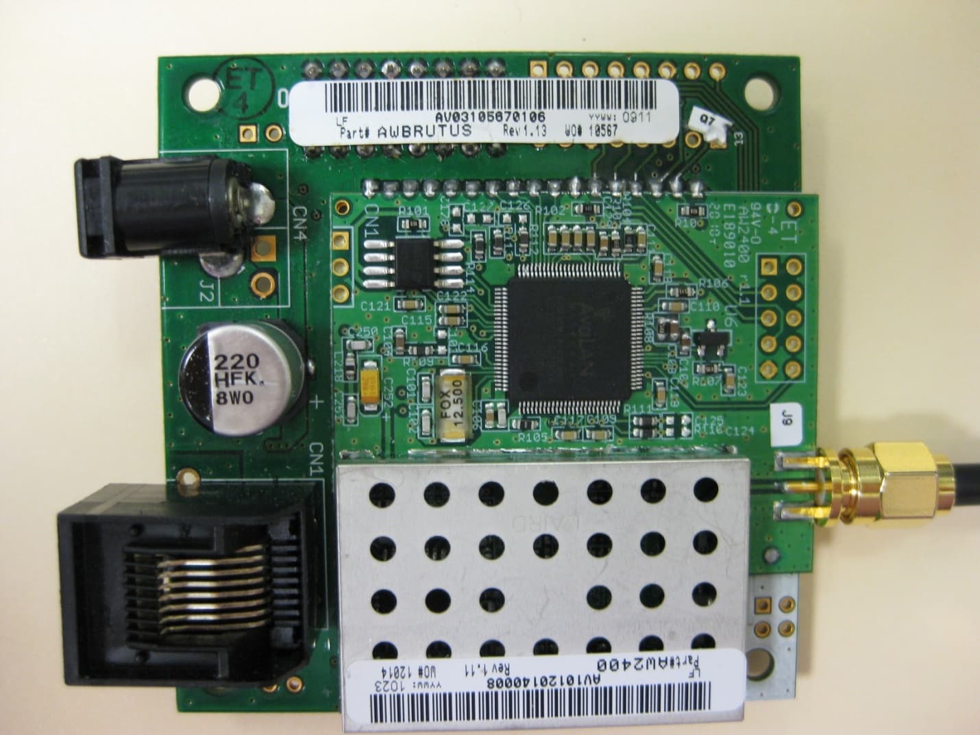
R4N-AW2400MR
Nov 08, 20102.4 GHz Wireless Ethernet Module
Equipment Class
DTS - Digital Transmission System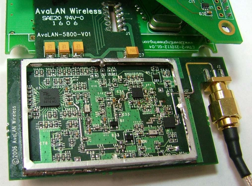
R4N-AW5800M
Jul 19, 20065.8GHz Wireless Ethernet Bridge Module
Equipment Class
DTS - Digital Transmission System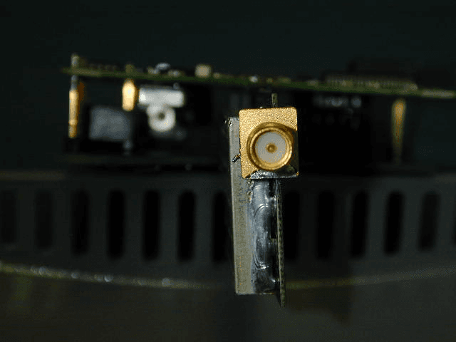
R4N-AW900M
Sep 08, 2005Ethernet Bridge Transmitter Module
Equipment Class
DTS - Digital Transmission System
R4N-AW900
Oct 28, 2004Digital Spread Spectrum
Equipment Class
DTS - Digital Transmission System