R4N-AW900Digital Spread Spectrum
Avalan Wireless Systems Incorporated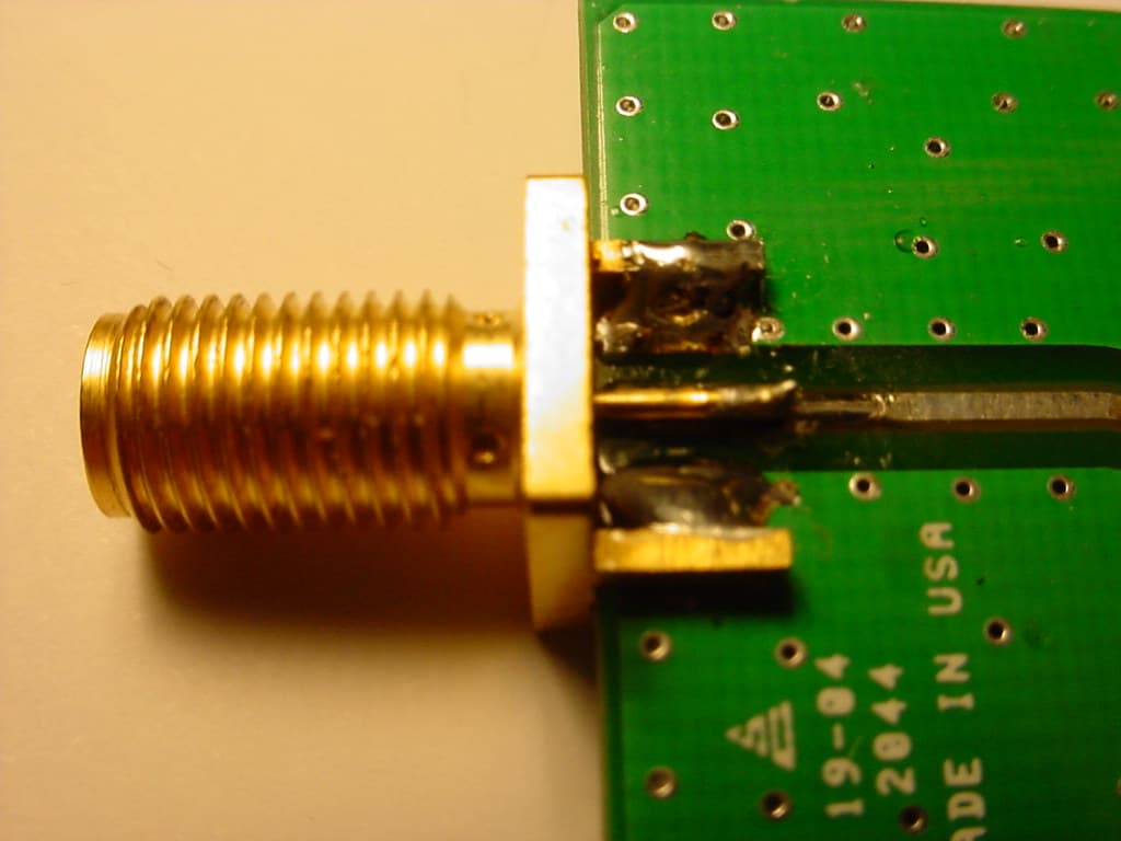
Click to zoom
Application Details
- Equipment Class
- DTS - Digital Transmission System
- Date of Grant
- Oct 28, 2004
- Application Purpose
- Original Equipment
- Date of Application
- Oct 28, 2004
- Equipment Note
- Digital Spread Spectrum
- Frequency Range
- 902.00000000 - 928.00000000
- Country
- United States
Documents & Files
Document Text
Text extracted from the exhibit documents filed with the FCC. Open a document above to read the original.
Users Manual
Long Range Wireless DSL-Ethernet Extender Enabling high speed internet everywhere! Features: • Long range, Non-Line-of-Sight Wireless Ethernet Bridging at DSL speed • Does not interfere with Wi-Fi networks - enabling wireless backhaul to the AP • Highest Quality of Service (QoS) available – Synchronous point to point protocol enables extremely low data latency (<1ms) and minimized jitter suitable for VoIP and video applications • 128bit encrypted payload protection provides secure data delivery. • Simple plug and play set up auto-configured as matched pairs • Operates in the 902-928MHz band and does not require an FCC license to operate or install • Compatible with Power over Ethernet injector/splitters • VLAN extensions supported Applications: • Difficult to wire Wi-Fi Access Points • Difficult to wire Pan/Tilt/Zoom Ethernet Video Cameras • Mobile or difficult to wire Kiosk installations • Long distance indoor wireless Ethernet links • Non-line-of-sight outdoor wireless Ethernet links • Long range extension of VoIP telephone installations Range: Indoor AW900 Antenna: +2.5dBi omni Indoor Range: (typical) - Over 2500ft with 4 walls* - 5x the range of 802.11@2Mbps Technical Specifications: (typical) 1.536 Mb/s raw data rate enables usable throughput that is 15% faster than 768Kb/s DSL 21 dBm output power -101dBm receive sensitivity at 10e -4 BER 16 Status LEDs - Power, RF Link, Ethernet Link, Traffic, RF RX, RF TX, 4/Channel and 6/Link Quality 12 Non-overlapping channels - automatically selected and adaptively optimized (or manually selected) Block error detection/correction improves throughput and ensures a robust link Direct sequence spread spectrum with adaptive coding rates Temperature range -30°C to 60°C High performance SAW filter protects against adjacent-band Cellular and Pager interference AvaLAN Wireless Systems Inc. www.avalanwireless.com 2400 West El Camino Real Suite # 317 Mountain View, CA 94040 Tel (650) 444-5117 [email protected] [email protected] Contents: 2 Power Adapters 2 Ethernet Cables 2 Antennae 2 AW900 Radio Units Setup: Any Ethernet device can be connected – PC, Ethernet video camera, hub, router, etc. The AW900 functions in place of an Ethernet cable and provides a transparent wireless point to point Ethernet cable replacement. Cross-over cables are not necessary as the AW900 automatically senses which type of device is present (client or hub). AW900 Ethernet RJ45 Power 110VAC AW900 Ethernet RJ45 Power 110VAC Troubleshooting: Under normal operation the Green LED will be flickering whenever there is Ethernet traffic being transported. The light should be on steady when the link is up but no traffic is present. No Light: Check the power connections. Blinking light: (0.5 seconds on then 0.5 seconds off) The radio is looking for its matched partner. If both units are powered up and the lights continue to blink they may be too far away to create the connection. Try other locations that may have a less obstructed path or try to reorient the antennas. Solid light but still not working: Check your network. Flickering light but still not working: Unplug both AW900 units for 5 seconds and plug back in. If this does not fix things then unplug and replug your attached network devices. The AW900 keeps track of Ethernet MAC address to avoid transporting unnecessary traffic. This will force a complete refresh the attached-MAC address tables in the AW900 and should resolve any issues. Still not working? If practical, use an Ethernet cable to see if the network is working over a wired connection. If a wire does not work then the problem is with the network. Email: [email protected] Product limited warranty: This product is warranted to the original purchaser for normal use for a period of 90 days from the date of purchase. If a defect covered under this warranty occurs Avalan will repair or replace the defective part, at its option, at no cost. This warranty does not cover defects resulting from misuse or modification of the product. Compliance Statement ( Part 15.19 ) This device complies with Part 15 of the FCC Rules. Operation is subject to the following two conditions: 1. This device may not cause harmful interference, and 2. This device must accept any interference received, including interference that may cause undesired operation. Warning ( Part 15.21 ) Changes or modifications not expressly approved by the party responsible for compliance could void the user’s authority to operate the equipment. RF Exposure ( OET Bulletin 65 ) To comply with FCC RF exposure requirements for mobile transmitting devices, this transmitter should only be used or installed at locations where there is at least 20cm separation distance between the antenna and all persons. Information to the User - Part 15.105 (b) Note: This equipment has been tested and found to comply with the limits for a Class B digital device, pursuant to part 15 of the FCC Rules. These limits are designed to provide reasonable protection against harmful interference in a residential installation. This equipment generates, uses and can radiate radio frequency energy and, if not installed and used in accordance with the instructions, may cause harmful interference to radio communications. However, there is no guarantee that interference will not occur in a particular installation. If this equipment does cause harmful interference to radio or television reception, which can be determined by turning the equipment off and on, the user is encouraged to try to correct the interference by one or more of the following measures: --Reorient or relocate the receiving antenna. --Increase the separation between the equipment and receiver. --Connect the equipment into an outlet on a circuit different from that to which the receiver is connected. --Consult the dealer or an experienced radio/TV technician for help.
External Photos
Avalan Wireless Systems, Inc. Wireless DSL-Ethernet Extender FCC ID#: R4N-AW900 Photo One – External Wireless DSL-Ethernet Extender with Power Pack. Avalan Wireless Systems, Inc. Wireless DSL-Ethernet Extender FCC ID#: R4N-AW900 Photo Two – External Power Connection and Ethernet Port Avalan Wireless Systems, Inc. Wireless DSL-Ethernet Extender FCC ID#: R4N-AW900 Photo Three – External Antenna Connection Avalan Wireless Systems, Inc. Wireless DSL-Ethernet Extender FCC ID#: R4N-AW900 Photo Four – External Close Up of Antenna Connection Avalan Wireless Systems, Inc. Wireless DSL-Ethernet Extender FCC ID#: R4N-AW900 Photo Five – External Bottom of Product with FCC ID Label Avalan Wireless Systems, Inc. Wireless DSL-Ethernet Extender FCC ID#: R4N-AW900 Photo Six – External Close Up of FCC ID Label
ID Label/Location Info
AvaLAN Wireless Systems Inc. Long Range Wireless DSL-Ethernet Extender Tel (650) 444-5117 www.avalanwireless.com This device complies with Part 15 of the FCC Rules. Operation is subject to the following two conditions: 1) this device may not cause harmful interference, and 2) this device must accept any interference received, including interference that may cause undesired operation. FCC ID : R4N-AW900 S/N : 000102 MODEL : AW900 Made in USA Technical Data Sheet TDS No. B-423 Effective Date: 06/03/2004 BRADYBONDZ(TM) B-423 THERMAL TRANSFER PRINTABLE GLOSSY WHITE POLYESTER LABEL STOCK Details: BRADY WORLDWIDE, INC. P.O. Box 2131 Milwaukee, WI 53201-2131 Tel. 414/358-6600 Fax 800/292-2289 Description : GENERAL Print Technology: Thermal transfer Materials Type: White polyester Finish: Glossy white Adhesive: Permanent acrylic APPLICATIONS Electronic PCB and component identification, bar code label and rating plates. RECOMMENDED RIBBONS Brady series R6000 Brady series R4400 (colors - red, blue, green, white) Brady series R4900 and R6200 (alternates) AGENCY APPROVALS UL: B-423 is a UL Recognized Component to UL969 Labeling and Marking Standard when printed with Brady Series R6000 ribbon. See UL file MH17154 for specific details. UL information can be accessed on line at UL.com. Search in Certifications area. The Brady Series R4900 ribbon is also UL approved. CSA: B-423 is CSA Accepted to C22.2 No.0.15-95 Adhesive Labels Standard when printed with Brady Series R6000 ribbon. See CSA file 041833 for specific details. CSA information can be accessed online at directories.csa-international.org. DIN VDE 0472 Part 815: Brady B-423 meets requirements of a halogen- free material per DIN VDE 0472 part 815. (Statement based on review of product construction and confirmation halogen content test run at an independent test laboratory.) PHYSICAL PROPERTIES TEST METHODS AVERAGE RESULTS ThicknessASTM D 1000 -Substrate -Adhesive 0.002 inch (0.0508 mm) 0.001 inch (0.0254 mm) 0.003 inch (0.0762 mm) Page 1 of 4TDS - BRADYBONDZ(TM) B-423 THERMAL TRANSFER PRINTABLE GLOSS... 8/16/2004http://www.bradyid.com/tds/tdsv1r0.nsf/16a6991f10d79a4d86256cee004a3a6d/2... B-423 is not recommended for low surface energy surfaces such as polyethylene and polypropylene. Performance properties tested on B-423 printed with Series R6000 and R6200 ribbons using the Bradyprinter™ THT Model 300X-Plus thermal transfer printer. Printed samples were laminated to aluminum and allowed to dwell 24 hours before exposure to the indicated environments. Unless noted, results are the same for both ribbons. -Total Adhesion to: -Stainless Steel - Painted Enamel - Textured ABS ASTM D 1000 20 minute dwell 24 hour dwell 20 minutes dwell 24 hour dwell 20 minutes dwell 24 hour dwell 51 oz/inch (56 N/100 mm) 78 oz/inch (85 N/100 mm) 54 oz/inch (59 N/100 mm) 67 oz/inch (73 N/100 mm) 10 oz/inch (11 N/100 mm) 15 oz/inch (17 N/100mm) TackASTM D 2979 Polyken™ Probe Tack 1 second dwell 21 oz (600 g) Dielectric StrengthASTM D 10008600 Volts PERFORMANCE PROPERTIES TEST METHOD TYPICAL RESULTS High Service Temperature30 days at various temperatures No visible effect to label at 110°C. Slight discoloration at 120° C; moderate discoloration at 145°C but label is still functional. Low Service Temperature30 days at -70°CNo visible effect Short Term High Service Temperature 5 minutes at various temperatures No visible effect to label at 180°C. Slight discoloration and label shrinkage at 200°C; label is functional. Label becomes nonfunctional at 210°C due to label shrinkage. Humidity Resistance30 days at 100°F (37°C) and 95% relative humidity. No visible effect UV Light Resistance30 days in UV Sunlighter™ 100 Slight discoloration WeatherabilityASTM G26 30 days in Xenon Arc Weatherometer No visible effect Salt Fog ResistanceASTM B 117 30 days in 5% salt fog solution chamber No visible effect Page 2 of 4TDS - BRADYBONDZ(TM) B-423 THERMAL TRANSFER PRINTABLE GLOSS... 8/16/2004http://www.bradyid.com/tds/tdsv1r0.nsf/16a6991f10d79a4d86256cee004a3a6d/2... Samples were printed with Series R6000 and R6200 ribbons using a Bradyprinter™ 300X- Plus thermal transfer printer. Samples were laminated to aluminum panels and allowed to dwell 24 hours prior to testing. Testing was conducted at room temperature and consisted of 30 minute immersions in the specified test fluid. After immersion, the samples were removed from the test fluid and the printed image rubbed 10 times with a cotton swab saturated with the test fluid. The rating scale below shows the effect to the quality of the print for each sample. Rating Scale: PERFORMANCE PROPERTY CHEMICAL RESISTANCE CHEMICAL REAGENT SUBJECTIVE OBSERVATION OF VISUAL CHANGE EFFECT TO LABEL STOCK EFFECTS TO PRINTED IMAGE R6000 R6200 WITHOUT RUB WITH RUB WITHOUT RUB WITH RUB AcetoneSlight adhesive ooze 1 5 1 5 TolueneSlight adhesive ooze 1 5 1 5 Isopropyl Alcohol No visible effect 1 1 1 1 Mineral SpiritsNo visible effect 1 1 1 1 GasolineSlight adhesive ooze 1 1 1 1 JP-8 Jet FuelSlight adhesive ooze 1 1 1 1 Brake FluidNo visible effect 1 1-2 1 5 Skydrol ® 500B-4 Slight adhesive ooze 1 5 2 5 SAE 20 WT Oil at 70°C No visible effect 1 1 1 1 MIL 5606 OilNo visible effect 1 1 1 1 Formula 409 ® Cleaner No visible effect 1 1 1 1 Northwoods ™ Buzz Saw Citrus Degreaser No visible effect 1 1 1 1 Deionized Water No visible effect 1 1 1 1 Page 3 of 4TDS - BRADYBONDZ(TM) B-423 THERMAL TRANSFER PRINTABLE GLOSS... 8/16/2004http://www.bradyid.com/tds/tdsv1r0.nsf/16a6991f10d79a4d86256cee004a3a6d/2... 1= no visible effect 2= slight smear or print removal, detectable but minimal smear 3= moderate smear or print removal (print still legible) 4= severe smear or print removal (print illegible or just barely legible) 5= complete print and/or topcoat removal NP= print removed prior to rub Product testing, customer feedback, and history of similar products, support a customer performance expectation of at least two years from the date of receipt for this product as long as this…
Text truncated - open the document above for the full version.
Internal Photos
AvaLAN Exterior Photos
Internal Photos
Avalan Wireless Systems, Inc. Wíreless DSL-Ethernet Extender FCC ID#: R4N-AW900 Photo One – Internal Open for Inspection Avalan Wireless Systems, Inc. Wíreless DSL-Ethernet Extender FCC ID#: R4N-AW900 Photo Two – Internal Close Up of Antenna Connection Avalan Wireless Systems, Inc. Wíreless DSL-Ethernet Extender FCC ID#: R4N-AW900 Photo Three – Internal RF Section shown Removed from Product Avalan Wireless Systems, Inc. Wíreless DSL-Ethernet Extender FCC ID#: R4N-AW900 Photo Four – Internal RF PCB with Shield Removed Avalan Wireless Systems, Inc. Wireless DSL-Ethernet Extender FCC ID#: R4N-AW900 Photo Five – Internal RF PCB Flip Side
Test Report
L.S. Compliance, Inc. W66 N220 Commerce Court Cedarburg, WI 53012 262-375-4400 Fax: 262-375-4248 COMPLIANCE TESTING OF : AW900 Wireless Ethernet Link Prepared For: AvaLAN Wireless Systems, Inc. Attention: Mr. Mike Derby 2400 El Camino Real Suite 317 Mountain View, CA 94040 Test Report Number: 304224 TX TCB Rev. 1 Test Dates: May 5 th -26 th , 2004 All results of this report relate only to the items that were tested. This report is not to be reproduced, except in full, without written approval of L. S. Compliance, Inc. L.S. Compliance, Inc. Page 2 of 37 Test Report Number: 304224 TX TCB Rev. 1 Prepared For: AvaLAN Wireless Systems, Inc. Table of Contents Section Description Page Index 2 1 L. S. Compliance in Review 3 2 A2LA Certificate of Accreditation 4 3 A2LA Scope of Accreditation 5 4 Validation Letter-U.S. Competent Body for EMC Directive 89/336/EEC 6 5 Signature Page 7 6 Product and General Information 8 7 Introduction 8 8 Product Description 8 9 Test Requirements 9 10 Summary of Test Report 9 11 Radiated Emissions Test 10-18 12 Band-Edge Measurements 19 13 Conducted Emissions Test, AC Power Line 20-24 14 Conducted Emissions Test, Power Output 15.247 (b) 25-26 15 Conducted Emissions Test, Spurious Emissions 15.247 (d) 27-30 16 Conducted Emissions Test, Occupied Bandwidth 31-32 17 Conducted Emissions Test, Spectral Density 33-34 18 MPE Calculations 35 Appendix A Test Equipment List 36 B Antenna Specifications 37 L.S. Compliance, Inc. Page 3 of 37 Test Report Number: 304224 TX TCB Rev. 1 Prepared For: AvaLAN Wireless Systems, Inc. 1. L. S. Compliance In Review L.S. Compliance – Accreditations and Listing’s As an EMC Testing Laboratory, our Accreditation and Assessments are recognized through the following: A2LA – American Association for Laboratory Accreditation Accreditation based on ISO/IEC 17025 : 1999 with Electrical (EMC) Scope of Accreditation A2LA Certificate Number: 1255.01 Federal Communications Commission (FCC) – USA Listing of 3 Meter Semi-Anechoic Chamber based on Title 47 CFR – Part 2.948 FCC Registration Number: 90756 Listing of 3 and 10 meter OATS based on Title 47CFR – Part 2.948 FCC Registration Number: 90757 Industry Canada On file, 3 Meter Semi-Anechoic Chamber based on RSS-212 – Issue 1 File Number: IC 3088-A On file, 3 and 10 Meter OATS based on RSS-212 – Issue 1 File Number: IC 3088 U. S. Conformity Assessment Body (CAB) Validation Validated by the European Commission as a U. S. Competent Body operating under the U. S. /EU, Mutual Recognition Agreement (MRA) operating under the European Union Electromagnetic Compatibility –Council Directive 89/336/EEC, Article 10.2. Date of Validation: January 16, 2001 Validated by the European Commission as a U.S. Notified Body operating under the U.S./EU, Mutual Recognition Agreement (MRA) operating under the European Union Telecommunication Equipment – Council Directive 99/5/EC, Annex V. Date of Validation: November 20, 2002 Notified Body Identification Number: 1243 L.S. Compliance, Inc. Page 4 of 37 Test Report Number: 304224 TX TCB Rev. 1 Prepared For: AvaLAN Wireless Systems, Inc. 2. A2LA Certificate of Accreditation L.S. Compliance, Inc. Page 5 of 37 Test Report Number: 304224 TX TCB Rev. 1 Prepared For: AvaLAN Wireless Systems, Inc. 3. A2LA Scope of Accreditation L.S. Compliance, Inc. Page 6 of 37 Test Report Number: 304224 TX TCB Rev. 1 Prepared For: AvaLAN Wireless Systems, Inc. 4. Validation Letter – U.S. Competent Body for EMC Directive 89/336/EEC L.S. Compliance, Inc. Page 7 of 37 Test Report Number: 304224 TX TCB Rev. 1 Prepared For: AvaLAN Wireless Systems, Inc. 5. Signature Page Prepared By: October 25, 2004 Teresa A. White, Document Coordinator Date Tested By: October 25, 2004 Abtin Spantman, EMC Engineer Date Approved By: October 25, 2004 Kenneth L. Boston, EMC Lab Manager Date PE #31926 Licensed Professional Engineer Registered in the State of Wisconsin, United States L.S. Compliance, Inc. Page 8 of 37 Test Report Number: 304224 TX TCB Rev. 1 Prepared For: AvaLAN Wireless Systems, Inc. 6. Product and General Information Manufacturer: AvaLAN Wireless Systems, Inc. Date(s) of Test: May 5 th – 26 th , 2004 Test Engineer(s): Tom Smith √ Abtin Spantman Ken Boston Model #: AW900 Serial #: M258 Voltage: 6.0 VDC, 50mA Operation Mode: Normal 7. Introduction Between August 9 th to August 26 th , 2004, a series of Conducted and Radiated Emission tests were performed on one sample of the AvaLAN Wireless Systems AW 900 Wireless Ethernet Link, here forth referred to as the “Equipment Under Test” or “EUT”. These tests were performed using the procedures outlined in ANSI C63.4-2003 for intentional radiators, and in accordance with the limits set forth in FCC Part 15.247 (Industry Canada RSS-210) for a low power transmitter. These tests were performed by Abtin Spantman, EMC Engineer of L.S. Compliance, Incorporated. All Radiated and Conducted Emission tests were performed upon the EUT to measure the emissions in the frequency bands described in Title 47 CFR, FCC Part 15, including 15.35, 15.209, 15.247 and Industry Canada RSS-210 to determine whether these emissions are below the limits expressed within the standards. These tests were performed in accordance with the procedures described in the American National Standard for methods of measurement of Radio- Noise Emissions from Low-Voltage Electrical and Electronic Equipment in the Range of 9 kHz to 40 GHz (ANSI C63.4-2003). Another document used as a reference for the EMI Receiver specification was the Comite International Special Des Perturbations Radioelelectriques (CISPR) Number 16-1, 2003. All tests were performed at L.S. Compliance, Inc., in Cedarburg, Wisconsin, unless otherwise noted. 8. Product Description The AvaLAN Wireless Systems AW900 is designed to operate as a plug-and-play high speed wireless Ethernet link. The AW900 operates as a 900 MHz digital spread spectrum link with data rates as high as 1.5 Mb/s, making it an ideal replacement for traditional wired DSL/TI…
Text truncated - open the document above for the full version.
Test Setup Photos
Photo(s) Taken During Radiated Emission Testing – AvaLAN FCC ID# R4N-AW900 Setup for the Radiated Emissions Test Photo(s) Taken During Conducted Emission Testing - AvaLAN FCC ID# R4N-AW900 Setup for the Conducted Emissions Test
Contact Information
Applicant
Michael R Derby(CTO)
Test Firm
LS Research, LLCRyan Urness
Technical Specifications
| # | Rule Parts | Frequency Range | Power Output |
|---|---|---|---|
| 1 | 15C | 902 MHz - 928 MHz | 123.30 mW |
Other Applications from Avalan Wireless Systems Incorporated
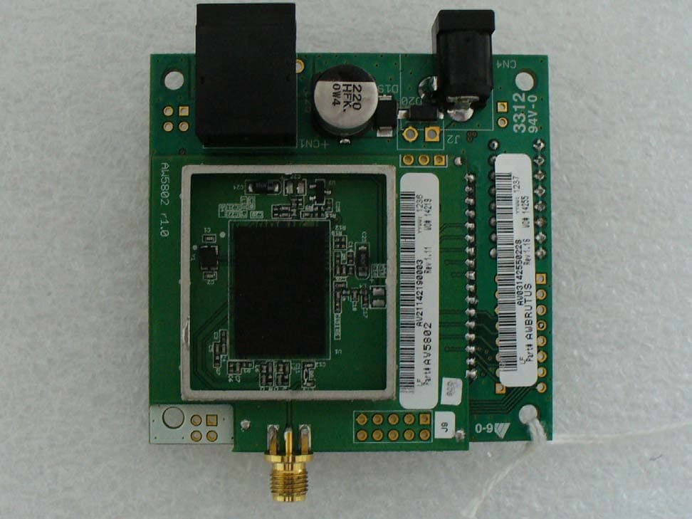
R4N-AW5802MR
Dec 17, 2012AW5802MR
Equipment Class
DTS - Digital Transmission System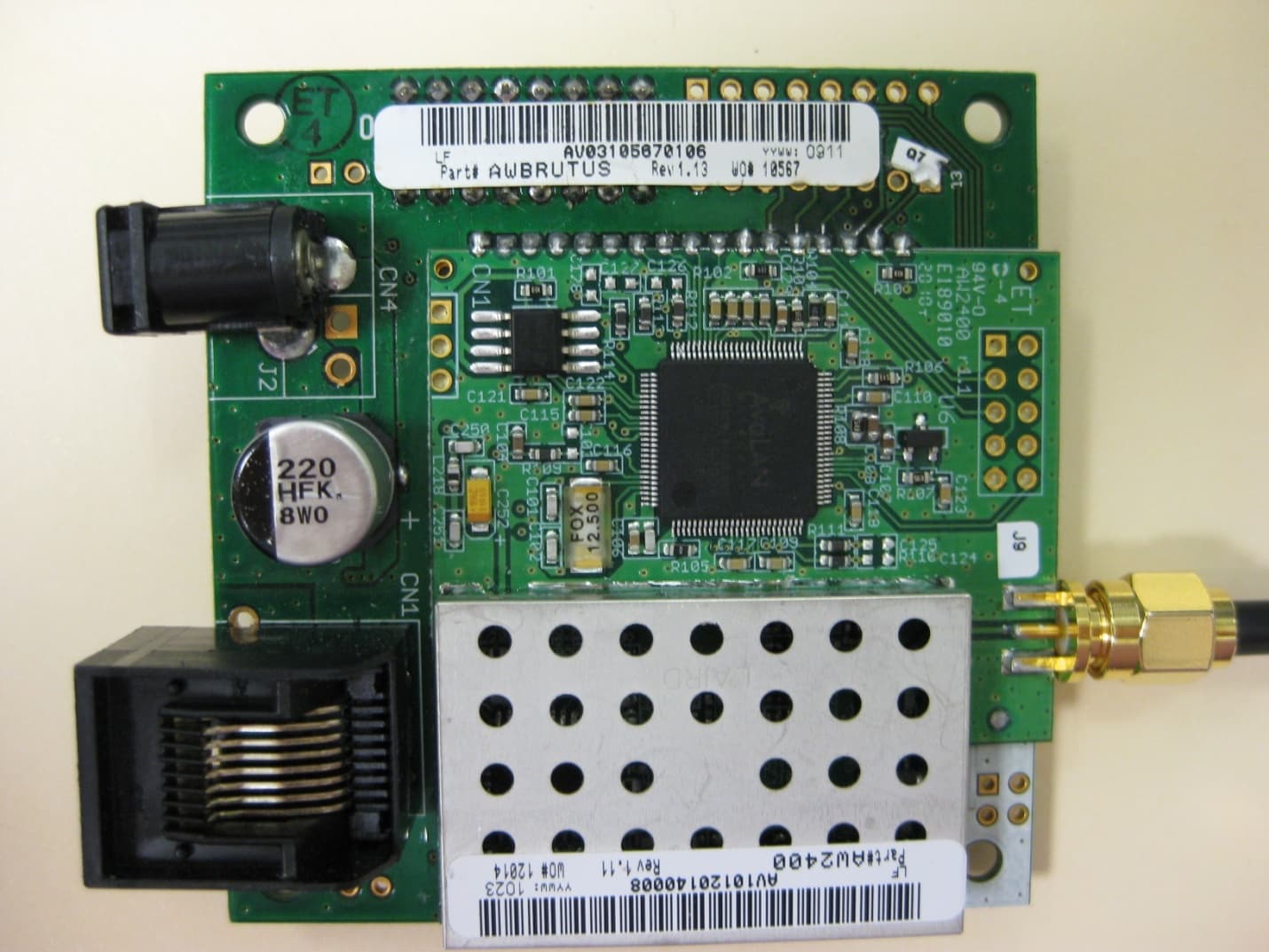
R4N-AW2400MR
Nov 08, 20102.4 GHz Wireless Ethernet Module
Equipment Class
DTS - Digital Transmission System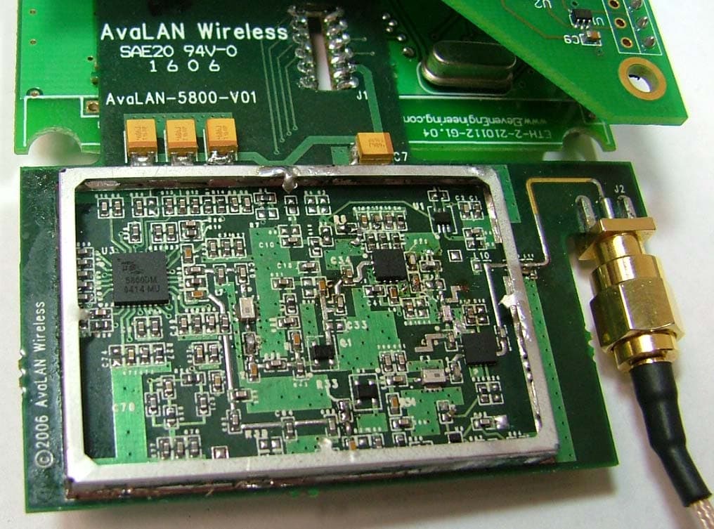
R4N-AW5800M
Jul 19, 20065.8GHz Wireless Ethernet Bridge Module
Equipment Class
DTS - Digital Transmission System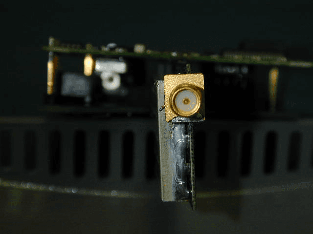
R4N-AW900M
Sep 08, 2005Ethernet Bridge Transmitter Module
Equipment Class
DTS - Digital Transmission System