R8KUGWT1BL1TETRA Dual Mode Bluetooth Radio Module
Unigen Corporation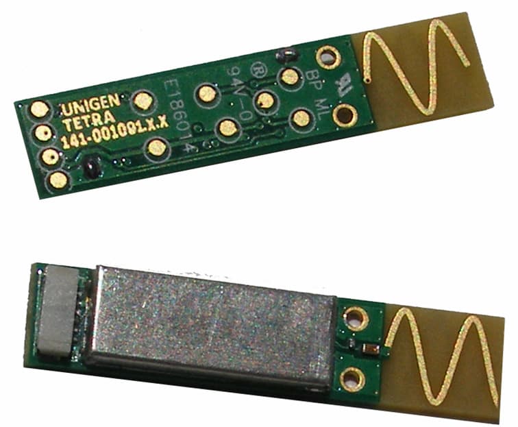
Click to zoom
Application Details
- Equipment Class
- DSS - Part 15 Spread Spectrum Transmitter
- Date of Grant
- Jan 26, 2012
- Application Purpose
- Original Equipment
- Date of Application
- Jan 26, 2012
- Equipment Note
- TETRA Dual Mode Bluetooth Radio Module
- Frequency Range
- 2402.00000000 - 2480.00000000
- Company
- Unigen Corporation
- Country
- United States
Documents & Files
Document Text
Text extracted from the exhibit documents filed with the FCC. Open a document above to read the original.
Users Manual
TETRA Bluetooth Radio Module Solutions for a Real Time World Datasheet Re-Tek - xxxx - 1 - 45388 Warm Springs Blvd. Fremont, CA 94539 [email protected] TEL: (510) 668.2088 FAX: (510) 661.2788 http://www.unigen.com Customer Comment Line: (800) 826.0808 Copyright Unigen Corporation, 2011 Unigen Corp. Wireless Module Products TETRA Dual Mode Bluetooth Radio Module UGWT1BL2FLA233A Issue Date: 01-Dec-11 Revision: 0.1a TETRA Bluetooth Radio Module Solutions for a Real Time World Datasheet Re-Tek - xxxx - 2 - 45388 Warm Springs Blvd. Fremont, CA 94539 [email protected] TEL: (510) 668.2088 FAX: (510) 661.2788 http://www.unigen.com Customer Comment Line: (800) 826.0808 Copyright Unigen Corporation, 2011 Revision History Rev. No. History Issue Date Remarks 0.1 Draft Dec. 11, 2011 Advanced information; Author: Allen B. Cabreros 0.1a - Jan. 23, 2012 FCC Compliance/Warning statement added This document is provided “as is” with no warranties whatsoever, including any warranty of merchantability, non-infringement, fitness for any particular purpose, or any warranty otherwise arising out of any proposal, specification or sample. Unigen Corporation disclaims all liability, including liability for infringement of any proprietary rights, relating to use of information in this document. No license, expressed or implied, by estoppel or otherwise, to any intellectual property rights is granted herein. *Third-party brands, names, and trademarks are the property of their respective owners. TETRA Bluetooth Radio Module Solutions for a Real Time World Datasheet Re-Tek - xxxx - 3 - 45388 Warm Springs Blvd. Fremont, CA 94539 [email protected] TEL: (510) 668.2088 FAX: (510) 661.2788 http://www.unigen.com Customer Comment Line: (800) 826.0808 Copyright Unigen Corporation, 2011 TABLE OF CONTENTS LIST OF FIGURES __________________________________________ 3 LIST OF TABLES ___________________________________________ 4 PRODUCT INTRODUCTION ___________________________________ 5 FEATURES AND BENEFITS ____________________________________ 5 PRODUCT DESCRIPTION _____________________________________ 7 TETRA Module __________________________________________ 7 CSR Bluetooth Controller IC _______________________________ 7 Functional Block Diagram _________________________________ 8 CONNECTOR PIN ASSIGNMENT _______________________________ 9 PIN FUNCTIONS ___________________________________________ 10 ABSOLUTE MAXIMUM RATINGS _______________________________ 11 RECOMMENDED OPERATING CONDITIONS ______________________ 11 RF CHARACTERISTICS ______________________________________ 12 AGENCY CERTIFICATIONS (PRE-SCAN) _________________________ 13 FCC REGULATORY COMPLIANCE STATEMENT _____________________ 13 BLUETOOTH COMPLIANCE ___________________________________ 13 TBDFUNCTIONAL OVERVIEW _________________________________ 13 FUNCTIONAL OVERVIEW ____________________________________ 14 TETRA Hardware Functional Description ______________________ 14 BLUETOOTH SOFTWARE STACK _______________________________ 15 Key Features of the HCI Stack ______________________________ 16 USB INTERFACE ___________________________________________ 18 POWER CONSUMPTION _____________________________________ 18 MECHANICAL DRAWINGS ____________________________________ 20 CONTACT INFORMATION ____________________________________ 21 LIST OF FIGURES Figure 1: TETRA Module Block Diagram _________________________ 8 Figure 2: TETRA Pin Location and Descriptions ____________________ 9 Figure 3: TETRA Bluetooth HCI Stack ___________________________ 15 Figure 4: TETRA Mechanical Drawing ___________________________ 20 TETRA Bluetooth Radio Module Solutions for a Real Time World Datasheet Re-Tek - xxxx - 4 - 45388 Warm Springs Blvd. Fremont, CA 94539 [email protected] TEL: (510) 668.2088 FAX: (510) 661.2788 http://www.unigen.com Customer Comment Line: (800) 826.0808 Copyright Unigen Corporation, 2011 LIST OF TABLES TABLE 1: TETRA PIN FUNCTIONS ______________________________ 10 TABLE 2: ABSOLUTE MAXIMUM RATINGS ________________________ 11 TABLE 3: RECOMMENDED OPERATING CONDITIONS _______________ 11 TABLE 4: RF CHARACTERISTICS _______________________________ 12 TABLE 5: OPERATING POWER CONSUMPTION FIGURES ____________ 18 TABLE 6: PEAK CURRENT ____________________________________ 19 TETRA Bluetooth Radio Module Solutions for a Real Time World Datasheet Re-Tek - xxxx - 5 - 45388 Warm Springs Blvd. Fremont, CA 94539 [email protected] TEL: (510) 668.2088 FAX: (510) 661.2788 http://www.unigen.com Customer Comment Line: (800) 826.0808 Copyright Unigen Corporation, 2011 PRODUCT INTRODUCTION The Tetra module supports Bluetooth v4.0 for the Low Energy operation and Bluetooth v3.0 + High Speed * for communication with existing Bluetooth devices. Tetra operates on the High Speed (+HS) bandwidth via a XSR six pin JST connector. The interface is the USB HCI protocol. Tetra utilizes a serial EEPROM for retaining the Bluetooth Address, Country Code of operation, and previously paired Bluetooth devices. It stores the Bluetooth address and link key information on the module. The slim design of Tetra features on-board, double helix, printed, antenna which addresses many antenna placement issues. The module is designed to be placed in areas that are small and slim offering optimum antenna placement. Also, instead of using RF cable assemblies and/or external antenna, the module can be placed using a low cost 6 wire cable assembly which is used to connect the module to the motherboard and host. F EATURES AND BENEFITS Dual Mode Bluetooth, V3.0+HS, V4.0, BLE Programmable EEPROM Full Speed USB 2.0 Protocol Interface Double Helix Printed PCB Antenna +9dBm Transmit Power; -90dBm Receive Sensitivity Dimensions: 30mm x 6.5mm x 2.25mm 6 pin XSR JST Low Profile Connector LED Driver Deep Sleep Mode of 40μA With Fast Wake-up Range up to 35 meters * Bluetooth High Speed is dependent on the Bluetooth Stack on the Host. TETRA Bluetooth Radio Module Solutions for a Real Time World Datasheet R…
Text truncated - open the document above for the full version.
Attestation Statements
TRL 51F047 iss02B LETTER OF AGENCY To Whom It May Concern: We certify that we are not subject to denial of federal benefits, that includes FCC benefits, pursuant to Section 5301 of the Anti-Drug Abuse ACT of 1988, U.S.C. 862. Further, no party, as defined in 47 CFR 1.2002(b), to the application, is subject to denial of federal benefits, that includes FCC benefits. Thank you for your attention to this matter. Thank you for your attention to these matters. Yours faithfully Unigen Corporation Weerapol Seesanung
Cover Letter(s)
TRL 51F050 iss02B Confidentiality Request Details of the confidentiality rules are below. The letter that needs to be completed and returned is on page 2 (this relates to permanent confidentiality only). Letter of confidentiality (Permanent Confidentiality) If exhibits are to remain confidential then a request letter should form part of the submission. The letter should request confidentiality pursuant to rule part 0.459 and should list the specific exhibits that are to remain confidential. The following Exhibits can be retained for long term confidentiality: Parts list / Bill of Materials Schematic Diagrams Operational Description Radio RF Block Diagram In addition to the above, the user manual can be retained as confidential if it is very technical and not supplied to the end user but to service personnel and professional installers. The internal photographs can remain confidential if the product will be fully potted in use Letter of confidentiality (Temporary Confidentiality) An exhibit that is classed as business sensitive can be held temporarily confidential for a period up to 180 days if the product is not being marketed in the US. The temporary confidentiality is valid initially for 45 days at which point an additional declaration will be required to extend for a further 45 days and so on. Failure to submit additional declarations will result in the temporary confidentiality being automatically removed at the end of the 45 day period. As soon as the product begins to be marketed the TCB should be informed and any exhibits held temporarily confidential will revert to public domain. Failure to inform the TCB at the marketing stage will be in violation of FCC regulations and the FCC could take further action. A letter of requesting temporary confidentiality will be required, this should include the reasons the exhibit(s) are to be held confidential and a declaration stating that the product is not being marketed in the US. The following exhibits are eligible for short term confidentiality. Internal Photos External Photos Test setup photos User Manual TRL 51F050 iss02B REQUEST FOR CONFIDENTIALITY IN ACCORDANCE WITH FCC RULE 0.459 23 January 2012 TRaC Global 100 Frobisher Business Park Leigh Sinton Road Malvern Worcestershire WR14 1BX UK RE: Certification Application FCC ID: R8KUGWT1BL1 To Whom It May Concern: Please be advised that the following information is to be held confidential on behalf of Unigen Corporation • Parts list / Bill of Materials • Schematic Diagrams • Operational Description • Radio RF Block Diagram The application contains technical information which Invisible Systems Ltd deems to be trade secrets and propriety. If made public, the information might be used to the disadvantage of the applicant in the market place. Thank you for your attention to this matter. Yours faithfully Unigen Corporation Full Name: Weerapol Seesanung
Cover Letter(s)
MODULAR APPROVAL REQUEST Date 23/01/2012 TRaC Global 100 Frobisher Business Park Leigh Sinton Road Malvern Worcestershire WR14 1BX UK RE: FCC Modular Approval FCC ID: R8KUGWT1BL1 To Whom It May Concern: Please be advised that the manufacturer requests that the above-referenced model be approved for modular approval in accordance with the FCC Rules and Regulations. Thank you for your attention to this matter. Yours faithfully Unigen Corporation Signature Full Name: Weerapol Seesanung
Cover Letter(s)
Date 2410112012 TRaCGlobal 100 Frobisher Business Park Leigh Sinton Road Malvem Worcestershire WR141BX UK HOPPING PROTOCOLS DECLARATION RE: FCC Hopping Protocols Declaration FCC ID: R8KUGWT1 BL 1 To Whom It May Concem: Please be advised that our product meets the hopping protocols set out in FCC CFR 47 part 15.247. The product is an 802.15.4 Bluetooth Equipment and therefore by default complies with the requirements of 15.247 Yours faithfully Unigen Corporation ~~~ Signature ------ Full Name ALLEN CABREROS
ID Label/Location Info
PIWBLUESLIM2 Model: ‐ BLUESLIM2 PIWBLUESLIM2 5255A ‐ BLUESLIM2 2010DJ6579 Label on Module. EC No: FRU P/N: Made in Ta i w a n Made in Ta i w a n FRU P/N: Bottom of laptop. Label location.
Test Report
Total number of pages : 77 TRaC Wireless Test Report:TTR-001914WUS1 Applicant:CSR Inc Apparatus:BlueSlim 2 Bluetooth Module Specification(s):CFR47 Part 15.247 July 2008 FCCID:PIW-BLUESLIM2 Purpose of Test: CERTFICATION Authorised by: : Radio Product Manager Issue Date:14 th January 2011 Authorised Copy Number: PDF Radio Test Report: TTR-001914WUS1 2 Contents Section 1:Introduction3 1.1General3 1.2Tests Requested By4 1.3Manufacturer4 1.4Apparatus Assessed4 1.5Test Result Summary5 1.6Notes Relating To The Assessment6 1.7Deviations from Test Standards6 Section 2:Measurement Uncertainty7 2.1Application of Measurement Uncertainty7 2.2Measurement Uncertainty Values8 Section 3:Modifications10 3.1Modifications Performed During Assessment10 Appendix A:Formal Emission Test Results11 A1Transmitter Peak Output Power12 A2RF Antenna Conducted Spurious Emissions13 A3Radiated Electric Field Emissions Within The Restricted Bands of 15.20515 A420 dB Bandwidth20 A5Carrier Frequency Separation21 A6Hopping frequencies22 A7Channel Occupancy23 A8Antenna Gain24 A9Unintentional Radiated Electric Field Emissions - 15.10925 Appendix B:Supporting Graphical Data28 Appendix C: Additional Test and Sample Details64 Appendix D:Additional Information70 Appendix E:Calculation of the duty cycle correction factor71 Appendix F:Photographs and Figures72 Appendix G:MPE Calculation76 Radio Test Report: TTR-001914WUS1 3 Section 1:Introduction 1.1General This report contains an assessment of an apparatus against Electromagnetic Compatibility Standards based upon tests carried out on samples submitted to the Laboratory. Test performed by:TRaC Telecoms & Radio[ ] Unit E South Orbital Trading Park Hedon Road Hull, HU9 1NJ. United Kingdom. Telephone:+44 (0) 1482 801801 Fax:+44 (0) 1482 801806 TRaC Telecoms & Radio[X] Moss View Nipe Lane Up Holland West Lancashire, WN8 9PY United Kingdom Telephone:+44 (0) 1695 556666 Fax:+44 (0) 1695 577077 Email:[email protected] Web site:http://www.tracglobal.com Tests performed by:Steven Hodgkinson Report author:Steven Hodgkinson This report mustnot be reproduced except in full without prior written permission from TRaC Telecoms & Radio. Radio Test Report: TTR-001914WUS1 4 1.2Tests Requested By This testing in this report was requested by : CSR Inc. 2425 N Central Expressway Suite 1000 Richardson Texas USA 75080 1.3Manufacturer As Above 1.4Apparatus Assessed The following apparatus was assessed between 13/12/10 and12/1/11 BlueSlim 2 Bluetooth Module The above equipment was a FHSS transmitter operating in the 2400 MHz to 2483.5MHzband and is a Bluetooth module, designed for use internal to a laptop and used to enable Bluetooth wireless communication within personal computers and laptops. Radio Test Report: TTR-001914WUS1 5 1.5Test Result Summary Full details of test results are contained within Appendix A. The following table summarises the results of the assessment. The statements relating to compliance with the standards below apply ONLY as qualified in the notes and deviations stated in sections 1.6 to 1.7 of this test report. Full details of test results are contained within Appendix A. The following table summarises the results of the assessment. Test TypeRegulation Measurement standard Result Radiated spurious emissions (Restricted bands) Title 47 of the CFR: Part 15 Subpart (c) 15.247 ANSI C63.10PASS Conducted spurious emissions (Non-restricted bands) Title 47 of the CFR: Part 15 Subpart (c) 15.247 ANSI C63.10PASS AC Power conducted emissions Title 47 of the CFR: Part 15 Subpart (c) 15.207 ANSI C63.10N/A 20dB Bandwidth and Channel Spacing Title 47 of theCFR : Part 15 Subpart (c) 15.247(a)(1)(i) ANSI C63.10PASS Conducted Carrier Power Title 47 of the CFR : Part 15 Subpart (c) 15.247(b)(2) ANSI C63.10PASS Hopping Frequencies Title 47 of the CFR : Part 15 Subpart (c) 15.247(a)(1) ANSI C63.10PASS Channel Occupancy Title 47 of the CFR : Part 15 Subpart (c) 15.247(a)(1)(i) ANSI C63.10PASS Unintentional Radiated Spurious Emissions Title 47 of the CFR: Part 15 Subpart (b) 15.109 ANSI C63.10PASS Abbreviations used in the above table: Mod: Modification CFR: Code of Federal RegulationsANSI: American National Standards Institution REFE: Radiated Electric Field EmissionsPLCE: Power Line Conducted Emissions Radio Test Report: TTR-001914WUS1 6 1.6Notes Relating To The Assessment With regard to this assessment, the following points should be noted: The results contained in this report relate only to the items tested and were obtained in the period between the date of initial receipt of samples and the date of issue of the report. The apparatus was set up and exercised using the configurations, modes of operation and arrangements defined in this report only. Particular operating modes, apparatus monitoring methods and performance criteria required by the standards tested to have been performed except where identified in Section 1.7 of this test report (Deviations from Test Standards). For emissions testing, throughout this test report, “Pass” indicates that the results for the sample as tested were below the specified limit (refer also to Section 2, Measurement Uncertainty). Where relevant, the apparatus was only assessed using the monitoring methods and susceptibility criteria defined in this report. All testing with the exception of testing at the Open Area Test Site was performed under the following environmental conditions: Temperature: 17 to 23 C Humidity : 45 to 75 % Barometric Pressure: 86 to 106 kPa All dates used in this report are in the format dd/mm/yy. This assessment has been performed in accordance with the requirements of ISO/IEC 17025. 1.7Deviations from Test Standards There were no deviations from the standards tested to. Radio Test Report: TTR-001914WUS1 7 Section 2:Measurement Uncertainty 2.1Application of Measurement Uncertainty The following table contains the measurement uncertainties for measurements The measured value related to the corresponding limit is used to decide whether equ…
Text truncated - open the document above for the full version.
Contact Information
Applicant
weerapol seesanung(Wireless Test Engineer)
Test Firm
Element Materials Technology Warwick LtdKeith Wright
Technical Specifications
| # | Rule Parts | Frequency Range | Power Output |
|---|---|---|---|
| 1 | 15C | 2.40 GHz - 2.48 GHz | 3.54 mW |
Other Applications from Unigen Corporation
R8KUGWSX931
Nov 25, 2012900MHz Transceiver Module
Equipment Class
DTS - Digital Transmission System
R8KUGWC821R
Jun 14, 2012NEMO BLUETOOTH RADIO MODULE
Equipment Class
DSS - Part 15 Spread Spectrum Transmitter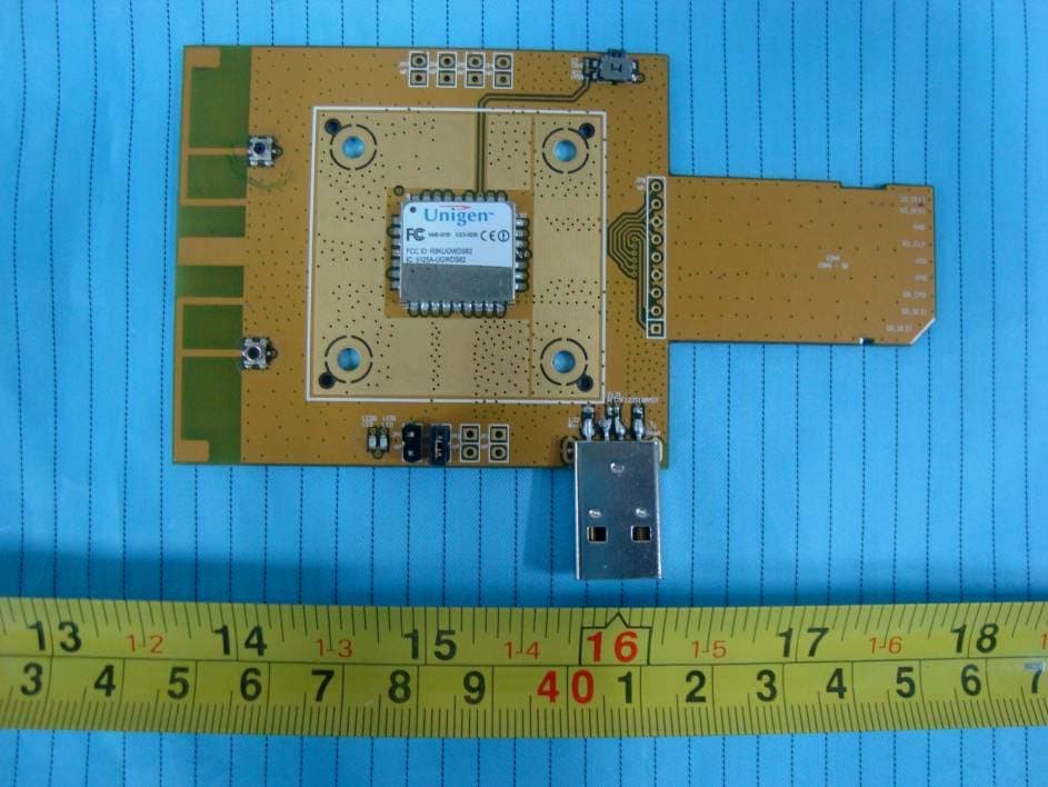
R8KUGWDS82
Jun 17, 2010802.11b/g/n WiFi Radio Module
Equipment Class
DTS - Digital Transmission System
R8KUGQUBE1US
Dec 29, 2005USB Dongle
Equipment Class
DTS - Digital Transmission System
R8KUGWN2USHN33
Aug 24, 20052.4GHz Wireless Module
Equipment Class
DTS - Digital Transmission System