R932033500KEY CAPTAIN REMOTE LAUNCHING SYSTEM-RECEIVER
Delta Systems INC.
Click to zoom
Application Details
- Equipment Class
- CYY - Communications Receiver used w/Pt 15 Transmitter
- Date of Grant
- Mar 21, 2006
- Application Purpose
- Original Equipment
- Date of Application
- Mar 21, 2006
- Equipment Note
- KEY CAPTAIN REMOTE LAUNCHING SYSTEM-RECEIVER
- Frequency Range
- 433.92000000 - 433.92000000
- Company
- Delta Systems INC.
- Country
- United States
Documents & Files
Document Text
Text extracted from the exhibit documents filed with the FCC. Open a document above to read the original.
Users Manual
Sarasota Quality Products • 27330 Center Ridge Road •Westlake • Ohio 44145 Ph: (440) 899-9820 ● Fx: (440) 899-0930 ● www.sarasotaqp.com 1 PRELIMINARY Key Captain™ Remote Launching System Installation Instructions Sarasota Quality Products is a provider of security/access products for the marine market. Products are designed to secure personal effects and equipment, while providing safety, convenience, and launch assistance for many types of watercraft. PLEASE SAVE THESE INSTRUCTIONS FEATURES: Key Captain™ is a Remote Launching System that provides time saving remote control launch functions for most boats. • Lock & Unlock Compartment Latches • Turn Bilge Blowers On & Off • Trim Down & Up (Trailer Or Storage Position) • Operate Auxiliary Functions (Cabin Lighting, Etc.) • Designed For Easy Installation • Corrosion Resistant Materials Used Throughout • Unique System Sleep Mode • Low Power Saving Operation That Extends Battery Life • Floating Waterproof Remote Transmitter(s) • On Site Programmable Remote Transmitter(s) • Permanently Sealed Control Panel • Audible Sounder Indicates System Operations • FCC Compliant SYSTEM COMPONENTS CONTROL PANEL FLOAT REMOTE TRANSMITTER SELS ELECTRIC LOCK LATCH WARNING: Read and understand these instructions thoroughly before proceeding with installation. Improper installation may result in incorrect operation of the system. 9 To prevent personal injury, always disconnect the battery leads when installing or servicing this product. 9 Power source must match the voltage rating of this product. 9 Always use a fuse with amperage rating specified for this system. Failure to do so may result in serious personal injury or fire hazard. Power Specification (Key Captain™ Control Panel) Circuit Voltage Operating Current Battery (Standby 15MA.) 9 – 16VDC 20 Amp Lock 9 – 16VDC 10 Amp Unlock 9 – 16VDC 10 Amp Trim Up (see note) 9 – 16VDC 5 Amp Trim Down (see note) 9 – 16VDC 5 Amp Bilge Blower (see note) 9 – 16VDC 5 Amp Note: Use BASIC WIRING INSTRUCTIONS except when current requirements exceed fuse ratings shown, then, use ALTERNATE WIRING INSTRUCTIONS. Power Specification (Key Captain™ Electric Lock/Latches) Circuit Voltage Current Lock connection (Lt. Blue) 9 – 16VDC 0.5 Amp Unlock connection (White.) 9 – 16VDC 0.5 Amp Power Specification (Key Captain™ Transmitter) Circuit Voltage Battery # 2 Coin Cell batteries 1.5 VDC ea. CR-2 REQUIRED FOR INSTALLATION • Drill and suitable drill bit • Hole saw • Screwdriver • Wire cutter/striper • Crimp on wire connectors for 12, 16, & 18 gauge wire • Cable tie-wraps • Suitable stainless steel pan head screws • Fuses as required • Fuse holder for above fuses • 12, 16, 18 gauge wire INSTALLATION MUST MEET APPLICABLE SECTIONS OF TITLE 33 CFR 183 SUBPART I, USCG REGULATIONS. To prevent personal injury, always disconnect the battery leads when installing the control panel, electric lock latches or connections to auxiliary function devices. The Key Captain™ control panel is designed for easy installation. See separate installation instructions for mounting of Key Captain™ electrical lock latches. MOUNTING INSTRUCTIONS 1. The Key Captain™ control panel may be positioned near the helm, and in a secure area. The control panel may be secured to any solid, flat mounting surface and oriented in any direction. 2. For security protection, the control panel should be mounted inside a lockable compartment or other secure area. 3. For maximum reception of signals from the transmitter to the control panel it should be located close to top level of the boat (see Fig. 1). It should be mounted within 10 inches of a fuse distribution panel (furnished by others). 4. Using the control panel as a template, mark holes for mounting feet and drill holes. Secure control panel in place taking care not to over tighten screws or penetrate hull. BASIC WIRING INSTRUCTIONS Note: Use BASIC WIRING INSTRUCTIONS except when current requirements exceed fuse ratings shown in Power Specification (Key Captain™ Control Panel), then, use ALTERNATE WIRING INSTRUCTIONS. 1. Connect Key Captain™ control panel wires to fuse distribution box: (Fig 2) 2. Connect control panel negative (green) wire to a good chassis ground or negative post of battery (Fig. 2) 3. Use a quality marine grade stranded copper wire and connect from fuse distribution box to the following circuits: (Fig 2) 4. Connect positive (+) battery (red) control panel circuit from fuse distribution panel to the boat +12VDC battery post (Fig. 2). 5. Connect lock (light blue) control panel circuit wire from fuse distribution panel to SELS 1000 electrical lock latches. Observe polarity of wiring to connect to all light blue wires (Fig. 2) 6. Connect unlock (white) control panel circuit wire from fuse distribution panel to SELS 1000 electrical lock latches. Observe polarity of wiring to connect all white wires together (Fig. 2) 7. Connect trim down (pink) control panel circuit wire from fuse distribution panel to trim down circuit input on trim controller (Fig. 2) 8. Connect trim/trailer up (orange) control panel circuit wire from fuse distribution panel to trim/trailer up circuit input on trim controller (Fig. 2) Sarasota Quality Products • 27330 Center Ridge Road •Westlake • Ohio 44145 Ph: (440) 899-9820 ● Fx: (440) 899-0930 ● www.sarasotaqp.com 9. Connect bilge blower (brown) control panel circuit wire from fuse distribution panel to +12VDC wire on bilge blower (Fig. 2) 10. Do not make any connection to black wire on the Key Captain™ control panel. This is the antenna wire and it is to hang freely (Fig. 2) OPERATING INSTRUCTIONS Float Remote™ Transmitters control the operation/functions of the Key Captain™ system. The operating range is 25-30 feet with direct line of sight between the transmitter and control panel. The effective range may diminish if direct line of sight is not available. Five function buttons are located on top of the Transmitter. Lock and Un-Lock operations are accomplished by momentarily pressing the …
Text truncated - open the document above for the full version.
External Photos
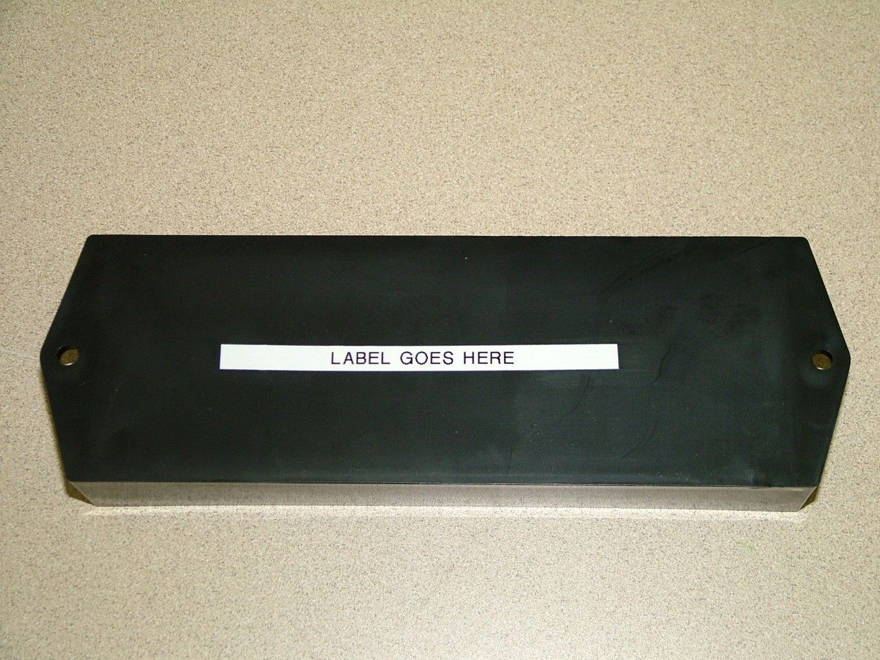
DELTA SYSTEMS, INC. FCC ID: R932033500 EXTERNAL PHOTOS
Internal Photos
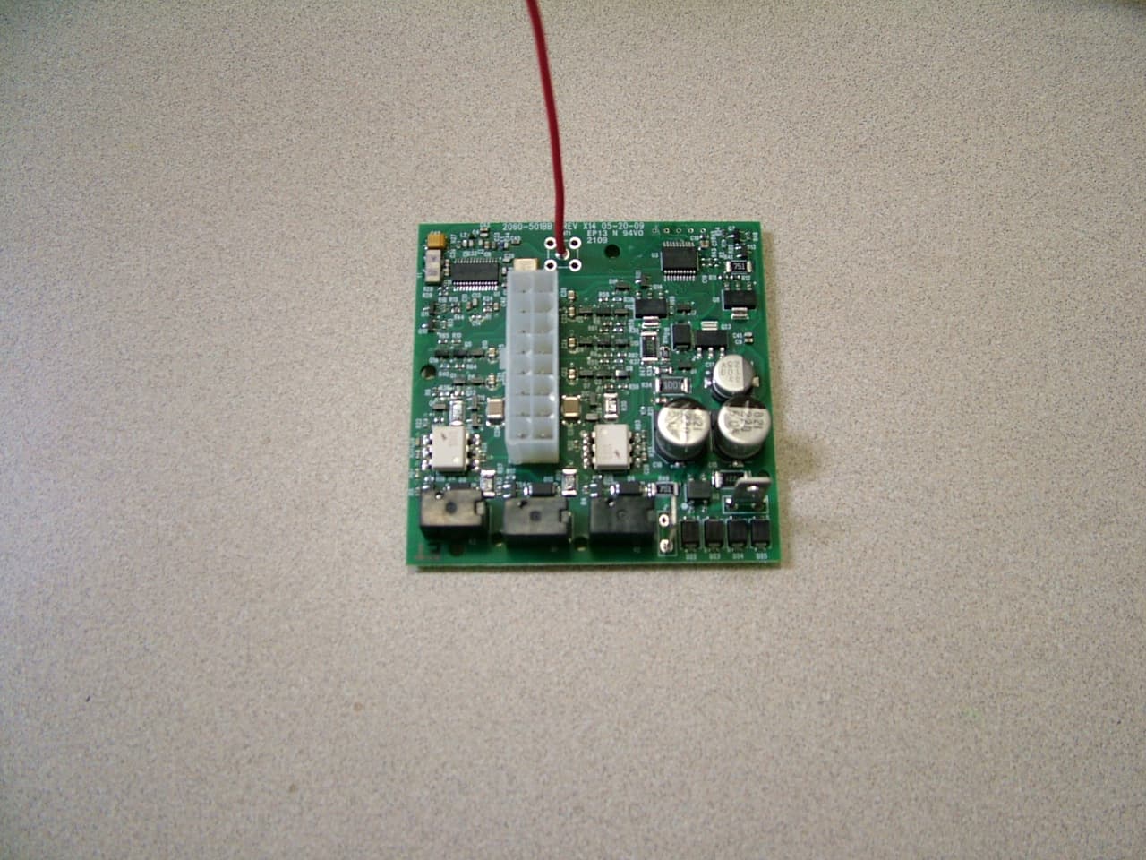
DELTA SYSTEMS, INC. FCC ID: R932033500 INTERNAL PHOTOS
Test Report
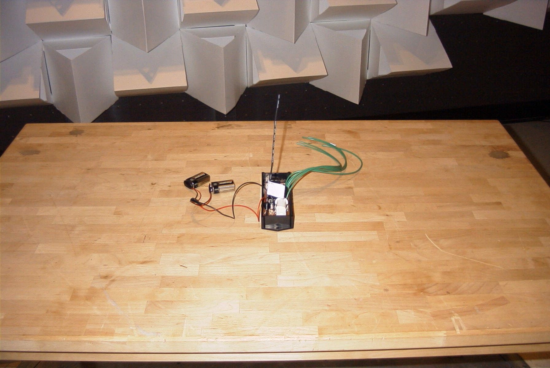
TIMCO ENGINEERING INC. 849 NW State Road 45 Newberry, Florida 32669 http://www.timcoengr.com 888.472.2424 F 352.472.2030 email: [email protected] APPLICANT: DELTA SYSTEMS INC. FCC ID: R932033500 REPORT #: D\DELTA SYSTEMS\466AUT6\466AUT6TestReport.doc COVER SHEET Test Report Product Name: KEY CAPTAIN REMOTE LAUNCHING SYSTEM - RECEIVER FCC ID: R932033500 Applicant: DELTA SYSTEMS INC. 10036 AURORA - HUDSON ROAD 1734 FROST ROAD STREETSBORO OH 44241 USA Date Receipt: 3/6/2006 Date Tested: 3/6/2006 TIMCO ENGINEERING INC. 849 NW State Road 45 Newberry, Florida 32669 http://www.timcoengr.com 888.472.2424 F 352.472.2030 email: [email protected] APPLICANT: DELTA SYSTEMS INC. FCC ID: R932033500 REPORT #: D\DELTA SYSTEMS\466AUT6\466AUT6TestReport.doc TABLE OF CONTENTS TABLE OF CONTENTS LIST APPLICANT: DELTA SYSTEMS INC. FCC ID: R932033500 TEST REPORT CONTAINING: PAGE 1...............TEST EQUIPMENT LIST PAGE 2...............TEST PROCEDURES PAGE 3...............RADIATION INTERFERENCE TEST DATA EXHIBITS CONTAINING: REQUEST FOR CONFIDENTIALITY LETTER BLOCK DIAGRAM SCHEMATIC INSTRUCTION MANUAL LABEL SAMPLE LABEL LOCATION EXTERNAL PHOTOGRAPHS INTERNAL PHOTOGRAPHS CIRCUIT DESCRIPTION TEST SET UP PHOTOGRAPH TIMCO ENGINEERING INC. 849 NW State Road 45 Newberry, Florida 32669 http://www.timcoengr.com 888.472.2424 F 352.472.2030 email: [email protected] APPLICANT: DELTA SYSTEMS INC. FCC ID: R932033500 REPORT #: D\DELTA SYSTEMS\466AUT6\466AUT6TestReport.doc Page 1 of 3 EMC Equipment List Device Manufacturer Model Serial Number Cal/Char Date Due Date 3/10-Meter OATS TEI N/A N/A Listed 3/27/04 3/26/07 3-Meter OATS TEI N/A N/A Listed 1/11/06 1/10/09 Biconnical Antenna Eaton 94455-1 1057 CAL 12/12/05 12/12/07 Biconnical Antenna Eaton 94455-1 1096 CAL 8/17/04 8/17/06 Biconnical Antenna Electro- Metrics BIA-25 1171 CAL 4/29/05 4/29/07 Blue Tower Quasi-Peak Adapter HP 85650A 2811A01279 CAL 4/13/05 4/13/07 Blue Tower RF Preselector HP 85685A 2926A00983 CAL 9/5/05 9/5/07 Blue Tower Spectrum Analyzer HP 8568B 2928A04729 2848A18049 CAL 4/13/05 4/13/07 LISN Electro- Metrics ANS-25/2 2604 CAL 8/27/04 8/27/06 LISN Electro- Metrics EM-7820 2682 CAL 4/28/05 4/28/07 Log- Periodic Antenna Eaton 96005 1243 CAL 12/14/05 12/14/07 TIMCO ENGINEERING INC. 849 NW State Road 45 Newberry, Florida 32669 http://www.timcoengr.com 888.472.2424 F 352.472.2030 email: [email protected] APPLICANT: DELTA SYSTEMS INC. FCC ID: R932033500 REPORT #: D\DELTA SYSTEMS\466AUT6\466AUT6TestReport.doc Page 2 of 3 TEST PROCEDURE GENERAL: This report shall NOT be reproduced except in full without the written approval of TIMCO ENGINEERING, INC. RADIATION INTERFERENCE: The test procedure used was ANSI STANDARD C63.4-2003 using a HEWLETT PACKARD spectrum analyzer with a preselector. The bandwidth of the spectrum analyzer was 100 kHZ with an appropriate sweep speed. The analyzer was calibrated in dB above a microvolt at the output of the antenna. The resolution bandwidth was 100KHZ and the video bandwidth was 300KHZ. The ambient temperature of the UUT was 80ºF with a humidity of 70%. FORMULA OF CONVERSION FACTORS: The Field Strength at 3m was established by adding the meter reading of the spectrum analyzer (which is set to read in units of dBuV) to the antenna correction factor supplied by the antenna manufacturer. The antenna correction factors are stated in terms of dB. The gain of the Preselector was accounted for in the Spectrum Analyzer Meter Reading. Example: Freq (MHz) METER READING + ACF = FS 33 20 dBuV + 10.36 dB = 30.36 dBuV/m @ 3m ANSI STANDARD C63.4-2003 10.1.7 MEASUREMENT PROCEDURES: The unit under test was placed on a table 80 cm high and with dimensions of 1m by 1.5m. The table used for radiated measurements is capable of continuous rotation. When an emission was found, the table was rotated to produce the maximum signal strength. At this point, the antenna was raised and lowered from 1m to 4m. The antenna was placed in both the horizontal and vertical planes. TIMCO ENGINEERING INC. 849 NW State Road 45 Newberry, Florida 32669 http://www.timcoengr.com 888.472.2424 F 352.472.2030 email: [email protected] APPLICANT: DELTA SYSTEMS INC. FCC ID: R932033500 REPORT #: D\DELTA SYSTEMS\466AUT6\466AUT6TestReport.doc Page 3 of 3 APPLICANT: DELTA SYSTEMS INC. FCC ID: R932033500 NAME OF TEST: RADIATION INTERFERENCE RULES PART NO.: 15.109 REQUIREMENTS: 30 to 88 MHz: 40.0 dBuV/M @ 3 METERS 88 to 216 MHz: 43.5 dBuV/M 216 to 960 MHz: 46.0 dBuV/M ABOVE 960 MHz: 54.0 dBuV/M TEST RESULTS: A search was made of the spectrum from 30 to 1000MHz and the measurements indicate that the unit DOES meet the FCC requirements. TEST DATA: Tuned Frequency MHz Emission Frequency MHz Meter Reading dBuV Ant. Pol Coax Loss dB Correction Factor dB Field Strength dBuV/m Margin dB 433.9 432.90 5.8 H 1.23 16.59 23.62 22.38 433.9 432.90 6.6 V 1.23 16.16 23.99 22.01 433.9 438.60 5.4 V 1.24 16.27 22.91 23.09 433.9 438.60 6.4 H 1.24 16.76 24.40 21.60 433.9 865.80 6.6 H 1.93 22.92 31.45 14.55 433.9 865.80 8.8 V 1.93 22.40 33.13 12.87 Emissions attenuated more than 20 dB below the permissible value are not reported. SAMPLE CALCULATION: FSdBuV/m = MR (dBuV) + ACFdB. TEST PROCEDURE: ANSI STANDARD C63.4-2003 using a Hewlett Packard Model 8566B spectrum analyzer, a Hewlett Packard Model 85685A Preselector, a Hewlett Packard Model 85650A Quasi-Peak adapter, and an appropriate antenna – see the test equipment list. The bandwidth of spectrum analyzer was 100 kHz with an appropriate sweep speed. When an emission was found, the table was rotated to produce the maximum signal strength. The antenna was placed in both the horizontal and vertical planes and the worse case emissions were reported. PERFORMED BY: JOSEPH SCOGLIO DATE:03/07/2006
Contact Information
Applicant
Chop Kramer(RF Enginreer)
Test Firm
Timco Engineering, Inc.Sid Sanders
Technical Specifications
| # | Rule Parts | Frequency Range | Power Output |
|---|---|---|---|
| 1 | 15B | 433.92 MHz - 433.92 MHz | - |
Other Applications from Delta Systems INC.
R932060500
Jul 23, 2009915 MHz REMOTE CONTROL RECEIVER
Equipment Class
CXX - Communications Rcvr for use w/ licensed Tx and CBs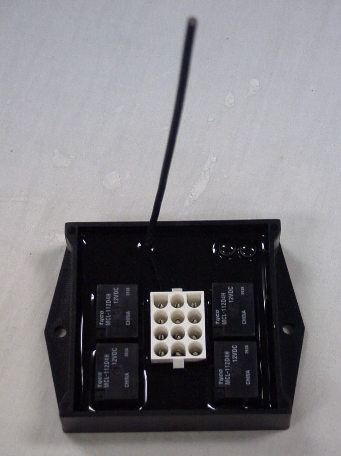
R932039500
May 08, 2007915MHz RECEIVER
Equipment Class
CYY - Communications Receiver used w/Pt 15 Transmitter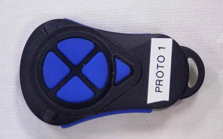
R932039010
May 06, 2007915MHz Transmitter
Equipment Class
DSC - Part 15 Security/Remote Control Transmitter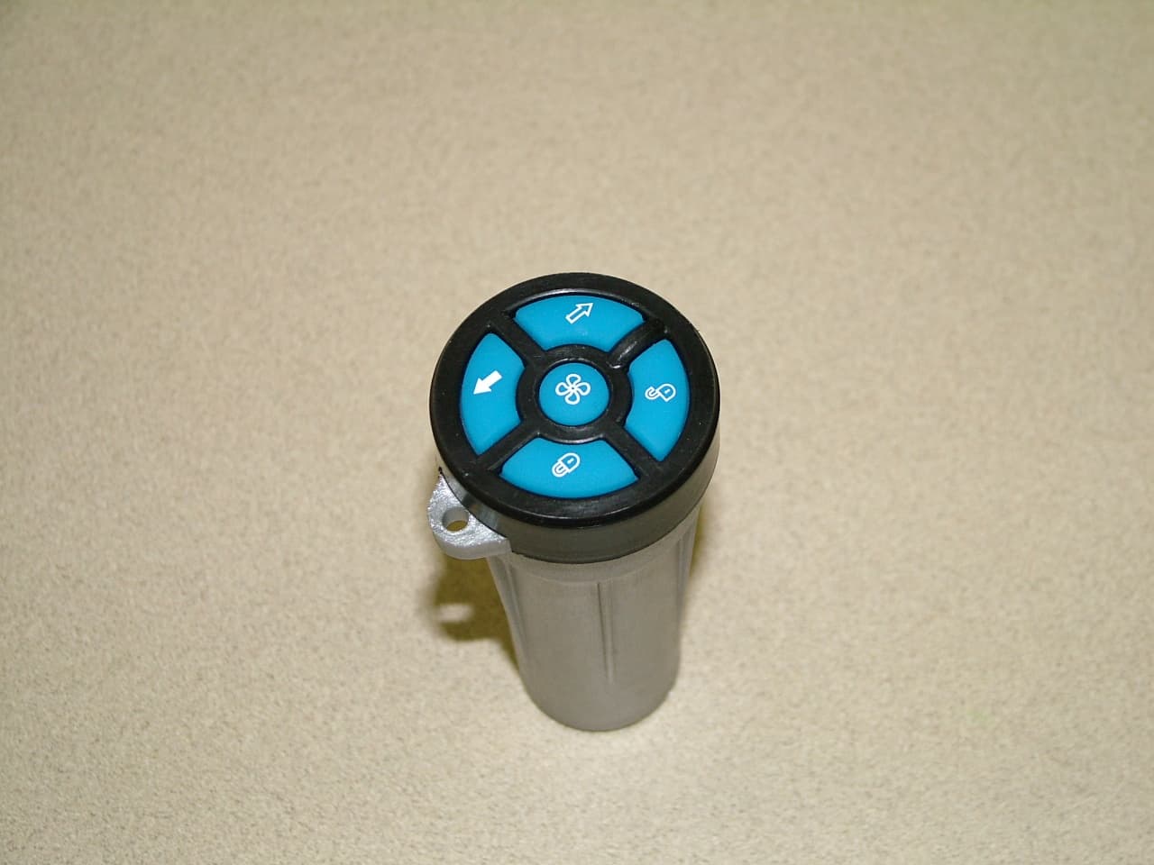
R932033010
Mar 21, 2006KEY CAPTAIN REMOTE LAUNCHING SYSTEM-TRANSMITTER
Equipment Class
DSC - Part 15 Security/Remote Control Transmitter
R932036-010
Nov 28, 2005Hand Held Transmitter
Equipment Class
DSC - Part 15 Security/Remote Control Transmitter