R932060500915 MHz REMOTE CONTROL RECEIVER
Delta Systems INC.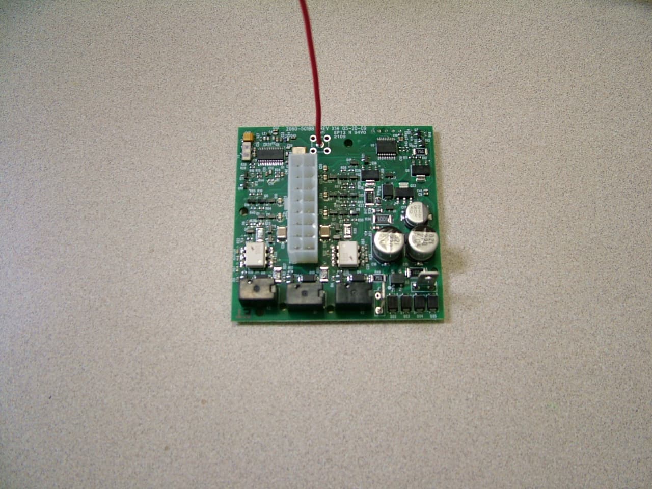
Click to zoom
Application Details
- Equipment Class
- CXX - Communications Rcvr for use w/ licensed Tx and CBs
- Date of Grant
- Jul 23, 2009
- Application Purpose
- Original Equipment
- Date of Application
- Jul 23, 2009
- Equipment Note
- 915 MHz REMOTE CONTROL RECEIVER
- Frequency Range
- 915.00000000 - 915.00000000
- Company
- Delta Systems INC.
- Country
- United States
Documents & Files
Document Text
Text extracted from the exhibit documents filed with the FCC. Open a document above to read the original.
Users Manual
EnclosurE rating: ElEctrical rating: Fcc PEnding NEMA 3, 3R, 12, 13 115/230 VAC, 24 FLA, 60 Hz ic PEnding Etl PEnding Wiring diagraM: Overload protection is not provided. Do not use oversized circuit protection. Use 3/4" conduit only. Grounding between conduit is not automatic – it must be provided upon installation. The control box comes from the factory wired for 115 VAC only. Remove white jumper for 230 VAC operation. Excessively long electrical runs should be wired at 230 VAC. Green or bare wires must only be used for ground. It is unsafe to use a ground as a neutral. Use of the wrong wire size could damage the motors and/or control box. Read the Installation Instructions carefully prior to installation. Read the operating instructions carefully before attempting to use. NOTE: THE MANUFACTURER IS NOT RESPONSIBLE FOR ANY RADIO OR TV INTERFERENCE CAUSED BY UNAUTHORIZED MODIFICATIONS TO THIS EQUIPMENT. SUCH MODIFICATIONS COULD VOID THE USER’S AUTHORITY TO OPERATE THE EQUIPMENT. • The control box should only be installed by a licensed electrician. • caution/aVErtissEMEnt/cuidado: Hazardous voltage will cause severe injury or death. Disconnect from power supply before servicing! • caution/aVErtissEMEnt/cuidado: Risk of electric shock! More than one disconnect switch may be required to de-energize the equipment before servicing! • dangEr/dangEr/PEligro: Hazardous voltage! Ensure that main power is shut off (disconnected) prior to connecting any wires to the terminal blocks! • Non-metallic enclosure does not provide grounding between conduit connections. Use grounding bushings and jumper wires. • The opening of the branch-circuit protective device may be an indication that a fault current has been interrupted. To reduce the risk of fire or electric shock, current-carrying parts and other components of the controller should be examined and replaced if damaged. • Use 30-amp overload protection (refer to all applicable fire, electrical and/or building codes for type of device). • Do not use oversized circuit protection. • Use copper conductors only. ! installation instructions: 1. To raise the lift, press and hold the UP button on the front panel or on the handheld remote. Release the UP button when the lift is at the desired position. 2. To lower the lift, press and hold the DOWN button on the front panel or on the handheld remote. Release the DOWN button when the lift is at the desired position. 3. There is an approximate 3 second delay when switching directions from UP to DOWN or from DOWN to U P. 1. Press and hold the LEVEL switch on the front panel. This will turn Motor #1 off. See wiring diagram. 2. While holding the LEVEL switch down, use the manual UP or DOWN switches to level the boat lift. 3. When the boat lift is level, release the UP or DOWN switch, and then release the LEVEL switch. 1. Press and release the AUTO STOP button on the front panel of the control box to turn this feature on and off. 2. When the AUTO STOP feature is on, press and release the UP or DOWN button on the front panel, or on the remote, to start the boat lift moving. 3. The boat lift will continue to raise or lower until it activates one of the limit switches. In addition, the boat lift will stop when the AUTO STOP button on the front panel or the STOP button on the handheld remote is pressed. 1. Press and release the AUXILIARY button on the front panel or the AUX button on the handheld remote to turn the auxiliary device on for approximately 10 minutes. To turn the auxiliary device off, press and release the AUXILIARY button on the front panel or the AUX button on the handheld remote. 2. Press and hold the AUXILIARY button on the front panel or the AUX button on the handheld remote for three seconds to turn the auxiliary device on indefinitely. To turn the auxiliary device off, press and release the AUXILIARY button on the front panel or the AUX button on the handheld remote. 1. Press and hold the STOP button on the handheld remote. Press and hold the LEARN/CLEAR button on the front panel for three seconds, then release the LEARN/CLEAR button. 2. Continue to press the STOP button on the handheld remote for one more second, then release the STOP button. The handheld remote should now operate the boat lift. 3. Test the handheld remote to ensure proper function. 4. If another handheld remote is accidentally learned to the control box, press and hold the LEARN/CLEAR button on the front cover for ten seconds. To operate the lift, any handheld remotes will have to be reprogrammed to the control box by following Steps 1-4. 5. Spare and replacement handheld remotes can be purchased from your distributor. 1. Remove all four screws from the back of the handheld remote 2. Remove the back plastic cover 3. Remove the battery from the holder 4. Insert one 3-volt, CR2032 battery into the holder. caution/aVErtissEMEnt/cuidado: ENSURE PROPER POLARITY OR THE HANDHELD REMOTE WILL NOT FUNCTION. 5. Re-install the back plastic cover 6. Re-install the four screws. caution/aVErtissEMEnt/cuidado: DO NOT OVER TIGHTEN! Over tightening will strip the holes in the mating plastic cover. raisE and loWEr thE liFt lEVEl thE liFt using thE auto-stoP FEaturE WARNING AVERTISSEMENT/ADVERTENCIA: Prior to use, ensure proper function and position of limit switches. rEPlacing a battEry in thE handhEld rEMotE using thE auxiliary dEVicEs (iF installEd) The auxiliary out provides 5 amps max. at 115 VAC. PrograMMing thE handhEld rEMotE WARNING AVERTISSEMENT/ADVERTENCIA: Ensure that no one else in the vicinity is operating a wireless device. If someone else in the vicinity is operating a wireless device, it could be learned to the control box during this operation. CONTROL BOX FOR A TWO MOTOR BOAT LIFT INSTALLATION INSTRUCTIONS CONTROL BOX FOR A TWO MOTOR BOAT LIFT OPERATING INSTRUCTIONS Control boxes and handheld remotes are proudly manufactured in the USA. N/CN/C GROUNDNEUTRAL INPUT POWER WHITE JUMPER WIRE FOR 115V OPERATION USE COPPER CONDUCTORS ONLY D…
Text truncated - open the document above for the full version.
Block Diagram
Infineon 915 MHz Receiver Chip Wire Antenna Microprocessor Microchip 16F687 Relay Output Up Relay Output Down Relay Output Aux Up Button Input Down Button Input Aux Button Input AutoStop Button Input Learn/Clear Button Input Up Limit Input Down Limit Input 2060-500 Receiver Block Diagram
ID Label/Location Info
Proposed FCC ID and IC Label Proposed Label Location Top Side Delta System FCC ID: R932060500 IC: 6268A-2060500 M/N: 2060-500 S/N: XXXXXX Label Here
Test Report
COMPLIANCE TESTING REPORT PER FCC PART 15 B SUBPART B AND IC RSS-210 Applicant DELTA SYSTEMS INC. Address 10036 AURORA - HUDSON ROAD 1734 FROST ROAD STREETSBORO OH 44241 USA FCC ID R932060500 IC Label 6268A-2060500 Model Number 2060-500 Product Description 915 MHz Remote Control Receiver Date Sample Received 7/2/2009 Date Tested 7/13/2009 Tested By John A. Day Approved By Mario de Aranzeta Report Number 1567AUT9TestReport.pdf Test Results PASS FAIL THE ATTACHED REPORT SHALL NOT BE REPRODUCED EXCEPT IN FULL WITHOUT THE WRITTEN APPROVAL OF TIMCO ENGINEERING, INC. Testing Certificate 0955-01 849 NW State Road 45 Newberry, Fl 32669 USA Phone: 888.472.2424 or 352.472.5500 Fax: 352.472.2030 Email: [email protected] Website: www.timcoengr.com APPLICANT: DELTA SYSTEMS INC. FCC ID: R932060500, IC: 6268A-2060500 REPORT: D\DELTA SYSTEMS\1567AUT9\1567AUT9TestReport.doc Page 2 of 11 TABLE OF CONTENTS REPORT SUMMARY ................................................................................................................. 4 TEST ENVIRONMENT .............................................................................................................. 4 TEST SETUP SUMMARY .......................................................................................................... 4 DUT SPECIFICATION ............................................................................................................... 5 TEST EQUIPMENT LIST ........................................................................................................... 6 TEST PROCEDURES ................................................................................................................ 7 RADIATED SPURIOUS EMISSIONS .......................................................................................... 8 POWER LINE CONDUCTED INTERFERENCE........................................................................... 9 APPLICANT: DELTA SYSTEMS INC. FCC ID: R932060500, IC: 6268A-2060500 REPORT: D\DELTA SYSTEMS\1567AUT9\1567AUT9TestReport.doc Page 3 of 11 ATTESTATIONS This equipment has been tested in accordance with the standards identified in this test report. To the best of my knowledge and belief, these tests were performed using the measurement procedures described in this report. All instrumentation and accessories used to test products for compliance to the indicated standards are calibrated regularly in accordance with ISO 17025 requirements. Testing Certificate # 0955-01 I attest that the necessary measurements were made, under my supervision, at: Timco Engineering Inc. 849 NW State Road 45 Newberry, Fl 32669 Authorized Signatory Name: Mario de Aranzeta Mario de Aranzeta C.E.T. Compliance Engineer/ Lab. Supervisor Date: July 14, 2009 APPLICANT: DELTA SYSTEMS INC. FCC ID: R932060500, IC: 6268A-2060500 REPORT: D\DELTA SYSTEMS\1567AUT9\1567AUT9TestReport.doc Page 4 of 11 REPORT SUMMARY Disclaimer The test results only relate to the item tested. Applicable Rule(s) Pt 15.109, Pt 15.107, ANSI C63.4: 2003, RSS-210, RSS-GEN Related Report No other report TEST ENVIRONMENT Test Facility Timco Engineering, Inc. 849 NW State Road 45 Newberry, FL 32669 USA. Test Condition in the laboratory Temperature: 26ºC Relative humidity: 50% TEST SETUP SUMMARY Test Setup Diagram/ Description The DUT was placed on the turntable per setup per ANSI C63.4: 2003. A test set up photo is provided for clarification. Deviation from the standard/procedure No deviation Modification of DUT No modification APPLICANT: DELTA SYSTEMS INC. FCC ID: R932060500, IC: 6268A-2060500 REPORT: D\DELTA SYSTEMS\1567AUT9\1567AUT9TestReport.doc Page 5 of 11 DUT SPECIFICATION DUT Description 915 MHz REMOTE CONTROL RECEIVER FCC ID FCC ID: R932060500 Model Number 2060-500 IC Cert. IC: 6268A-2060500 Trade Name Delta Systems DUT Power Source 110–120Vac/50– 60Hz DC Power Battery Operated Exclusively Test Item Prototype Pre-Production Production Type of Equipment Fixed Mobile Portable APPLICANT: DELTA SYSTEMS INC. FCC ID: R932060500, IC: 6268A-2060500 REPORT: D\DELTA SYSTEMS\1567AUT9\1567AUT9TestReport.doc Page 6 of 11 TEST EQUIPMENT LIST Device Manufacturer Model Serial Number Cal/Char Date Due Date 3/10-Meter OATS TEI N/A N/A Listed 3/20/07 3/19/10 3-Meter OATS TEI N/A N/A Listed 1/11/09 1/10/12 Antenna: Biconnical Eaton 94455-1 1057 CAL 12/12/07 12/12/09 Antenna: Biconnical Eaton 94455-1 1096 CAL 10/11/08 10/11/10 Antenna: Biconnical Electro- Metrics BIA-25 1171 CAL 4/29/09 4/29/11 Analyzer Blue Tower Quasi- Peak Adapter HP 85650A 2811A01279 CAL 4/13/09 4/13/11 Analyzer Blue Tower RF Preselector HP 85685A 2926A00983 CAL 9/5/07 9/5/09 Analyzer Blue Tower Spectrum Analyzer HP 8568B 2928A04729 2848A18049 CAL 4/13/09 4/13/11 LISN Electro- Metrics ANS-25/2 2604 CAL 10/5/08 10/5/10 LISN Electro- Metrics EM-7820 2682 CAL 4/28/09 4/28/11 Antenna: Log-Periodic Eaton 96005 1243 CAL 12/14/07 12/14/09 APPLICANT: DELTA SYSTEMS INC. FCC ID: R932060500, IC: 6268A-2060500 REPORT: D\DELTA SYSTEMS\1567AUT9\1567AUT9TestReport.doc Page 7 of 11 TEST PROCEDURES Power line conducted Emission: The test procedure used was ANSI C63.4-2003. The spectrum was scanned from 0.15 to 30 MHz. Radiation Interference: The test procedure used was ANSI C63.4-2003 using a spectrum analyzer with a preselector. The bandwidth of the spectrum analyzer was 100 kHz with an appropriate sweep speed. The analyzer was calibrated in dB above a microvolt at the output of the antenna. The video bandwidth was always greater than or equal to the RBW. The frequency was scanned from 30 MHz to 1.0 GHz. When an emission was found, the table was rotated to produce the maximum signal strength. The DUT was measured in three (3) orthogonal planes when necessary. Formula Of Conversion Factors: The field strength at 3m was established by adding the meter reading of the spectrum analyzer (which is set to read in units of dBμV) to the antenna correction factor supplied by the antenna manufacturer plus the coax loss. The antenna correction …
Text truncated - open the document above for the full version.
Contact Information
Applicant
Chop Kramer(RF Enginreer)
Test Firm
Timco Engineering, Inc.Bruno Clavier
Technical Specifications
| # | Rule Parts | Frequency Range | Power Output |
|---|---|---|---|
| 1 | 15B | 915 MHz - 915 MHz | - |
Other Applications from Delta Systems INC.
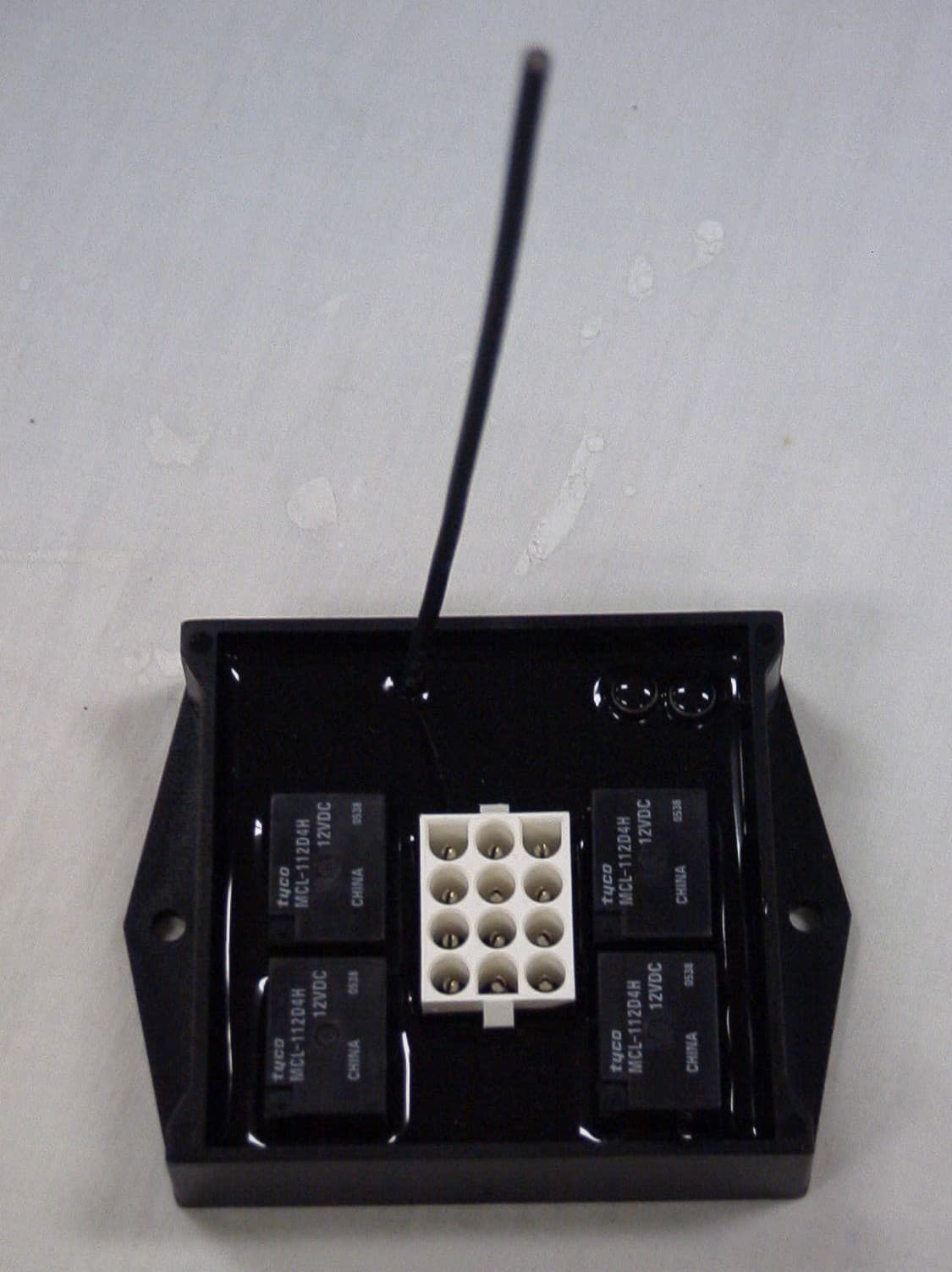
R932039500
May 08, 2007915MHz RECEIVER
Equipment Class
CYY - Communications Receiver used w/Pt 15 Transmitter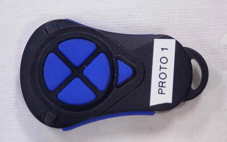
R932039010
May 06, 2007915MHz Transmitter
Equipment Class
DSC - Part 15 Security/Remote Control Transmitter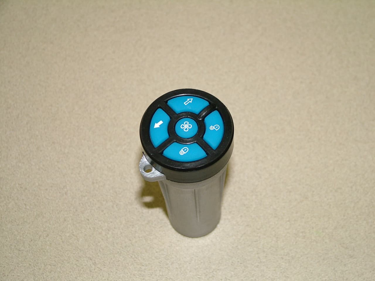
R932033010
Mar 21, 2006KEY CAPTAIN REMOTE LAUNCHING SYSTEM-TRANSMITTER
Equipment Class
DSC - Part 15 Security/Remote Control Transmitter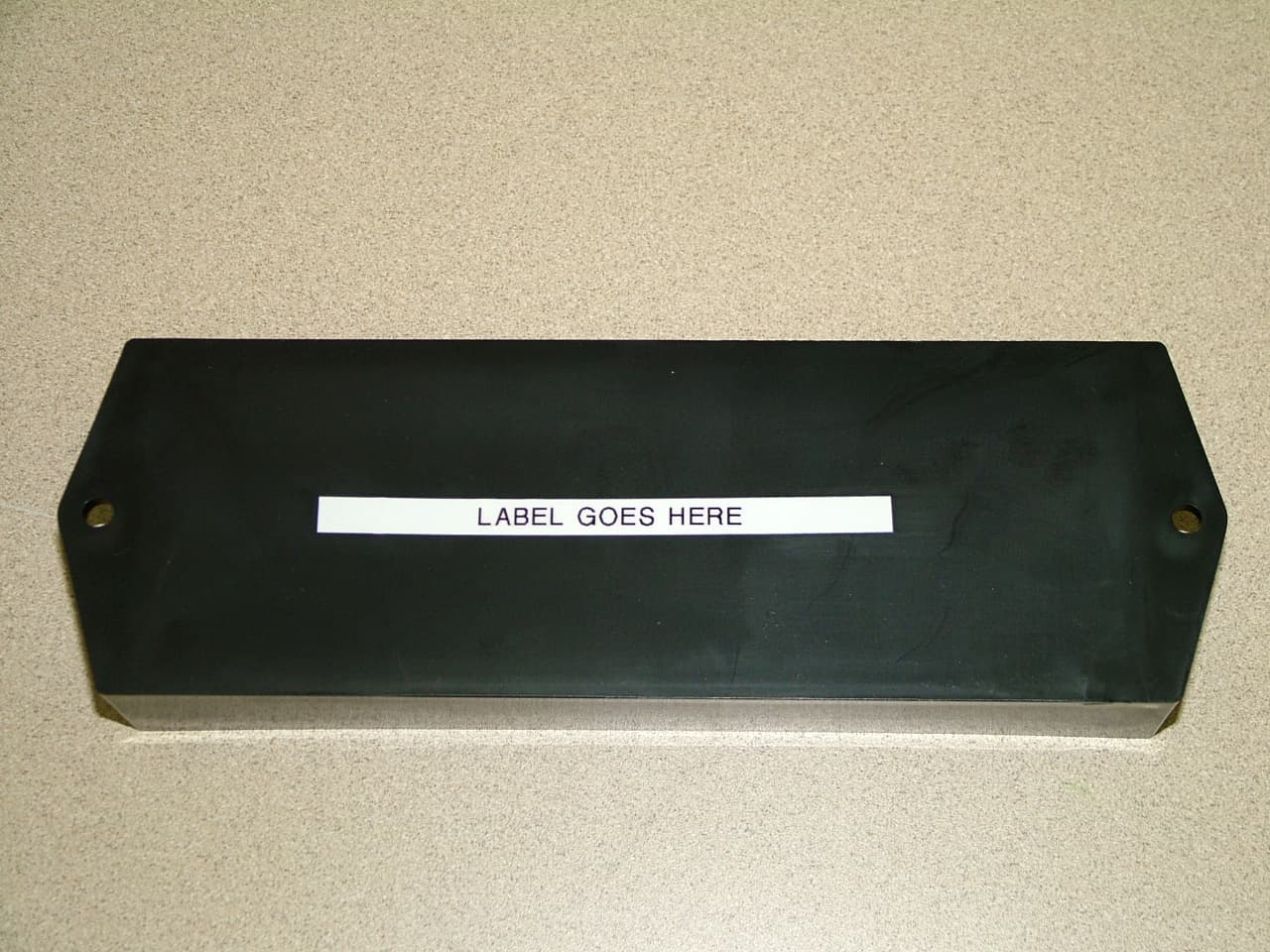
R932033500
Mar 21, 2006KEY CAPTAIN REMOTE LAUNCHING SYSTEM-RECEIVER
Equipment Class
CYY - Communications Receiver used w/Pt 15 Transmitter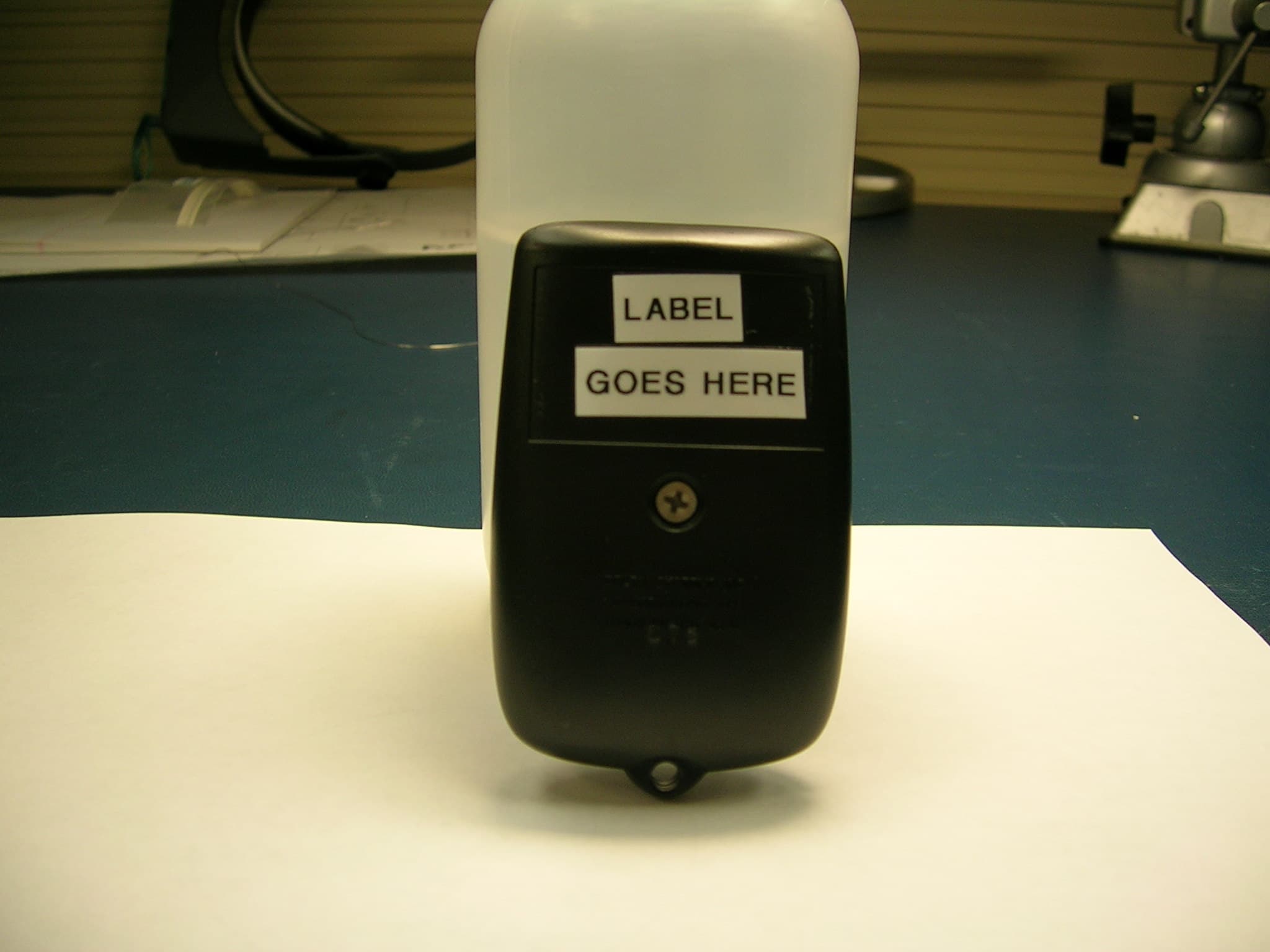
R932036-010
Nov 28, 2005Hand Held Transmitter
Equipment Class
DSC - Part 15 Security/Remote Control Transmitter