RAWLYD208CAWireless Camera
Shenzhen Lian Yi Da Science Co., Ltd.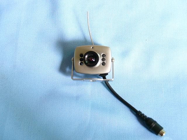
Click to zoom
Application Details
- Equipment Class
- DXX - Part 15 Low Power Communication Device Transmitter
- Date of Grant
- Nov 03, 2003
- Application Purpose
- Original Equipment
- Date of Application
- Nov 03, 2003
- Equipment Note
- Wireless Camera
- Frequency Range
- 2414.20000000 - 2414.20000000
- Country
- China
Documents & Files
Document Text
Text extracted from the exhibit documents filed with the FCC. Open a document above to read the original.
Users Manual
Applicant: Shenzhen Lian Yi Da Science Co., Ltd. FCC ID: RAWLYD208CA MANUAL OF CAMERA Features: Wireless transmission and reception, Small size , Light Weight , Low power consumption, High sensitivity, Easy to Install & operate, Easy to conceal. Operation Instructions: 1. Twist the receiver antenna into the receiver 2. Connect the receiver to the monitor with AV cable; 3. Plug the DC12V 500mA adaptor into the power jack of the receiver; 4. Insert the DC 5V 500mA adaptor into the power jack of the camera; 5. Adjust the frequency controller on the receiver to the required position; 6. Adjust the lens of the camera to best position, Mount the camera with the screw. Function: Suitable for facilities in the supermarket, shop, department Store, clothes shop, workshop, warehouse, school, office and home. Important: The person who uses this product to peep, shoot and undertake Other illegal activities, will be punished. Image pickup device 1/3, 1/4 TV system PLA/CCIR NTSC/EIA Resolution 380 TV lines Scan frequency PLA/CCIR: 50Hz NTSC/EIA: 60Hz Minimum illumination 3LUX Output frequency 2410MHz~2480MHz Power supply DC5V 500mA FCC Information This device complies with part 15 of the FCC Rules, Operation is subject to the following two conditions: (1)This device may not cause harmful interference, and (2) This device must accept any interference received, including interference that may cause undesired operation. CAUTION: Changes or modifications not expressly approved by Summer infant may void the users authority to operate this equipment. NOTE: This equipment has been tested and found to comply with the limits for a Class B digital device, pursuant to part15 of the FCC Rules. These limits are designed to provide reasonable protection against harmful interference in a residential installation. This equipment generates, uses and can radiate radio frequency energy and, if not installed and used in accordance with the instructions, may cause harmful interference to radio communications, However, there is no guarantee that interference will not occur in a particular installation. If this equipment does cause harmful interference to radio or television reception, which can be determined by turning the equipment off and on, the user is encouraged to try to correct the interference by one or more of the following measures: l Reorient or relocate the receiving antenna l Increase the separation between the equipment and the receiver l Consult the dealer or an experienced radio / TV technician for help.
Block Diagram
Applicant: Shenzhen Lian Yi Da Science Co., Ltd. FCC ID: RAWLYD208CA Block Diagram Video Audio Power DC5V 5V Regulatoer CMOS Camera 2410~2480 MHz Modulator RF Power AMP Microphone 5.5MHz Modulator Audio AMP
External Photos
Applicant: Shenzhen Lian Yi Da Science Co., Ltd. FCC ID: RAWLYD208CA (1) EUT top view (2) EUT bottom view
ID Label/Location Info
Applicant: Shenzhen Lian Yi Da Science Co., Ltd. FCC ID: RAWLYD208CA Proposed Label Location on EUT EUT Bottom View/Proposed FCC ID Location FCC ID: RAWLYD208CA
Internal Photos
Applicant: Shenzhen Lian Yi Da Science Co., Ltd. FCC ID: RAWLYD208CA (3) EUT inside whole view (4) Main&RF board component side (5) Main&RF board solder side
Operational Description
Applicant: Shenzhen Lian Yi Da Science Co., Ltd. FCC ID: RAWLYD208CA Operational Decription 208CA wireless transmitter module intended for in 2410~2480MHz wireless A/V signal Sender and Receive set as RF output modulator, which converts the FM video and audio signal into the RF signal for TV or monitor. 1) This circuit modulates the vocie or data onto a carrier frequency using FM. The modulated carrier signal is amplified and feeds to the antenna. 2) The audio signal picked up by the microphone is a very low – signal A microphone amplifier is used to amplify this signal so that it can be transmitted. This device has a outside antenna. And this device can also be seemed as a portable device with the monitor and can use within 30 feet indoor or 120 feet if without obstruction. You can fixed the device on a table or wall by screwed the mounting base. To fix the device, please follow the installation. And please make sure the supervision and monitor are set the same band before in use. Specification for 208CA wireless camera: * Transistors frequency : 2410~2480MHz * Audio modulate: 5.5MHz * Oscillator types: Three capacitance Oscillator * Power supply: DC5V 500mA * Video System: NTSC * Output RF Power: <=10mW * Video Level: 1Vp-p * MaxRange: 120 feet * Transmitter Antenna: Directional * Transmitter Sensitivity: 0dbm FCC * Indoor/Outdoor: Indoor Only * Differential Gain +-8% * Audio Input Impedance 1.0K * Video Input Impedance 1.2K
Schematics
TX2400A-0927.sch-1 - Thu Oct 16 11:11:03 2003 PDF created with FinePrint pdfFactory trial version http://www.fineprint.com
Test Report
The test report consists 24 pages in total. It may be duplicated completely for legal use with the allowance of the applicant. It shall not be reproduced except in full, without the written approval of Ke Mei Ou Laboratory Corporation. The test result in the report only applied to the tested sample. FCC TEST REPORT Under : FCC 15 Subpart C, Paragraph 15.249: 2002 Prepared For : Shenzhen Lian Yi Da Science Co., Ltd. #2009A, Saige Building, Huaqiang Road North, Shenzhne China October 15, 2003 FCC ID: RAWLYD208CA EUT: Wireless Camera Model: LYD208CA Report Type: Original Report Test Engineer: Peter Lin Test Date: September 28, 2003 Review By: Apollo Liu / Manager FEDERAL COMMUNICATIONS COMMISSION Registration Number: 125782 Ke Mei Ou Laboratory Co., Ltd. 7A, Jiaxiangge, Jiahuixincheng, No.3027, Shennan Rd., Futian, Shenzhen, Guangdong, P.R.China. Zip Code: 518033 Tel: + 86 755 83642690 Fax: + 86 755 83297077 www.kmolab.com Shenzhen Lian Yi Da Science Co., Ltd. FCC ID: RAWLYD208CA FCC ID Report Report #: KSZ2003091802J Page 2 of 2 TABLE OF CONTENTS 1. General Information...........................................................................................................................................................3 1. 1 Notes...............................................................................................................................................................................3 1. 2 Testing Laboratory..........................................................................................................................................................3 1. 3 Details of Applicant........................................................................................................................................................3 1. 4 Application Details.........................................................................................................................................................3 1. 5 Test Item.........................................................................................................................................................................3 1. 6 Test Standards.................................................................................................................................................................4 2. Technical Test.......................................................................................................................................................................5 2. 1 Summary of Test Results................................................................................................................................................5 3. EUT Modifications..............................................................................................................................................................6 4. Conducted Power Line Test................................................................................................................................................7 4. 1 Test Equipment...............................................................................................................................................................7 4. 2 Test Procedure................................................................................................................................................................7 4. 3 Test Setup.......................................................................................................................................................................7 4. 4 Configuration of the EUT...............................................................................................................................................8 4. 5 EUT Operating Condition...............................................................................................................................................9 4. 6 Conducted Power Line Emission Limits........................................................................................................................9 4. 7 Conducted Power Line Test Result...............................................................................................................................10 5. Radiated Emission Test.....................................................................................................................................................12 5. 1 Test Equipment.............................................................................................................................................................12 5. 2 Test Procedure..............................................................................................................................................................12 5. 3 Radiated Test Setup......................................................................................................................................................12 5. 4 Configuration of the EUT.............................................................................................................................................13 5. 5 EUT Operating Condition.............................................................................................................................................13 5. 6 Radiated Emission Limit..............................................................................................................................................13 5. 7 Radiated Emission Test Result......................................................................................................................................14 6. Band Edge..........................................................................................................................................................................16 6. 1 Test Equipment...............................................................................................................................…
Text truncated - open the document above for the full version.
Test Setup Photos
Applicant: Shenzhen Lian Yi Da Science Co., Ltd. FCC ID: RAWLYD208CA Conducted emission test view Radiated emission test view
Contact Information
Applicant
Mingsheng Deng(Manager)
Test Firm
Ke Mei Ou Laboratory Co., Ltd.Apollo Liu
Technical Specifications
| # | Rule Parts | Frequency Range | Power Output |
|---|---|---|---|
| 1 | 15C | 2.41 GHz - 2.41 GHz | - |
Other Applications from Shenzhen Lian Yi Da Science Co., Ltd.
RAWLYD240CA
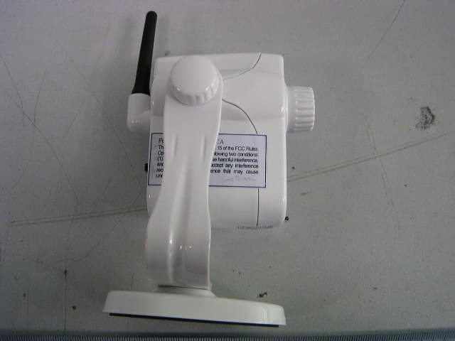
Apr 07, 2007Wireless Camera
Equipment Class
DXX - Part 15 Low Power Communication Device Transmitter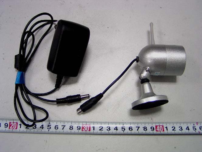
RAWLYD801CA
Jan 07, 2007Wireless Camera
Equipment Class
DXX - Part 15 Low Power Communication Device Transmitter
RAWLYD802CWAS
Dec 06, 2005Wireless Camera
Equipment Class
DXX - Part 15 Low Power Communication Device Transmitter
RAWLYD2G4CWAS
Nov 02, 2005Wireless Camera
Equipment Class
DXX - Part 15 Low Power Communication Device Transmitter
RAWLYD203CA
Aug 03, 2003Wireless Camera
Equipment Class
DXX - Part 15 Low Power Communication Device Transmitter