RAWLYD802CWASWireless Camera
Shenzhen Lian Yi Da Science Co., Ltd.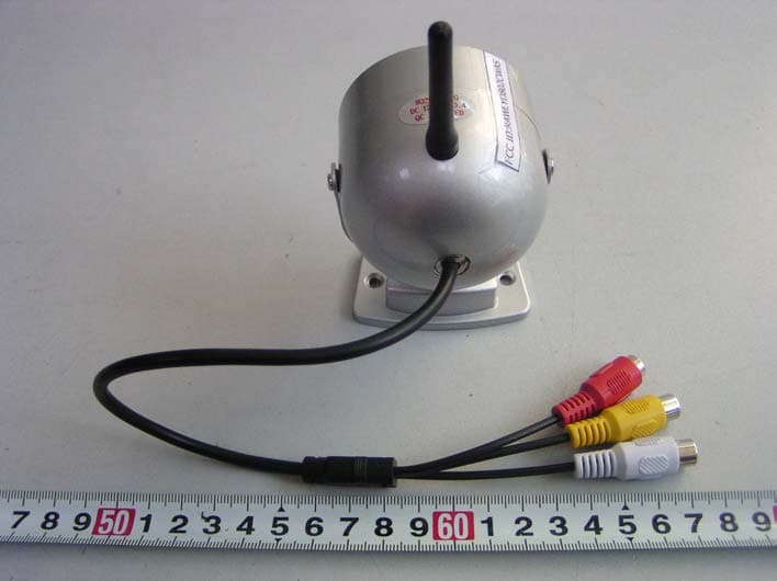
Click to zoom
Application Details
- Equipment Class
- DXX - Part 15 Low Power Communication Device Transmitter
- Date of Grant
- Dec 06, 2005
- Application Purpose
- Original Equipment
- Date of Application
- Dec 06, 2005
- Equipment Note
- Wireless Camera
- Frequency Range
- 2414.00000000 - 2468.00000000
- Country
- China
Documents & Files
Document Text
Text extracted from the exhibit documents filed with the FCC. Open a document above to read the original.
Users Manual
802CA wireless transmitter user’s manual Thanks for your choosing this wireless camera, in order to have a good use of this product, please read this manual carefully. Specification Parameters: Image device: 1/3” CMOS TV system: PAL/CCIR NTSC/EIA Valid pixel: PAL: 628×582 NTSC: 510×492 Image area: PAL: 5.78×4.19mm NTSC: 4.69×3.45mm Horizontal definition: 320Line Scanning frequency: PAL/CCIR: 50Hz NTSC/EIA: 60Hz Minimum illumination: 3LUX Sensitivity: 18 dB/AGC OFF Output power: 70dBμV/m(3m) Output frequency: 2.414GHz 2.432GHz 2.450GHz 2.468GHz Frequency control: PLL, with high sensitivity. Transmitting signal: Video Audio Open distance: 20 30M IR night vision distance: 15 18M Rating voltage: DC+12V Rating current: 500mA Power consumption: ≤ 640mW Working temperature: -10 +50 Working environment: Indoor or outdoor avoid from rain Size: 56x60x45 mm Weight: 185g Illustration: Operation instruction: 1.Fix the camera to the direction you want to monitor; 2.Insert the DC+12V/500mA power adapter into the alternating current socket,connect the Optical lens antenna IR LED DC input Video output power adapter plug to the camera to have it power on; 3.Keep the distance of each camera beyond 2 meters if more than 2pcs of cameras are mounted; keep the distance between the camera and the receiver beyond 2 meters, otherwise they will interfere each other and cause a poor picture. 4.Mount the 2.4G antenna to the receiver; 5.Connect the video/audio interface of the receiver to the TV or monitor with AV cord; 6.Insert the DC+12V/500mA power adapter to the alternating current socket, conect the DC power adapter to the receiver to have it power on; 7.Select the frequency channel switch to keep the receiver and the camera with the same frequencies; 8.You can see the pictures and hear the voice through TV, adjust the location of the camera to have a efficacious surveillance. 9.If you don’t want to use the receiver, you can connect the AV cord of the camera directly to the video/audio interface of TV or monitor to display the picture. Trouble shooting guide 1.No signals on TV or monitor Please check if the power adapter of the camera is well connected with the alternating current socket, if the alternating current is power on, or if power adapter of the camera is well inserted into the power input jack of the receiver; 2.Can’t pick up the picture or the picture is not clear: Please check if the camera is power on; or if the camera is too far away from the receiver(open distance is 500 800m); or if there are some electromagnetism barrier between the camera and the receiver(for example the steel building); or if the camera and the receiver are on the same channel( be attention that two cameras with the same transmitting frequency can not work synchronously in valid distance, otherwise they will interfere each other); make sure that the antenna is well mounted on the receiver. Keep the antenna of the receiver far away from copper&iron electromagnetism barriers, Powerful same frequency transmitter or or radio station will cause interfere to the receiver. Accessories: Antenna 1piece AV cord 1piece DC12V/500mA power adapter 1piece Manual 1piece Warranty card 1piece Receiver 1piece optional Caution: Changes or modifications to this unit not expressly approved by the party responsible for compliance will void the user’s authority to operate the equipment. Any change to the equipment will void FCC grant. NOTE: This equipment has been tested and found to comply with the limits for a digital device, pursuant to part 15 of the FCC Rules. These limits are designed to provide reasonable protection against harmful interference in a residential installation. This equipment generates, uses and can radiate radio frequency energy and, if not installed and used in accordance with the instructions, may cause harmful interference to radio communications. However, there is no guarantee that interference will not occur in a particular installation. If this equipment does cause harmful interference to radio or television reception, which can be determined by turning the equipment off and on, the user is encouraged to try to correct the interference by one or more of the following measures: --Reorient or relocate the receiving antenna. --Increase the separation between the equipment and receiver. --Connect the equipment into an outlet on a circuit different from that to which the receiver is connected. --Consult the dealer or an experienced radio/TV technician for help. This device complies with Part 15 of the FCC Rules. Operation is subject to the following two conditions: (1) this device may not cause harmful interference, and (2) this device must accept any interference received, including interference that may cause undesired operation.
External Photos
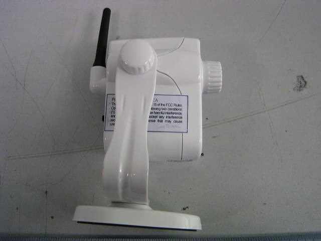
External Photos EUT-Front View EUT-Back View
ID Label/Location Info
ID Label Label
ID Label/Location Info
ID Label/Location Label Location Information Specifications: Text is Black or white in color and is left justified. Labels are printed in indelible ink on permanent adhesive backing or silk-screened onto the EUT or shall be affixed at a conspicuous location on the EUT. Label Location
Internal Photos
Internal Photos EUT-Inside View (1) EUT-Inside View (2) EUT-Inside View (3) EUT-Inside View (4) EUT-Inside View (5) EUT- LED PCB Front view EUT- LED PCB Back view EUT- Main PCB Front View EUT- Main PCB Back View EUT- RF PCB Front View EUT- RF PCB Back View
Operational Description
Operational Description 802CA wireless transmitter module intended for in 2414~2468MHz wireless A/V signal Sender and Receive set as RF output modulator, which converts the FM video and audio signal into the RF signal for TV or monitor. This device has a outside antenna. You can fixed the device on a table or wall by screwed the mounting base. To fix the device, please follow the installation. And please make sure the supervision and monitor are set the same band before in use.
Operational Description
Specification for 802CA wireless camera * Transistors frequency CH1:2414MHz,CH2:2432MHz,CH3:2450MHz,CH4:2468MHz * Audio modulate: 6.0MHz *Modulation: FM *Turn up procedure: phase locking loop *Microphone Frequency range: 20~20,000Hz *Antenna Specification: 36mm+ 1mm * Power supply: DC12V 500mA * Video System: PAL/NTSC * Output RF Power: 70dBμV/m(3m) * Video Level: 1Vp-p * Transmitter Antenna: Directional * Indoor/Outdoor: Indoor Only * Audio Input Impedance 1.0K * Video Input Impedance 1.2K
Schematics
802DB-20050527.SCH-1 - Tue Nov 08 10:07:35 2005
Schematics
802C-050531.sch-1 - Tue Nov 08 09:02:14 2005
Schematics
TX2401B-20050219.sch-1 - Mon Oct 10 20:30:50 2005
Test Report
Note: The test report is specially limited to the above company and this particular sample only. It may not be duplicated without prior written consent of Bay Area Compliance Lab Corp. (ShenZhen). This report must not be used by the client to claim product certification, approval, or endorsement by NVLAP, NIST or any agency of the US Government. FCC PART 15.249 EMI MEASUREMENT AND TEST REPORT For Shenzhen Lian Yi Da Science Co., Ltd. #2009A, Saige Building, HuaQiang Road North Shenzhen,China FCC ID: RAWLYD802CWAS November 21, 2005 This Report Concerns: Original Report Equipment Type: Transmitter, Wireless Camera Test Engineer: Louise Lu and Lisa Zhu Report No.: RSZ05111401 Test Date: November 16-17, 2005 Reviewed By: Chris Zeng Prepared By: Bay Area Compliance Lab Corp. (ShenZhen) 6/F, the 3rd Phase of WanLi Industrial Building, ShiHua Road, FuTian Free Trade Zone, ShenZhen, Guangdong 518038, P.R.China Tel: +86-755-33320018 Fax: +86-755-33320008 Shenzhen Lian Yi Da Science Co., Ltd. FCC ID: RAWLYD802CWAS Report # RSZ05111401 Page 2 of 22 FCC PART 15.249 Report TABLE OF CONTENTS GENERAL INFORMATION.......................................................................................................................................3 PRODUCT DESCRIPTION FOR EQUIPMENT UNDER TEST (EUT) ....................................................................................3 OBJECTIVE...................................................................................................................................................................3 RELATED SUBMITTAL(S)/GRANT(S).............................................................................................................................3 TEST METHODOLOGY..................................................................................................................................................3 TEST FACILITY.............................................................................................................................................................3 EXTERNAL I/O CABLE.................................................................................................................................................4 SYSTEM TEST CONFIGURATION ..........................................................................................................................5 JUSTIFICATION.............................................................................................................................................................5 EQUIPMENT MODIFICATIONS.......................................................................................................................................5 CONFIGURATION OF TEST SETUP.................................................................................................................................6 BLOCK DIAGRAM OF TEST SETUP................................................................................................................................6 SUMMARY OF TEST RESULTS...............................................................................................................................7 §15.203 - ANTENNA APPLICATION ........................................................................................................................8 STANDARD APPLICABLE..............................................................................................................................................8 §15.207 - CONDUCTED EMISSION ..........................................................................................................................9 MEASUREMENT UNCERTAINTY....................................................................................................................................9 EUT SETUP..................................................................................................................................................................9 EMI TEST RECEIVER SETUP......................................................................................................................................10 TEST EQUIPMENT LIST AND DETAILS.........................................................................................................................10 TEST PROCEDURE......................................................................................................................................................10 TEST RESULTS SUMMARY..........................................................................................................................................10 TEST DATA................................................................................................................................................................11 PLOT(S) OF TEST DATA..............................................................................................................................................11 §15.205 §15.209(A) §15.249(A) - RADIATED EMISSION ......................................................................................14 M EASUREMENT U NCERTAINTY ..................................................................................................................................14 EUT S ETUP ................................................................................................................................................................14 EMI TEST RECEIVER SETUP......................................................................................................................................15 TEST EQUIPMENT LIST AND DETAILS.........................................................................................................................15 TEST PROCEDURE......................................................................................................................................................15 CORRECTED AMPLITUDE & MARGIN CALCULATION............................................................…
Text truncated - open the document above for the full version.
Test Setup Photos
Test Setup Photos Conducted Emission-Front View Conducted Emission-Side View Radiated Emissions-Front View (above 1GHz) Radiated Emissions-Rear View (above 1GHz) Radiated Emissions-Front View (below 1GHz) Radiated Emissions-Rear View (below 1GHz)
Contact Information
Applicant
Mingsheng Deng(Manager)
Test Firm
Bay Area Compliance Laboratory Corp. (Shenzhen)John Chan
Technical Specifications
| # | Rule Parts | Frequency Range | Power Output |
|---|---|---|---|
| 1 | 15C | 2.41 GHz - 2.47 GHz | - |
Other Applications from Shenzhen Lian Yi Da Science Co., Ltd.
RAWLYD240CA
Apr 07, 2007Wireless Camera
Equipment Class
DXX - Part 15 Low Power Communication Device Transmitter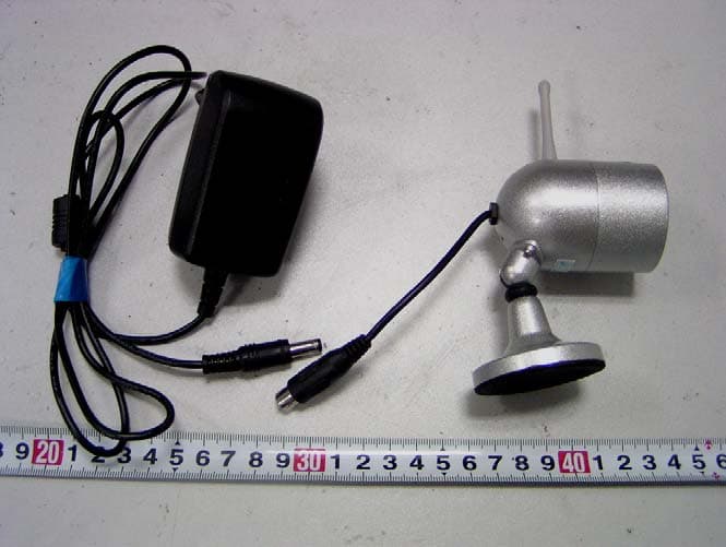
RAWLYD801CA
Jan 07, 2007Wireless Camera
Equipment Class
DXX - Part 15 Low Power Communication Device Transmitter
RAWLYD2G4CWAS
Nov 02, 2005Wireless Camera
Equipment Class
DXX - Part 15 Low Power Communication Device Transmitter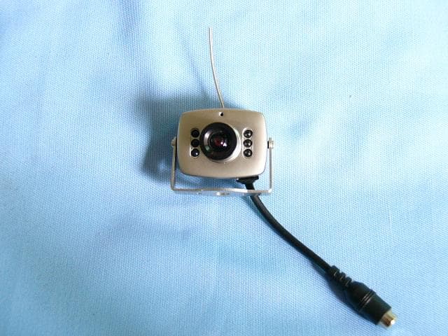
RAWLYD208CA
Nov 03, 2003Wireless Camera
Equipment Class
DXX - Part 15 Low Power Communication Device Transmitter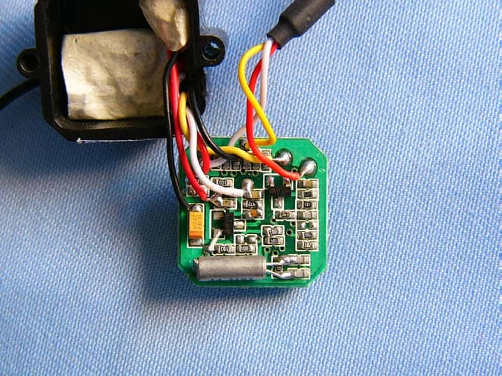
RAWLYD203CA
Aug 03, 2003Wireless Camera
Equipment Class
DXX - Part 15 Low Power Communication Device Transmitter