RAWLYD240CAWireless Camera
Shenzhen Lian Yi Da Science Co., Ltd.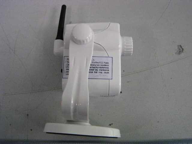
Click to zoom
Application Details
- Equipment Class
- DXX - Part 15 Low Power Communication Device Transmitter
- Date of Grant
- Apr 07, 2007
- Application Purpose
- Original Equipment
- Date of Application
- Apr 07, 2007
- Equipment Note
- Wireless Camera
- Frequency Range
- 2414.00000000 - 2468.00000000
- Country
- China
Documents & Files
Document Text
Text extracted from the exhibit documents filed with the FCC. Open a document above to read the original.
Users Manual
User’s manual for CM240C Wireless Camera Thank you for choosing this kind of product. Please read this manual carefully before you use this product, which can help you to use it better. 1. Introduction CM240C wireless camera use ISM wave frequency, 2414~2468MHz, to transit audio and video signals. It contains a lithium battery, which can last 3,5hours, external power is not necessary. It can be used for baby monitoring, nursing home care, security, surveillance ect. 2. Specification a. Image device: 1/3 color CMOS b. System: PAL/NTSC c. Validity pixel: NTSC: 510 x 490 PAL:628 x 586 d. Image size: 9.2um x 7.2um e. ISM Frequency: 2414~2468MHz f. Channel Frequency: Ch1=2414MHz Ch2=2468MHz g. Audio Frequency: 6.0MHz h. Unobstructed transmission distance: 100meter i. Power adapter: lithium battery: 3.7V external power: DC5V/500mA j. Normal current: 130mA Maximum current: 350mA(when charged) k. Maximum working-last time: 3.5 hours l. Adjustable lens 3. Installment a. You can install this CM240C in a fixed location to observe a stationary place or some other places such as an office, a baby bed ect. b. In order to have a clear image, you can assemble this device in a place with sound illumination. c. Please install this product in a spacious place, in which this device can transmit farther. Do not install this product in a place near big metal or a place having some obstacles between the transmitter and the receiver, which can influence the transmission distance. The installment place must be far from high temperature. Do not use this device close to fire or extremely wet place. 4. Operation guide a. When you use this product the first time, please put the plug of power adapter (DC5/500mA) into the AC socket. Put the DC wire in the socket of (5V DC IN) at the back of the product to charge. When the red light is on, it means it is charging. When the green light is on, it means the charge is finished. b. If the battery power is used up, it will take 3 hours to recharge it. c. The switch at the location of (off) means power off, CH1means channel one (2414MHz), CH2 means channel 2(2468MHz). d. If the picture is not clear, you can adjust the lens to get a nice picture. e. If you want to observe the scenery of different angle, you can keep the camera bracket stationary and rotate the camera body up and down. f. You can insert the power adapter when the camera is power on, which will shift to be powered by power adapter and save the energy of the battery. 5. Usage guide a. What should be done when the image is not clear or the color is not normal? b. Please recharge your camera battery timely. c. B. What should be done when the image is not steady or can not receive signal? d. Please check whether the camera or the receiver has been connected with power. e. Please check whether the camera is too far away from the receiver or there is magnetic obstacle between them (such as steel construction may be serious obstacle to the transmission signal). f. Please check whether the transmission frequency has matched with the receiving frequency (notice that there should not be two cameras with same frequency working at the same time in a limited distance, or they will interference each other and cause not clear picture. g. The antenna of the camera or the receiver must be far from magnetic obstacle such as steel, copper etc. h. The transmission of the same frequency with enormous power or the work of car-loading radio station may interference the receiver. 6. Accessories and data • DC5V/500mA power adapter one • Manual one • Paper of free repair guarantee one FCC Warning: This device complies with part 15 of the FCC Rules. Operation is subject to the following two conditions: 1) This device may not cause harmful interference, and 2) This device must accept any interference received, including interference that may cause undesired operation. This equipment has been tested and found to comply with the limits for a Class B digital device, pursuant to part 15 of the FCC Rules. These limits are designed to provide reasonable protection against harmful interference in a residential installation. This equipment generates, uses and can radiate radio frequency energy and, if not installed and used in accordance with the instructions, may cause harmful interference to radio communications. However, there is no guarantee that interference will not occur in a particular installation. If this equipment does cause harmful interference to radio or television reception, which can be determined by turning the equipment off and on, the user is encouraged to try to correct the interference by one or more of the following measures: --Reorient or relocate the receiving antenna. --Increase the separation between the equipment and receiver. --Connect the equipment into an outlet on a circuit different from that to which the receiver is connected. --Consult the dealer or an experienced radio/TV technician for help. The equipment compliance with FCC radiation exposure limit set forth for uncontrolled Environment. Changes or modifications to this unit not expressly approved by the party responsible for compliance will void the user’s authority to operate the equipment. Any change to the equipment will void FCC grant.
Cover Letter(s)
Shenzhen LianYi Da Science Co.,Ltd. FCC Confidential Authorization December 21, 2006 FEDERAL COMMUNICATIONS COMMISSIONS Authorization and Evaluation Division 7435 Oakland Mills Road Columbia, MD 21046 Confidentiality Request regarding application for certification of FCC ID: ( RAWLYD240CA ) . Pursuant to Sections 0.457 and 0.459 of the Commission’s Rules, we hereby request long-term confidential treatment of information accompanying this application as outlined below: BOM, Circuit Description The above materials contain trade secrets and proprietary information not customarily released to the public. The public disclosure of these materials may be harmful to the applicant and provide unjustified benefits to its competitors. The applicant understands that pursuant to Section 0.457 of the Rules, disclosure of this application and all accompanying documentation will not be made before the date of the Grant for this application. Sincerely Yours, Signature: Mingsheng Deng Manager Shenzhen LianYi Da Science Co.,Ltd. Form 05
External Photos
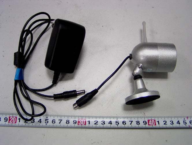
External Photos EUT- Front View EUT- Rear View EUT- Left Side View EUT- Right Side View
ID Label/Location Info
FCC ID Label/Location FCC ID Label Label Location Information Specifications: Text is Black or white in color and is left justified. Labels are printed in indelible ink on permanent adhesive backing or silk-screened onto the EUT or shall be affixed at a conspicuous location on the EUT. Refer to the below arrow. FCC ID: RAWLYD240CA This device complies with part 15 of the FCC Rules. Operation is subject to the following two conditions: (1) This device may not cause harmful interference, and (2) this device must accept any interference received, including interference that may cause undesired operation.
Internal Photos
Internal Photos EUT- Inside View (1) EUT- Inside View (2) EUT- Main board Top View EUT- Main board Bottom View EUT-RF board Top View EUT-RF board Bottom View (1) EUT-RF board Bottom View (2) Battery View
Schematics
1-1 SHENZHEN LIANYIDA SCIENCE CO; LTD DESIGNER PRODUCT NUMBER ACCESSORY ASSEMBLE DATE SIGNATORY NUMBER PLACE MARK NO COLOR MATERIAL ACCESSORY NAME 1:1 WEIGHT PAGE RATE APPROVED EXAMINER NUMBER 240CWAS 电路原理图(B板) TX MODULE 1 VDD 2 TS 3 STAT 4 GND 5 CC 6 FB/CE 7 CS 8 BATT U10 RT9501BPF D1 SS14 1 2 3 Q1 APM2070PD R1 500mR R13 1K R14 7.5K R15 30K C31uF C41uF D2 SS14 C60.1uF R7 10K R8 10K R9 10K D6 SS14 1234 56789 10 SW1 132 J1 DC_MINI_JACK L1 22uH D3 SS14 R23 100K R24 300K C10.1uF + C9 220uF/10V + C10 100uF/10V C20.1uF 123456789 101112 J3 CON2.0X12MM-2 123456 J2 2 1 3 Q22N3904 L2 150uH 123 J4 CON3PIN1.25MM-DIP + C5 100uF/10V C110.1uF C140.1uF C161nF 2 1 3 Q3 2N3906 R19 10K R20 1K R2 100K + C17 100uF/10V L4 150uH R3 NC R4NC R5 10K C7 0.1uF 1 T1 1 VO1 2 GND 3 VIN 4 EN 5 VO2 U3 RT9701PB 1 COMP 2 FB 3 EN 4 GND 5 LX 6 VIN 7 FREQ 8 SS U1 RT9270PF C80.1uF C13 56pF C15 1nF R6 0R R10 NC R11 22K + C18 100uF/10V C121uF R12 NC R16 1R R17 0R R18 NC C19 NC VR1 F1 2A ZD1 PTZ5.6B BAT_SW AUDIO CMOS_VIDEO CH_LED_G CH_LED_R CH_LED_G CH_LED_R AUDIO TX_VIDEO CH_SEL1 TX_+5V CH_SEL1 BAT_SW V_BAT TX_+5V V_BAT V_BAT AUDIO V_BAT TX_VIDEO CMOS_VIDEO V_BAT CH_SEL2 CH_SEL2 11 22 33 44 D D C C B B A A 11 RW67Tx-APN-001 RW67 Tx -A PN-00 1 1. 1 *E: \Prod ucts -Data\ Pro du cts-D ata(20 07)\ Camera\2 40 C\ CM2 40 C\ CM2 40 C\ LYD Tx -0 70 320 .SCH Ti tl eSize: No: Dat e:File: Revision:Sheet of A4 Cann ot open fil e E: \D ocument s an d Sett in gs\ cheng chi a\ My 20 07 -03-2 0 10 KR20 47 0n F C21 10 0n F C24 33 pFC23 8MHzY1 33 pFC22 SPI_SE 10 KR30 10 K R33 10 K R34 10 K R35 CH0 CH1 CH2 D_ 3.3 V 4. 7uFC25 3. 3V 1u FC39 3. 3V VT 5. 6PR40 82 KC50 20 KR9 75 0R2710 uF C35 51 K R17 1u FC14 10 0K R32 2. 2nFC31 20 K R8 39 0R26 0RR4 2. 2uFC16 1u FC12 1. 2K R14 75 RR13 4. 7uFC19 10 KR19 75 RR16 20 KR10 0RR5 1. 2KR15 68 p C11 VT Vi deo 10 0KR22 15 nFC20 11 0RR21 1u FC13 4. 7uF C18 3. 3V 3. 3V 2. 7nHL3 4. 7nHL2 1p FC2 10 pFC1 39R2 8. 2nHL1 10 pFC3 3. 3V AL VCOV DD 1 VT 2 GN D 3 CP 4 AV T2 5 ACP2 6 AO UT2 7 AV DD2 8 AO UT 1 9 NC 10 AV T1 11 ACP1 12 AV DD 1 13 VD D 14 SPI_SE 15 BCR 16 REG1 D8 17 PD_REG1D8 18 XT AL1 19 XT AL2 20 VD D33 21 SPICLK/CS0 22 SPILE/ CS1 23 SPIDATA/CS2 24 BX 25 SYNVSS 26 RFGND2 27 PAOUT2 28 PAOUT1 29 RFGND1 30 PAVDD 31 NC 32 RTC6701U1 47 nFC96 10 pFC8 Comment: 47 nFC97 47 nF C98 10 pFC7 RFOUT 6M 5.0 V Mo de U2-- >NP R25- ->NP 3.3V Mo de Power Mode 1 3 2 LF2 012 -B2R4FAA F1 10 K R36 18 pF C51 LYD-17mm-TX JU MPR100 3.3V Mode AN T Frequ ency rang e:2 410 ~248 0MHz
Test Report
Note: This test report is for the customer shown above and their specific product only. It may not be duplicated or used in part without prior written consent from Bay Area Compliance Laboratory Corp. (Shenzhen). This report must not be used by the customer to claim product certification, approval, or endorsement by NVLAP, NIST, or any agency of the Federal Government. FCC PART 15.249 EMI MEASUREMENT AND TEST REPORT For Shenzhen Lian Yi Da Science Co., Ltd. F5, A Building of Cunnan Industrial Estate, Shuidou 2Road, Shuidou, Yousong, Longhua Town, Bao'an District, Shenzhen, China FCC ID: RAWLYD240CA This Report Concerns: Original Report Equipment Type: Wireless camera Test Engineer: Charmi Peng Report No.: RSZ06111304 Test Date: 2007-01-02 to 2007-01-03 Report Date: 2007-04-05 Reviewed By: EMC Manager: Boni Baniqued Prepared By: Bay Area Compliance Laboratory Corp. (Shenzhen) 6/F, the 3rd Phase of WanLi Industrial Building, ShiHua Road, FuTian Free Trade Zone Shenzhen, Guangdong, China. Tel: +86-755-33320018 Fax: +86-755-33320008 Shenzhen Lian Yi Da Science Co., Ltd. FCC ID: RAWLYD240CA Report #: RSZ06111304 Page 2 of 19 FCC PART 15.249 Report TABLE OF CONTENTS GENERAL INFORMATION.......................................................................................................................................3 PRODUCT DESCRIPTION FOR EQUIPMENT UNDER TEST (EUT) .....................................................................................3 OBJECTIVE...................................................................................................................................................................3 RELATED SUBMITTAL(S)/GRANT(S).............................................................................................................................3 TEST METHODOLOGY..................................................................................................................................................3 TEST FACILITY.............................................................................................................................................................4 EXTERNAL I/O CABLE..................................................................................................................................................4 SYSTEM TEST CONFIGURATION ..........................................................................................................................5 JUSTIFICATION.............................................................................................................................................................5 EQUIPMENT MODIFICATIONS.......................................................................................................................................5 CONFIGURATION OF TEST SETUP.................................................................................................................................5 BLOCK DIAGRAM OF TEST SETUP................................................................................................................................5 SUMMARY OF TEST RESULTS ...............................................................................................................................6 §15.203 - ANTENNA REQUIREMENT......................................................................................................................7 STANDARD APPLICABLE..............................................................................................................................................7 ANTENNA CONNECTOR CONSTRUCTION......................................................................................................................7 §15.207 - CONDUCTED EMISSIONS ........................................................................................................................8 MEASUREMENT UNCERTAINTY....................................................................................................................................8 EUT SETUP..................................................................................................................................................................8 EMI TEST RECEIVER SETUP.........................................................................................................................................9 TEST EQUIPMENT LIST AND DETAILS...........................................................................................................................9 TEST PROCEDURE........................................................................................................................................................9 TEST RESULTS SUMMARY............................................................................................................................................9 TEST DATA................................................................................................................................................................10 PLOT(S) OF TEST DATA..............................................................................................................................................10 §15.205 §15.209(A) §15.249(A) - RADIATED EMISSIONS....................................................................................13 MEASUREMENT UNCERTAINTY..................................................................................................................................13 EUT SETUP................................................................................................................................................................13 EMI TEST RECEIVER SETUP.......................................................................................................................................14 TEST EQUIPMENT LIST AND DETAILS.........................................................................................................................14 TEST PROCEDURE.....................…
Text truncated - open the document above for the full version.
Contact Information
Applicant
Mingsheng Deng(Manager)
Test Firm
Bay Area Compliance Laboratory Corp. (Shenzhen)John Chan
Technical Specifications
| # | Rule Parts | Frequency Range | Power Output |
|---|---|---|---|
| 1 | 15C | 2.41 GHz - 2.47 GHz | - |
Other Applications from Shenzhen Lian Yi Da Science Co., Ltd.
RAWLYD801CA
Jan 07, 2007Wireless Camera
Equipment Class
DXX - Part 15 Low Power Communication Device Transmitter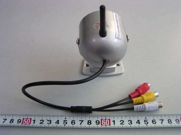
RAWLYD802CWAS
Dec 06, 2005Wireless Camera
Equipment Class
DXX - Part 15 Low Power Communication Device Transmitter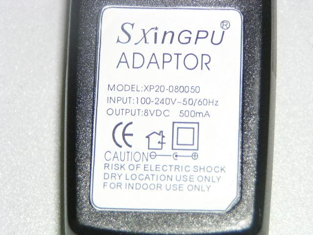
RAWLYD2G4CWAS
Nov 02, 2005Wireless Camera
Equipment Class
DXX - Part 15 Low Power Communication Device Transmitter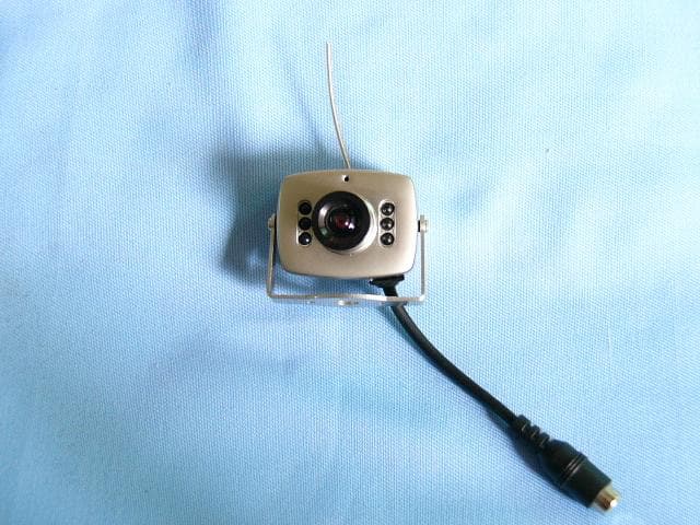
RAWLYD208CA
Nov 03, 2003Wireless Camera
Equipment Class
DXX - Part 15 Low Power Communication Device Transmitter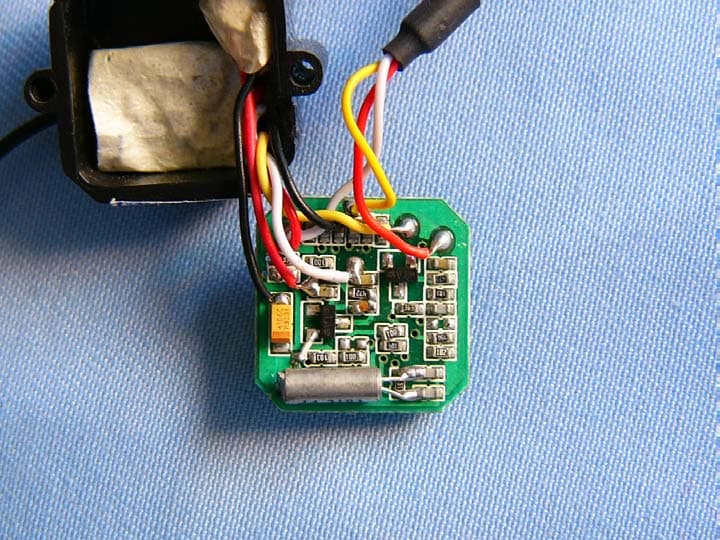
RAWLYD203CA
Aug 03, 2003Wireless Camera
Equipment Class
DXX - Part 15 Low Power Communication Device Transmitter