RF2IPLINK1000LOW POWER TRANSCEIVER
Helicomm, Inc.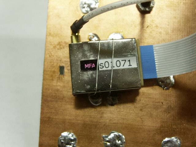
Click to zoom
Application Details
- Equipment Class
- DXX - Part 15 Low Power Communication Device Transmitter
- Date of Grant
- Mar 16, 2004
- Application Purpose
- Original Equipment
- Date of Application
- Mar 16, 2004
- Equipment Note
- LOW POWER TRANSCEIVER
- Frequency Range
- 907.50000000 - 917.70000000
- Company
- Helicomm, Inc.
- Country
- United States
Documents & Files
Document Text
Text extracted from the exhibit documents filed with the FCC. Open a document above to read the original.
Users Manual
Preliminary Manual The following is the layout instructions for your IP-Link 1000. This module should be installed in the same PCB as your system. The following is the layout rules/design rules: 1. The layout should include a ground plane under the module. The size of the ground plane is 4 by 6inches. 2. The Digital Input/ Output pins should be filtered. 3. Supply pin should have filter cut off in the hundred of hertz. Pin 14 is the supply pin. 4. FFC certification on the IP-Link 1000 was done using the following antenna: Nearson C321AT-925. In order to make Certification easier use the recommended antenna. 5. IP-Link 1000 has been certified to TCB, however your responsible for the your PCB certification. The following is the operational instruction for your IP-Link 1000. 1) Install the IP-Link 1000 on your board. 2) Using your installation CD, install the Helicomm IP-Software into you computer. 3) Apply power to your module. 4) Down load the firmware into the IP-Link 1000 module. "This device complies with Part 15 of the FCC Rules. Operation is subject to the following two conditions: (1) this device may not cause harmful interference, and (2) this device must accept any interference received, including interference that may cause undesired operation."
Users Manual
Operation Instructions The following is the operational instruction for your IP-Link 1000. 1) Install the IP_Link on your board. 2) Using your installation CD, install the Helicomm IP-Software inot you computer. 3) Apply power to your module. 4) Via your interface cable connect the IP-Link 1000 to the computer. 5) Down load the firmware into your module. "This device complies with Part 15 of the FCC Rules. Operation is subject to the following two conditions: (1) this device may not cause harmful interference, and (2) this device must accept any interference received, including interference that may cause undesired operation."
Users Manual
Preliminary Manual The following is the layout instructions for your IP-Link 1000. This module should be installed in the same PCB as your system. The following is the layout rules/design rules: 1. The layout should include a ground plane under the module. The size of the ground plane is 4 by 6inches. 2. The Digital Input/ Output pins should be filtered. 3. Supply pin should have filter cut off in the hundred of hertz. Pin 14 is the supply pin. 4. FFC certification on the IP-Link 1000 was done using the following antenna: Nearson C321AT-925. In order to make Certification easier use the recommended antenna. 5. IP-Link 1000 has been certified to TCB, however your responsible for the your PCB certification. The following is the operational instruction for your IP-Link 1000. 1) Install the IP-Link 1000 on your board. 2) Using your installation CD, install the Helicomm IP-Software into you computer. 3) Apply power to your module. 4) Down load the firmware into the IP-Link 1000 module. "This device complies with Part 15 of the FCC Rules. Operation is subject to the following two conditions: (1) this device may not cause harmful interference, and (2) this device must accept any interference received, including interference that may cause undesired operation."
Cover Letter(s)
Helicomm, Inc. 1947 Camino Vida Roble, Suite 109 Carlsbad, California 92008 Telephone: +1 (760) 918-0856 Fax: +1 (760) 918-0338 February 19, 2004 Federal Communications Commission, EQUIPMENT APPROVAL SERVICES, P.O Box 358315 Pittsburgh, PA 15251-5315 ATTN: Authorization & Evaluation Division PER: 47 CFR 0.457 and 0.459 RE: FCC ID: RF2IPLINK1000 Model#: IP-Link1000 Pursuant to Sections 0.457 (d)(1)(ii) and 0.459 of the Commission’s Rules, the Applicant hereby requests confidential treatment of some of the information accompanying this Application as listed below, i.e. A) List of Active Device B) Block Diagram C) Schematic Diagram D) Theory of Operation These materials contain trade secrets and proprietary information not customarily released to the public and the public disclosure of these matters might be harmful to the Applicant and provide unjustified benefits to its competitors. The Applicant understands that pursuant to Rule 0.457 (d)(1)(ii) disclosure of the Application and all accompanying documentation will not be made before the date of the Grant for this Application. Sincerely, Leon Gateno Helicomm Inc. Director of Hardware {00002547}
ID Label/Location Info
25mm x 18mm IP-Link ™ 1000 915MHz Module FCC ID: RF2IPLINK1000 S/N:
Operational Description
SpecificationsIP_ Link 1000 Frequency915 MHz Data Rate Typical32KBps ModulationFSK Microprocessor8051 RCVR Sensitivity-100dBm Tranmitter Range 100m RF Channels7 Transmit Power Max0 dBm Max Transmit Power Min-20 dBm Min Icc TX'er32mA Icc RCVR27mA Idle29uA Sleep.02uA
Parts List/Tune Up Info
Sheet1 reference des.Qty itemPart NumberManufacturer ValueCritical 1 C8 C4222C06_10p5_00Panasonic : ECJ-1VC1H100DC_10P_0603_NPO_G_50Critical C10-1123C06_6p85_00UMK105CH070DWC_6P8_0402_NPO_C_50Critical C14-1524C06_15p5_00UMK105CH150KWC_15P_0402_NPO_G_50Critical C2015C06_220p_00Panasonic : ECJ-1VC1H221JC_220P_0603_NPO_G_50Critical C2216C06_22p1_00Panasonic : ECJ-1VC1H220JC_22P_0603_NPO_J_50Critical C2317C06_150p_00Panasonic : ECJ-1VC1H151JC_150P_0603_NPO_J_50Critical C2418C06_150p_00Panasonic : ECJ-1VC1H151JC_150P_0603_NPO_I_50Critical C2619C06_12p1_00Panasonic : ECJ-1VC1H120JC_12P_0603_NPO_G_50Critical 10 C9 C131211C06_8p25_00Panasonic : ECJ-1VC1H080DC_8P2_0603_NPO_C_50Critical C1112CET_3U35_00Panasonic : ECS-TIAY335RC_3U3_TAN_8 U1113ICC_1010_00CHIPCON_CC1010Critical X1114XTE_14M7_00ECS Inc ECX_64AX14.7556Critical X2115XTS_32K0_00Seiko: SE2407CTX32.0KCritical C21 C25 C21 31633n 0603 C32117C04_1n01_00Taiyo Yuden LMK105BJ102KVC_1n0_402_X74_K_50 C19118C04_33n1_0033n 0603 C35119C04_1n01_00Taiyo Yuden LMK105BJ102KVC_1n0_402_X7R_K_50 L101122L08_12n5_00Coilcraft : 0603CS3n6XJBL_3N3_0603_KL73Critical L1123L08_3n35_00Coilcraft: 0805CS_030JL_3N3_0805_DCritical L32124L08_12n5_000402 12nCritical L41125L08_2n55_00Coilcraft : 085CS_020JL_2N5_0805_JCritical L2 L7226F06_15BB_00Murata : BLM15BB750PNIDBLM15BB750PNIDCritcal L3 127F06_15BB_00Murata: BLM15BB750PNIDBLM15BB750PNIDCritcal 30 R1,3-9, 19-27, 29-33, 34-4125310603 47K R10135R04_27K1_00Venkel : CR0402_16W_273JBR_27K_0402_G 36 R131137R04_82K1_00Venkel : CR0402_16W_823JBR_82K_0402_G 38 L8, L9, L10, L20, L21, L2260 Ohm 06030 Ohm 0603 J11?Digital Connector P3139?RF Connector Page 1
Parts List/Tune Up Info
Radio Tuning The only manufacturing tuning required is for the Crystal. This crystal is tuned for 14.7456MHz +/- .001 MHz. Channel selection is done via a PLL inside of the CC1010. Programming the PLL is done via the software in the MicroP . The MicroP is the 8051.
Test Report
FCC ID: RF2IPLINK1000 Page Number 2 of 14. AMENDED March 16, 2004 List Of General Information Required For Certification In Accordance with FCC Rules and Regulations, Volume II, Part 2 and to 15.249, Confidentiality Sub-Part 2.1033 (c)(1): Name and Address of Applicant: Helicomm 1947 Camino Vida Roble, Suite 109 Carlsbad, CA 92008 Manufacturer: Applicant (c)(2): FCC ID: RF2IPLINK1000 Model Number: IP-Link 1000 (c)(3): Instruction Manual(s): Please See Attached Exhibits (c)(4): Type of Emission: N/A (c)(5): FREQUENCY RANGE, MHz: 907.5 to 917.7 (c)(6): Power Rating, W: 0.016 Conducted 144 mw radiated 285.67 x 10 -6 v/m Switchable Variable x N/A 15.203: Antenna Requirement: The antenna is permanently attached to the EUT x The antenna uses a unique coupling The EUT must be professionally installed The antenna requirement does not apply MFA p0420001, d0430029
Test Report
FCC ID: RF2IPLINK1000 Transmitter Certification of FCC ID: RF2IPLINK1000 Model: IP-Link 1000 to Federal Communications Commission Rule Part 15.249, Confidentiality Date Of Amended Report: March 9, 2004 On the Behalf of the Applicant: Helicomm At the Request of: P.O. HC08803352 Helicomm 1947 Camino Vida Roble, Suite 109 Carlsbad, CA 92008 Attention of: Leon Gateno, Principle RF Engineer (760) 918-0856; FAX -0338 Email: [email protected] Supervised By: Morton Flom, P. Eng. MFA p0420001, d0430029 FCC ID: RF2IPLINK1000 List Of Exhibits (FCC Certification (Transmitters) - Revised 9/28/98) Applicant: Helicomm FCC ID: RF2IPLINK1000 By Applicant: 1. Letter of Authorization x 2. Confidentiality Request: 0.457 And 0.459 x 3. Identification Drawings, 2.1033(c)(11) x Label x Location of Label x Compliance Statement x Location of Compliance Statement 4. Photographs, 2.1033(c)(12) x 5. Documentation: 2.1033(c) (3) User Manual x (9) Tune Up Info x (10) Schematic Diagram x (10) Circuit Description x Block Diagram x Active Devices x By M.F.A. Inc.: A. Testimonial & Statement of Certification MFA p0420001, d0430029 FCC ID: RF2IPLINK1000 The applicant has been cautioned as to the following: 15.21 Information to User. The users manual or instruction manual for an intentional radiator shall caution the user that changes or modifications not expressly approved by the party responsible for compliance could void the user's authority to operate the equipment. 15.27(a) Special Accessories. Equipment marketed to a consumer must be capable of complying with the necessary regulations in the configuration in which the equipment is marketed. Where special accessories, such as shielded cables and/or special connectors are required to enable an unintentional or intentional radiator to comply with the emission limits in this part, the equipment must be marketed with, i.e. shipped and sold with, those special accessories. However, in lieu of shipping or packaging the special accessories with the unintentional or intentional radiator, the responsible party may employ other methods of ensuring that the special accessories are provided to the consumer, without additional charge. Information detailing any alternative method used to supply the special accessories for a grant of equipment authorization or retained in the verification records, as appropriate. The party responsible for the equipment, as detailed in § 2.909 of this chapter, shall ensure that these special accessories are provided with the equipment. The instruction manual for such devices shall include appropriate instructions on the first page of text concerned with the installation of the device that these special accessories must be used with the device. It is the responsibility of the user to use the needed special accessories supplied with the equipment. MFA p0420001, d0430029 FCC ID: RF2IPLINK1000 Table Of Contents Rule Description Page . Test Report 1 2.1033(c) General Information Required 2 . Standard Test Conditions and Engineering Practices 6 2.1046(a) ERP Carrier Power (Radiated) 7 2.1053(a) Field Strength of Spurious Radiation 8 2.1049(c)(1) Emission Masks (Occupied Bandwidth) 12 MFA p0420001, d0430029 FCC ID: RF2IPLINK1000 Page Number 1 of 14. Required information per ISO/IEC Guide 25-1990, paragraph 13.2: a) Test Report b) Laboratory: (FCC: 31040/SIT) (Canada: IC 2044) M. Flom Associates, Inc. 3356 N. San Marcos Place, Suite 107 Chandler, AZ 85225 c) Report Number: d0430029 d) Client: Helicomm 1947 Camino Vida Roble, Suite 109 Carlsbad, CA 92008 e) Identification: IP-Link 1000 FCC ID: RF2IPLINK1000 Description: Low Power Transmitter f) EUT Condition: Not required unless specified in individual tests. g) Report Date: March 9, 2004 EUT Received: February 2, 2004 h, j, k): As indicated in individual tests. i) Sampling method: No sampling procedure used. l) Uncertainty: In accordance with MFA internal quality manual. m) Supervised by: Morton Flom, P. Eng. n) Results: The results presented in this report relate only to the item tested. o) Reproduction: This report must not be reproduced, except in full, without written permission from this laboratory. MFA p0420001, d0430029 FCC ID: RF2IPLINK1000 Page Number 2 of 14. List Of General Information Required For Certification In Accordance with FCC Rules and Regulations, Volume II, Part 2 and to 15.249, Confidentiality Sub-Part 2.1033 (c)(1): Name and Address of Applicant: Helicomm 1947 Camino Vida Roble, Suite 109 Carlsbad, CA 92008 Manufacturer: Applicant (c)(2): FCC ID: RF2IPLINK1000 Model Number: IP-Link 1000 (c)(3): Instruction Manual(s): Please See Attached Exhibits (c)(4): Type of Emission: N/A (c)(5): FREQUENCY RANGE, MHz: 902.25 to 927.75 (c)(6): Power Rating, W: 0.016 Conducted 144 mw radiated 285.67 x 10 -6 v/m Switchable Variable x N/A 15.203: Antenna Requirement: The antenna is permanently attached to the EUT x The antenna uses a unique coupling The EUT must be professionally installed The antenna requirement does not apply MFA p0420001, d0430029 FCC ID: RF2IPLINK1000 Page Number 3 of 14. Industry Canada NIST MFA p0420001, d0430029 FCC ID: RF2IPLINK1000 Page Number 4 of 14. Subpart 2.1033 (continued) (c)(8): Voltages & Currents in All Elements in Final RF Stage, Including Final Transistor or Solid State Device: Collector Current, A = per manual Collector Voltage, Vdc = per manual Supply Voltage, Vdc = Bty 1.5 (c)(9): Tune-Up Procedure: Please See Attached Exhibits (c)(10): Circuit Diagram/Circuit Description: Including description of circuitry & devices provided for determining and stabilizing frequency, for suppression of spurious radiation, for limiting modulation and limiting power. Please See Attached Exhibits (c)(11): Label Information: Please See Attached Exhibits (c)(12): Photographs: Please See Attached Exhibits (c)(13): Digital Modulation Description: ___ Attached Exhibits _x_ N/A (c)(14): Test and Measurement Data: Follows MFA p0420001, d0430029 FCC ID: RF2IPLINK1000 Page Number 5 …
Text truncated - open the document above for the full version.
Test Setup Photos
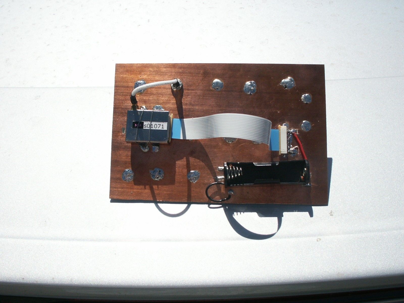
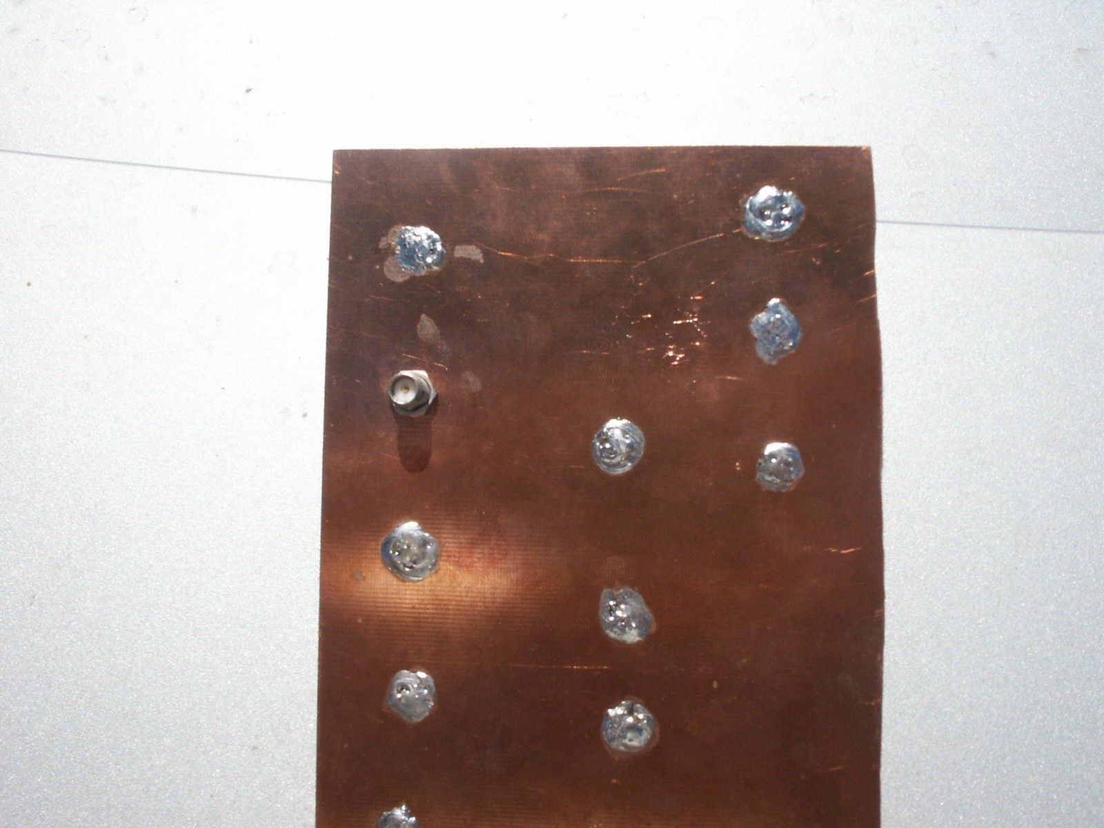
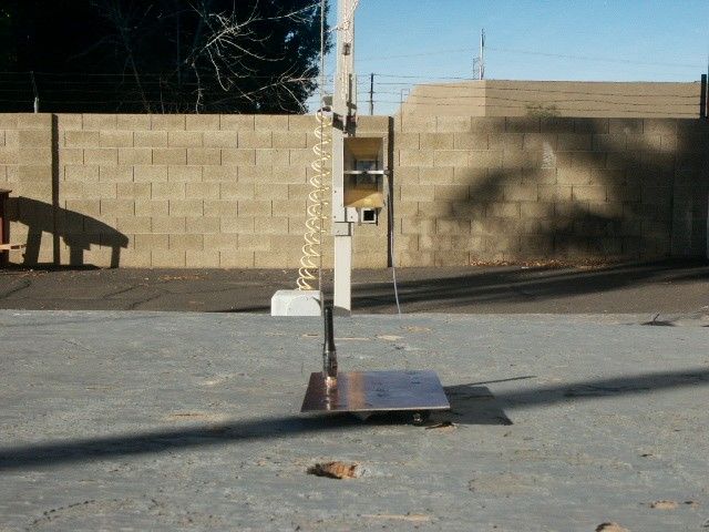
FCC ID: RF2IPLINK1000 Test Setup: Radiated Emissions MFA p0420001, d0420014
Contact Information
Applicant
Jack Sun(President)
Test Firm
M. Flom Associates, Inc.Morton Flom
Technical Specifications
| # | Rule Parts | Frequency Range | Power Output |
|---|---|---|---|
| 1 | 15C | 907.5 MHz - 917.7 MHz | - |
Other Applications from Helicomm, Inc.
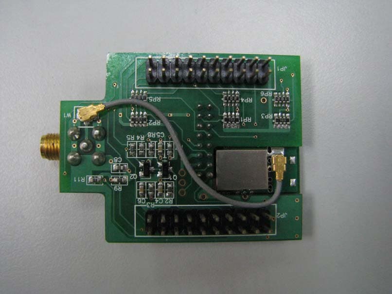
RF2IPLINK12235142
Aug 18, 2010Embedded Wireless Module
Equipment Class
DTS - Digital Transmission System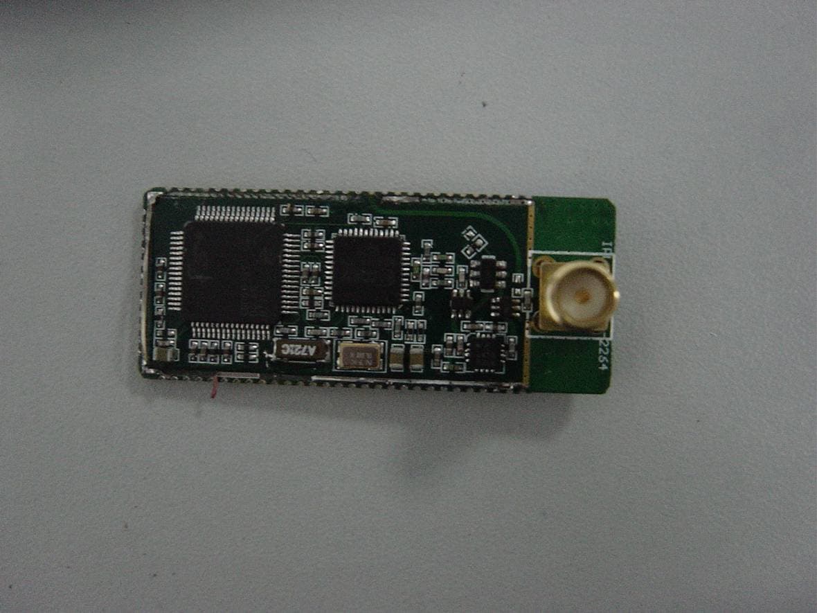
RF2IPLINK12212264
Feb 26, 2008Wireless Module
Equipment Class
DTS - Digital Transmission System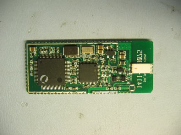
RF2IPLINKP220
Nov 30, 2005ZigBee Spread Spectrum Transceiver Module
Equipment Class
DTS - Digital Transmission System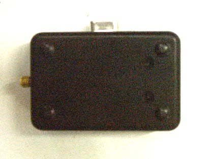
RF2A10IPLINK
Oct 23, 2003IP WIRELESS LINK MODULE
Equipment Class
DXX - Part 15 Low Power Communication Device Transmitter