RF2IPLINKP220ZigBee Spread Spectrum Transceiver Module
Helicomm, Inc.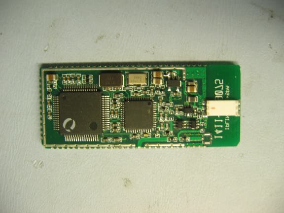
Click to zoom
Application Details
- Equipment Class
- DTS - Digital Transmission System
- Date of Grant
- Nov 30, 2005
- Application Purpose
- Original Equipment
- Date of Application
- Nov 30, 2005
- Equipment Note
- ZigBee Spread Spectrum Transceiver Module
- Frequency Range
- 2405.00000000 - 2480.00000000
- Company
- Helicomm, Inc.
- Country
- United States
Documents & Files
Document Text
Text extracted from the exhibit documents filed with the FCC. Open a document above to read the original.
Users Manual
Operation Instructions The following is the operational instruction for your IPLink1220. 1) Install the IPLink on your board 2) Using your installation CD, install the Helicomm IP-Software into your computer. 3) Apply power to your module. 4) Via your interface cable connect the IPLink to the computer. 5) Down load the firmware into your module. “ This device complies with Part 15 of the FCC Rules. Operation is subject to the following two conditions: (1) this device may not cause harmful interference, and (2) this device must accept any interference received, including interference that may cause undesired operation.” 6) Label your device with “Contains FCC ID: RF2IPLINKP220” CAUTION: The user is cautioned not to modify or change the IPLink1200 without explicit approval from Helicomm. If the user does not comply, authority to operate the equipment will be void. INFORMATION TO USER This device complies with Part 15 of the FCC Rules. Operation is subject to the following two conditions: (1) This device may not cause harmful interference, and (2) This device must accept any interference received, including interference that may cause undesired operation. This equipment has been tested and found to comply with the limits for Class B Digital Device, pursuant to Part 15 of the FCC Rules. These limits are designed to provide reasonable protection against harmful interference in a residential installation. This equipment generates and can radiate radio frequency energy and, if not installed and used in accordance with the instructions, may cause harmful interference to radio communications. However, there is no guarantee that interference will not occur in a particular installation. If this equipment does cause harmful interference to radio or television reception, which can be determined by turning the equipment off and on, the user is encouraged to try to correct the interference by one or more of the following measures. • Reorient or relocate the receiving antenna • Increase the separation between the equipment and receiver • Connect the equipment into an outlet on a circuit different from that to which the receiver is connected • Consult the dealer or an experienced radio/TV technician for help Any changes or modifications not expressly approved by the party responsible for compliance could void the user’s authority to operate the equipment. HUMAN EXPOSURE STATEMENT This information is necessary to ensure that equipment installers, operators and users are made aware of the dangers of exposure to radio frequency radiation and that the Module shall be installed and operated in compliance with 47 CFR Part 15, Subpart C of the FCC Rules and Regulations. In all applications and uses, compliance with current FCC RF regulations limiting human exposure to radio frequency exposure is dependent upon installation, operation and use of the equipment in accordance with all instructions provided
Attestation Statements
26/09/05 Nemko Canada Inc 303 River Road Ottawa, Ontario, Canada K1V 1H2 Attn: Director of Certification Authority to Act as Agent On our behalf, I appoint _Nemko Canada Inc__, (Name and address). to act as our agent in the preparation of this application for equipment certification. I certify that submitted documents properly describe the device or system for which equipment certification is sought. I also certify that each unit manufactured, imported or marketed, as defined in the Federal Communications Commission’s regulations will have affixed to it a label identical to that submitted for approval with this application. For instances where our authorized agent signs the application for certification on our behalf, I acknowledge that all responsibility for complying with the terms and conditions for certification, as specified by Nemko Canada Inc, still resides with __Helicomm Inc 1947 Camino Vida Roble Suite 109___( applicant name and address). Dated this 12 Day of October 20 05 Agency agreement expiration date: 12 Jan 06 By: Leon Gateno Signature Printed Title: Director Hardware On behalf of : Helicomm Inc Telephone: 760-918-0856
Cover Letter(s)
Cover Letter for the FCC ID RF2IPLinkP220 Module v1.2 PROPRIETARY & CONFIDENTIAL Cover Letter for the FCC ID RF2IPLinkP220 Module Date: 11, 30, 2005 Version: 1.2 PDF created with pdfFactory trial version www.pdffactory.com Cover Letter for the FCC ID RF2IPLinkP220 Module v1.2 PROPRIETARY & CONFIDENTIAL PDF created with pdfFactory trial version www.pdffactory.com v1.2—11, 30, 2005 PROPRIETARY & CONFIDENTIAL Page i © 2003 Helicomm, Inc. All rights reserved. This publication is proprietary and confidential and is not for disclosure outside Helicomm, Inc., and their affiliates. No part of this publication may be reproduced, adapted, or translated in any form or by any means without prior written authorization of Helicomm, Inc. Information published here is current or planned as of the date of publication of this document. Because we are improving and adding features to our products continuously, the information in this publication is subject to change without notice. Revision and Iteration History Version Publication Date Authors Summary of Changes and Updates 1.1 9/24/06 Leon Gateno Original 1.2 11/30/05 Leon Gateno Update. PDF created with pdfFactory trial version www.pdffactory.com v1.2—11, 30, 2005 PROPRIETARY & CONFIDENTIAL Page ii Table of Contents 1 Introduction..................................................................................................................1 2 List of Requirements...................................................................................................2 2.1 First Requirement............................................................................................................2 2.2 Second Requirement.......................................................................................................2 2.3 Third Requirement...........................................................................................................3 2.4 Fourth Requirement........................................................................................................3 2.5 Fifth Requirement............................................................................................................3 2.6 Sixth Requirement...........................................................................................................3 2.7 Seventh Requirement......................................................................................................4 2.8 Eighth Requirement.........................................................................................................4 PDF created with pdfFactory trial version www.pdffactory.com Cover Letter for the FCC ID RF2IPLinkP220 Module Introduction v1.2—11, 30, 2005 PROPRIETARY & CONFIDENTIAL Page 1 1 Introduction FCC ID RF2IPLINKP220 is a module hence Helicomm would like to apply for modular approval. This document will explain how Helicomm plans to comply with the 8 requirements for a modular approval. Note: In this document System Designer refers to the design house that will use our module on there system. The FCC ID RF2IPLINKP220 module is sold to companies that should be aware of the FCC. PDF created with pdfFactory trial version www.pdffactory.com Cover Letter for the FCC ID RF2IPLinkP220 Module List of Requirements v1.2—11, 30, 2005 PROPRIETARY & CONFIDENTIAL Page 2 2 List of Requirements The following are the 8 requirements to meet modular approval. Also included is a brief discussion of how we plan to comply with this modular approval. 2.1 First Requirement The modular transmitter must have its own RF shielding. This is intended to ensure that the module does not have to rely upon the shielding provided by the device into which it is installed in order for all modular transmitter emissions to comply with Part 15 limits. It is also intended to prevent coupling between the RF circuitry of the module and any wires or circuits in the device into which the module is installed. Such coupling may result in non-compliant operation. The FCC ID RF2IPLINKP220 is enclosed in its own shield. Second, the board provides a ground plain to any traces in both top and bottom layers, hence minimum radiation of the signal by the trace. Third, the unit is no bigger than 40mm by 20mm. In order to get coupling of any significance, the interfering signal has to have a frequency greater than 1 GHz. No expose signals carry such frequencies. All traces affected by such frequencies are completely isolated. Power supply traces filter out frequencies above 1GHz. The only RF input/output to the module is via the antenna. This input /output frequency via the antenna is filtered by passive filters and the antenna. The frequency range is from 2.4 to 2.485GHz. 2.2 Second Requirement The modular transmitter must have buffered modulation/data inputs (if such inputs are provided) to ensure that the module will comply with Part 15 requirements under conditions of excessive data rates or over-modulation. The modular transmitter must have buffered modulation/data inputs (if such inputs are provided) to ensure that the module will comply with Part 15 requirements under conditions of excessive data rates or over-modulation. Chip rate for this system is fixed there for the over modulation will no occur. Also, the system is set up to shut down if it receives any data rates greater or lower than the standard data rate. PDF created with pdfFactory trial version www.pdffactory.com Cover Letter for the FCC ID RF2IPLinkP220 Module List of Requirements v1.2—11, 30, 2005 PROPRIETARY & CONFIDENTIAL Page 3 2.3 Third Requirement The modular transmitter must have its own power supply regulation. This is intended to ensure that the module will comply with Part 15 requirements regardless of the design of the power supplying circuitry in the device into which the module is installed. All of the critical circuits in the Transceivers have there own regulator. Also, there is filtering capacitors to reduce the noise coming into the unit. Also, under every t…
Text truncated - open the document above for the full version.
Cover Letter(s)
10/12/06 Nemko 11696 Sorrento Valley Rd. San Diego CA, 92121 USA Re: Request of Confidentiality for FCC ID#: RF2IPLINKP220 Pursuant to Sections 0.457(d)(I)(ii) and 0.459 of the Commission’s Rules, the Applicant hereby requests confidential treatment of information accompanying as outlined below: Schematics, Parts List, Operating Description, Block Diagrams The above materials contain trade secrets and proprietary information not customarily released to the public. The public disclosure of these matters might be harmful to the Applicant and provide unjustified benefits to its competitors. The Applicant understands that pursuant to Rule 0.457(d)(I)(ii), disclosure of this Application and all accompanying documentation will not be made before the date of the Grant for this Application. Sincerely, Leon Gateno Director of Hardware Helicomm Inc
External Photos
with shield
ID Label/Location Info
RF2IPLINKP220 –. Label actual size does not allow for FCC warning to be included. FCC Warning to be added to outside of final product per installation instructions. RF2IPLINKP220
ID Label/Location Info
& with shield
Internal Photos
with shield
Test Report
Nemko USA, Inc. 11696 Sorrento Valley Rd., Suite F San Diego, CA 92121-1024 Phone (858) 793-9911 Fax (858) 793-9914 Number of Pages: 26 PART 15.247 TEST REPORT For The 2.4 GHz System Model: IP-LinK 1220-2133 FCC ID# RF2IPLINKP220. PREPARED FOR: Helicomm 1947 Camino Vida Roble, Suite 109 Carlsbad, CA 92008 PREPARED ON SEPTEMBER 30, 2005 REPORT NUMBER 2005 090314R1-FCC PROJECT NUMBER: 25-314-HELR1 Nemko USA FCC Part 15.247 TEST REPORT # 2005 090314R1-FCC FCC ID #: RF2IPLINKP220 Page 2 of 26 DOCUMENT HISTORY REVISION DATE COMMENTS - September 30, 2005 Prepared By: Alan Laudani - December 17, 2004 Initial Release: F.R. Fleury NOTE: Nemko USA, Inc. hereby makes the following statements so as to conform to Chapter 10 (Test Reports) Requirements of ANSI C63.4 (2003 ) “Methods and Measurement of Radio-Noise Emissions from Low-Voltage Electrical and Electronic Equipment in the Range of 9 kHz to 40 GHz”: o The unit described in this report was received at Nemko USA, Inc.'s facilities on September 28, 2005 . Testing was performed on the unit described in this report on September 28, 2005 to September 29, 2005 o The Test Results reported herein apply only to the Unit actually tested, and to substantially identical Units. o This report does not imply the endorsement of the Federal Communications Commission (FCC), NVLAP or any other government agency. This Report is the property of Nemko USA, Inc., and shall not be reproduced, except in full, without prior written approval of Nemko USA, Inc. However, all ownership rights are hereby returned unconditionally to Helicomm, and approval is hereby granted to Helicomm and its employees and agents to reproduce all or part of this report for any legitimate business purpose without further reference to Nemko USA, Inc. Nemko USA FCC Part 15.247 TEST REPORT # 2005 090314R1-FCC FCC ID #: RF2IPLINKP220 Page 3 of 26 TABLE OF CONTENTS DOCUMENT HISTORY....................................................................................................................................2 CERTIFICATION...............................................................................................................................................4 1. ADMINISTRATIVE DATA AND TEST SUMMARY.............................................................................5 ADMINISTRATIVE DATA.........................................................................................................................................5 TEST SUMMARY....................................................................................................................................................5 2. SYSTEM CONFIGURATION..................................................................................................................6 DESCRIPTION AND METHOD OF EXERCISING THE EUT......................................................................................6 SYSTEM COMPONENTS AND POWER CABLES.....................................................................................................6 DEVICE INTERCONNECTION AND I/O CABLES......................................................................................................6 DESIGN MODIFICATIONS FOR COMPLIANCE........................................................................................................7 3. DESCRIPTION OF TEST SITE AND EQUIPMENT............................................................................8 DESCRIPTION OF TEST SITE................................................................................................................................8 4. DESCRIPTION OF TESTING METHODS............................................................................................9 INTRODUCTION.....................................................................................................................................................9 CONFIGURATION AND METHODS OF MEASUREMENTS FOR CONDUCTED EMISSIONS........................................9 CONFIGURATION AND METHODS OF MEASUREMENTS FOR FREQUENCY IDENTIFICATION...............................10 CONFIGURATION AND METHODS OF MEASUREMENTS FOR RADIATED EMISSIONS..........................................11 5. TEST RESULTS.....................................................................................................................................12 BANDWIDTH16 APPENDICES APPENDIX A....................................................................................................................................................23 LOWER POWERED MODEL IP-LINK 1220-2033 POWER LEVELS, PEAK POWER DENSITY AND SPURIOUS EMISSIONS. ERROR! BOOKMARK NOT DEFINED. B. CONDUCTED & RADIATED EMISSIONS MEASUREMENT UNCERTAINTIES.....................................................23 C. NEMKO USA, INC.’S TEST EQUIPMENT & FACILITIES CALIBRATION PROGRAM.........................................25 Nemko USA FCC Part 15.247 TEST REPORT # 2005 090314R1-FCC FCC ID #: RF2IPLINKP220 Page 4 of 26 CERTIFICATION The Radio Frequency Interference (RFI) testing, data evaluation and this report have been prepared by Nemko USA, Inc., an independent electromagnetic compatibility consulting and test laboratory. The testing and data collection were accomplished in accordance with the requirements of the ANSI, C63.4-2003 standard and the applicable sections of FCC, Part 15, Subpart B for Class "A" equipment. The testing was also accomplished in accordance with Industry Canada's ICES-003 standard for unintentional radiating device per EMCAB-3, Issue 3 (May 1998). Refer to the Administrative Summary for a description of the test sample. I certify the data, data evaluation and equipment configuration herein to be a true and accurate representation of the sample's radio frequency interference emission characteristics, as of the test date(s), and for the design of the test sample used to compile this report. FR Fleury Floyd Fleury Frontline Manager Nemko USA FCC Part 15.247 TEST REPORT # 2005 090314R1-FCC…
Text truncated - open the document above for the full version.
Test Setup Photos
Conducted Output Power Bandwidth Spurious Emissions at Antenna Terminals Peak Power & Field Strength of Spurious Radiation 3 METERS EUT NON-CONDUCTING TURN-TABLE 0.8 METER VARIABLE SEARCH HEIGHT (1 TO 4 m) TO TEST RECEIVER/SPECTRUM ANALYZER SEARCH ANTENNA EUT ATTENUATION SPECTRUM ANALYZER
Contact Information
Applicant
Jack Sun(President)
Technical Contact
Nemko Canada Inc.Russell Grant
[email protected]613-737-9680
303 River Road · Ottawa, Ontario · Canada
Test Firm
Nemko USA, Inc. - San Diego EMC DivisionRicky Hill
Technical Specifications
| # | Rule Parts | Frequency Range | Power Output |
|---|---|---|---|
| 1 | 15C | 2.40 GHz - 2.48 GHz | 4.40 mW |
Other Applications from Helicomm, Inc.
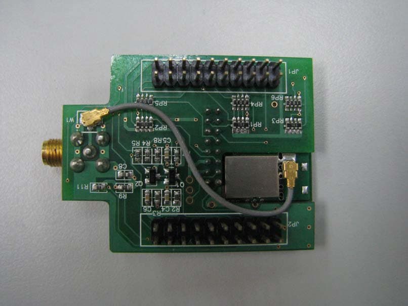
RF2IPLINK12235142
Aug 18, 2010Embedded Wireless Module
Equipment Class
DTS - Digital Transmission System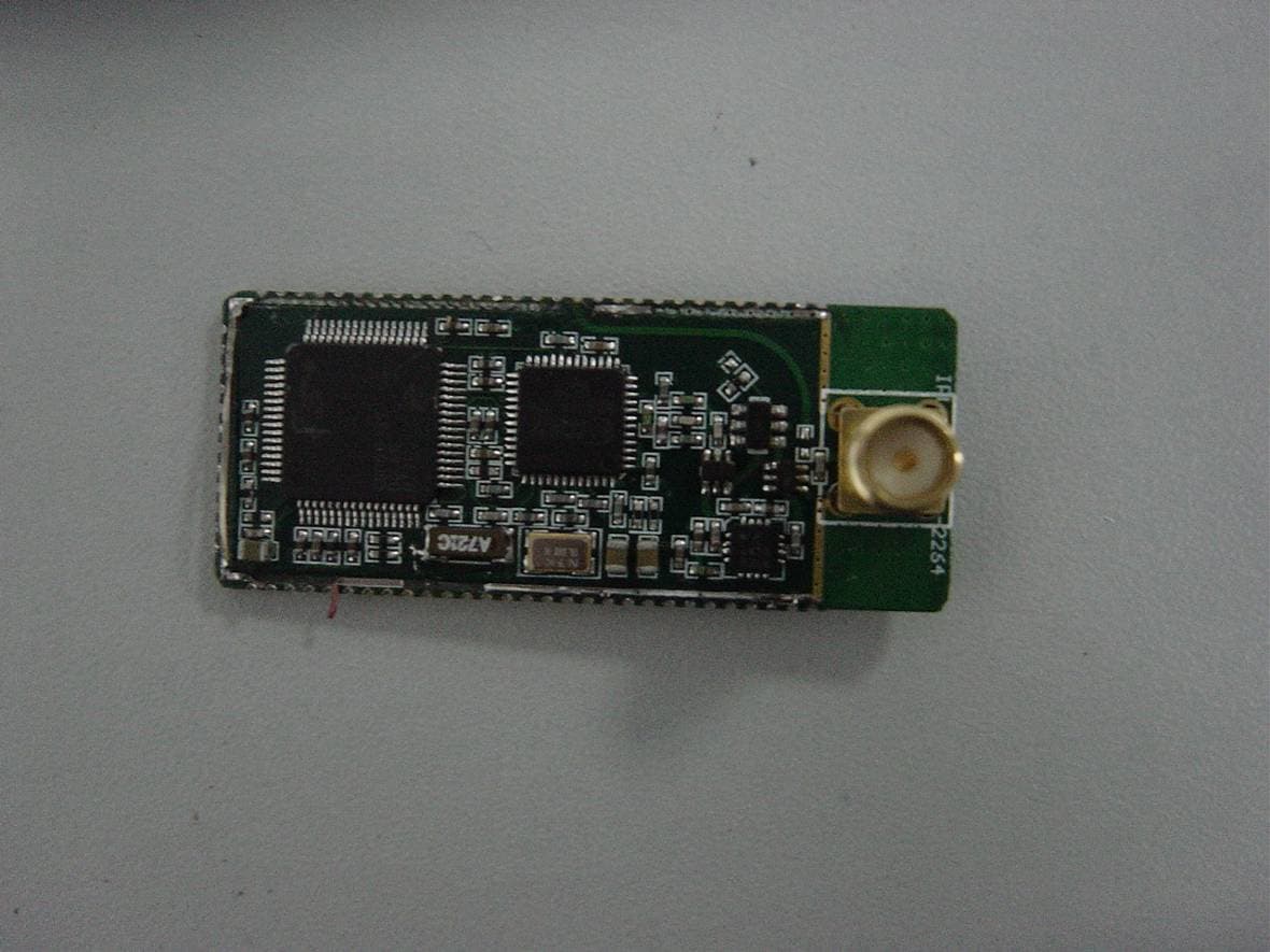
RF2IPLINK12212264
Feb 26, 2008Wireless Module
Equipment Class
DTS - Digital Transmission System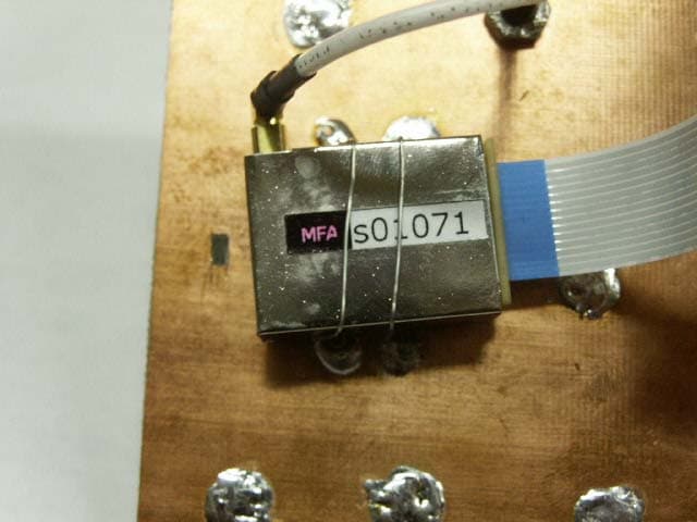
RF2IPLINK1000
Mar 16, 2004LOW POWER TRANSCEIVER
Equipment Class
DXX - Part 15 Low Power Communication Device Transmitter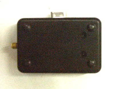
RF2A10IPLINK
Oct 23, 2003IP WIRELESS LINK MODULE
Equipment Class
DXX - Part 15 Low Power Communication Device Transmitter