RF2IPLINK12235142Embedded Wireless Module
Helicomm, Inc.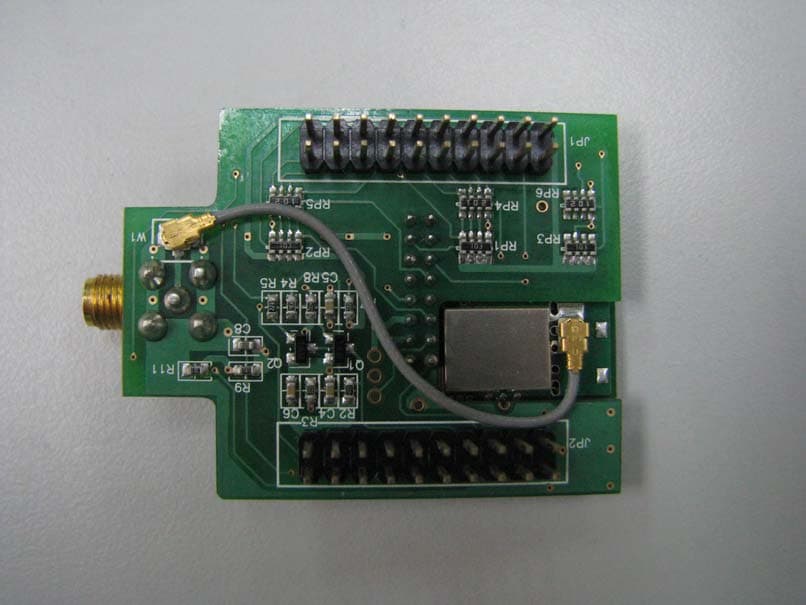
Click to zoom
Application Details
- Equipment Class
- DTS - Digital Transmission System
- Date of Grant
- Aug 18, 2010
- Application Purpose
- Original Equipment
- Date of Application
- Aug 18, 2010
- Equipment Note
- Embedded Wireless Module
- Frequency Range
- 2405.00000000 - 2480.00000000
- Company
- Helicomm, Inc.
- Country
- United States
Documents & Files
Document Text
Text extracted from the exhibit documents filed with the FCC. Open a document above to read the original.
Users Manual
IP•Link 1223 Embedded Wireless Module User Manual Version 1.1.02 Helicomm, Inc. www.helicomm.com Version 1.1.02 IP-Link 1223 User Manual Helicomm, Inc. Page i © 2010 Helicomm, Inc. All rights reserved. No part of this publication may be reproduced, adapted, or translated in any form or by any means without prior written authorization of Helicomm, Inc. Information published here is current or planned as of the date of publication of this document. Because we are improving and adding features to our products continuously, the information in this publication is subject to change without notice. Trademarks Helicomm, IPWINS, IP-Link, WIN-Gate, and IP-Net are trademarks of Helicomm, Inc. ZigBee is a trademark of the ZigBee Alliance. All other product names mentioned in this publication are trademarks of their respective owners. Revision and Iteration History Version Publication Date Authors Summary of Changes and Updates 1.0.00 12/17/2008 Yr.Qie Initial Draft 1.1.00 07/20/2009 Wt.Wu Modify AT registers,the comment parameters about IO ports . And modify the formula for get IP-Link 1223 temperature. 1.1.01 07/09/2101 Frank Tung Revised dimension 1.1.02 08/03/2010 Frank Tung Added FCC information Version 1.1.02 IP-Link 1223 User Manual Helicomm, Inc. Page ii FCC Information The equipment has been tested and found to comply with the limits for a Class B Digital Device, pursuant to part 15 of the FCC Rules. These limits are designed to provide reasonable protection against harmful interference in a residential installation. This equipment generates uses and can radiate radio frequency energy and, if not installed and used in accordance with the instruction, may cause harmful interference to radio communication. However, there is no grantee that interference will not occur in a particular installation. If this equipment dose causes harmful interference to radio or television reception, which can be determined by turning the equipment off and on, the user is encouraged to try to correct the interference by one or more of the following measures: --Reorient or relocate the receiving antenna. --Increase the separation between the equipment and receiver. --Connect the equipment into an outlet on a circuit different from that to which the receiver is connected. --Consult the dealer or an experienced radio/TV technician for help. This device complies with Part 15 of the FCC Rules. Operation is subject to the following two conditions: (1) this device may not cause harmful interference, and (2) this device must accept any interference received, including interference that may cause undesired operation. The changes or modifications not expressly approved by the party responsible for compliance could void the user’s authority to operate the equipment. To compl y with the RF exposure compl iance requirements, thi s device and its antenna must not be co-located or operating to conjunction with any other antenna or transmitter. This equipment should be installed and operated with minimum distance 20cm between the radiator & your body. To OEM installer: 1. ID label on the final system must be labeled with "Contains FCC ID: RF2IPLINK12235142 / IC: 8576A-IPLINK5142" or "C ontain transmitter module FCC ID: RF2IPLINK12235142 / IC: 8576A- IPLINK 5142 ". 2.In the user manual, final system integrator must be ensured that there is no instruction provided in the user manual to install or remove the transmitter module. 3. Transmitter module must be installed and used in strict accordance with the manufacturer is instructions as described in the user documentation that comes with the product. This device complies with the following radio frequency and safety standards. The user manual of the final host system must contain the following statements: This equipment has been tested and found to comply with the limits for a Class B Digital Device, pursuant to part 15 of the FCC Rules. These limits are designed to provide reasonable protection against harmful interference in a residential installation. This equipment generates, uses and can radiate radio frequency energy and, if not installed and used in accordance with the instruction, may cause harmful interference to radio communication. However, there is no grantee that interference will not occur in a particular installation. If this equipment dose causes harmful interference to radio or television reception, which can be determined by turning the equipment off and on, the user is encouraged to try to correct the interference by one or more of the following measures: --Reorient or relocate the receiving antenna. --Increase the separation between the equipment and receiver. Version 1.1.02 IP-Link 1223 User Manual Helicomm, Inc. Page iii --Connect the equipment into an outlet on a circuit different from that to which the receiver is connected. --Consult the dealer or an experienced radio/TV technician for help. This device complies with Part 15 of the FCC Rules. Operation is subject to the following two conditions: (1) this device may not cause harmful interference, and (2) this device must accept any interference received, including interference that may cause undesired operation. The changes or modifications not expressly approved by the party responsible for compliance could void the user’s authority to operate the equipment. To compl y with the RF exposure compl iance requirements, thi s device and its antenna must not be co-located or operating to conjunction with any other antenna or transmitter. This equipment should be installed and operated with minimum distance 20cm between the radiator & your body. “This device has been designed to operate with the antennas listed below, and having a maximum gain of [3] dB. Antennas not included in this list or having a gain greater than [3] dB are strictly prohibited for use with this device. The required antenna impedance is [50] ohms.” “To reduce potential radio interference to other users, the antenna type and its gain should be …
Text truncated - open the document above for the full version.
External Photos
FCC ID. :RF2IPLINK12235142 Page A1 of A3 IC ID: 8576A-IPLINK5142 ETC Report No.: 10-07-MAS-231 ANNEX A: EXTERNAL CONSTRUCTION PHOTOS OF EUT 1. Outside view 1 of EUT 2. Outside view 2 of EUT FCC ID. :RF2IPLINK12235142 Page A2 of A3 IC ID: 8576A-IPLINK5142 ETC Report No.: 10-07-MAS-231 3. Outside view 3 of EUT 4. Outside view 4 of EUT FCC ID. :RF2IPLINK12235142 Page A3 of A3 IC ID: 8576A-IPLINK5142 ETC Report No.: 10-07-MAS-231 5. Antenna Connect
ID Label/Location Info
ID Label_Location FCC ID: RF2IPLINK12235142 IC: 8576A-IPLINK5142
Internal Photos
FCC ID. :RF2IPLINK12235142 Page B1 of B4 IC ID: 8576A-IPLINK5142 ETC Report No.:10-07-MAS-231 ANNEX B: INTERNAL CONSTRUCTION PHOTOS OF EUT 1. Inside View 1 of EUT 2. Inside View 2 of EUT FCC ID. :RF2IPLINK12235142 Page B2 of B4 IC ID: 8576A-IPLINK5142 ETC Report No.:10-07-MAS-231 3. Front view of PCB1 4. Rear view of PCB1 FCC ID. :RF2IPLINK12235142 Page B3 of B4 IC ID: 8576A-IPLINK5142 ETC Report No.:10-07-MAS-231 5. Front view of PCB2 6. Rear view of PCB2 FCC ID. :RF2IPLINK12235142 Page B4 of B4 IC ID: 8576A-IPLINK5142 ETC Report No.:10-07-MAS-231 7. Front view of PCB3 8. Rear view of PCB3
RF Exposure Info
FCC ID: RF2IPLINK12235142 Sheet 1 of 2 Sheets IC ID: 8576A-IPLINK5142 ETC Report No. : 10-07-MAS-231 Rev. No 1.0 MAXIMUM PERMISSIBLE EXPOSURE Standard Applicable Section 15.247 (b)(5) : Systems operating under the provisions of this section shall be operated in a manner that ensures that the public is not exposed to radio frequency energy levels in excess of the Commission's guidelines. See § 1.1307(b)(1) of this Chapter. Section 1.1310: The criteria listed in the following table shall be used to evaluate the environment impact of human exposure to radio frequency radiation as specified in 1.1307(b) LIMITS FOR MAXIMUM PERMISSIBLE EXPOSURE (MPE) Frequency Range (MHz) Electric Field Strength (V/m) Magnetic Field Strength (A/m) Power Density (mW/cm 2 ) Average Time (Minutes) (A) Limits for Occupational/control Exposures 300-1500 -- -- F/300 6 1500-100,000 -- -- 5 6 (B) Limits for General Population/Uncontrolled Exposures 300-1500 -- -- F/1500 30 1500-100,000 -- -- 1.0 30 F = Frequency in MHz Calculations Friis transmission formula: P d = ( P out * G ) / ( 4 * pi * r 2 ) Where P d = power density in mW/cm 2 P out = output power to antenna in mW G = gain of antenna in linear scale pi = 3.1416 r = distance between observation point and center of the radiator in cm The limit of P d is 1 mW/cm 2 . If we know the maximum gain of the antenna and the total power input to the antenna, through the calculation, we will know the distance where the P d at 20 cm is meet the limit of MPE. FCC ID: RF2IPLINK12235142 Sheet 2 of 2 Sheets IC ID: 8576A-IPLINK5142 ETC Report No. : 10-07-MAS-231 Rev. No 1.0 Result : :: : (Worse case mode) Operation Frequency (GHz) Distance (cm) Maximum Peak Output Power (dBm) Antenna Gain (dBi) Power Density (mW/cm 2 ) Limit (mW/cm 2 ) 2.445 20 21.36 3.0 0.054291 1 The P d at 20 cm distance calculated from the Friis transmission formula is mush smaller than the limit requirement 1 mW/cm 2 . The Installation Manual instructs the user to install the device such that it has a separation of at least 20 cm from persons to comply with the FCC's requirements. This separation of 20 cm more than meets the FCC's and Industry Canada RF exposure requirements.
Test Report
FCC ID. :RF2IPLINK12235142 Sheet 1 of 46 Sheets IC ID: 8576A-IPLINK5142 ETC Report No. : 10-07-MAS-231 Rev. No 1.0 CONFORMANCE TEST REPORT FOR FCC 47 CFR, Part 15 Subpart C and Canada RSS-210 Report No.: 10-07-MAS-231 Client: Helicomm Inc. Product: Embedded Wireless Module Model: IP-Link 1223-5142 FCC ID: RF2IPLINK12235142 IC ID: 8576A-IPLINK5142 Manufacturer/supplier: Helicomm Inc. Date test item received: 2010/07/21 Date test campaign completed: 2010/07/30 Date of issue: 2010/07/30 The test result onl y corresponds to the tested sample. It is not permitted to copy this report, in part or in full, without the permission of the test laboratory. Total number of pages of this test report: 46 pages Total number of pages of photos: External photos 3 pages Internal photos 4 pages Setup photos 3 pages Test Engineer Checked By Approved By Ivan Tsai James Cheng Joe Hsieh ELECTRONICS TESTING CENTER, TAIWAN NO.8, LANE 29, WENMING RD., LESHAN TSUEN, GUISHAN SHIANG, TAOYUAN COUNTY, TAIWAN 33383, R.O.C.TAIWAN, R.O.C. TEL: (03) 3276170~4 INT: +886-3-3276170~4 FAX: (03) 3276188 INT: +886-3-3276188 FCC ID. :RF2IPLINK12235142 Sheet 2 of 46 Sheets IC ID: 8576A-IPLINK5142 ETC Report No. : 10-07-MAS-231 Rev. No 1.0 Client : Helicomm Inc. Address : 6540 Lusk Blvd. Suite C155 San Diego, CA 92121 Manufacturer : Helicomm Inc. Address : 6540 Lusk Blvd. Suite C155 San Diego, CA 92121 EUT : Embedded Wireless Module Trade name : Helicomm Model No. : IP-Link 1223-5142 Power Source : 3.6Vdc Regulations applied : FCC 47 CFR, Part 15 Subpart C (2009) Canada RSS-210 Issue 7 (2007) / RSS-Gen Issue 2 (2007) The testing described in this report has been carried out to the best of our knowledge and ability, and our responsibility is limited to the exercise of reasonable care. This certification is not intended to believe the sellers from their legal and/or contractual obligations. The compliance test is only certified for the test equipment and the results of the testing report relate only to the item tested. The compliance test of this report was conducted in accordance with the appropriate standards. It’s not intention to assure the quality and performance of the product. This report shall not be reproduced except in full, without the approval of ETC. This report must not be used by the client to claim product endorsement by NVLAP or any agency of the U.S. Government. Laboratory Introduction: Electronics Testing Center, Taiwan is recognized, filed and mutual recognition arrangement as following: 1 ISO9001: TüV Product Service 2 ISO/IEC 17025: BSMI, CNLA, DGT, NVLAP, CCIBLAC, UL, Compliance 3 Filing: FCC, Industry Canada, VCCI 4 MRA: Australia, Hong Kong, New Zealand, Singapore, USA, Japan, Korea, China, APLAC through TAF 5 FCC Registration Number: 90588, 91094, 91095 h Industry Canada Site Regisitation number: IC 2949A-1 NVLAP Lab Code 200133-0 FCC ID. :RF2IPLINK12235142 Sheet 3 of 46 Sheets IC ID: 8576A-IPLINK5142 ETC Report No. : 10-07-MAS-231 Rev. No 1.0 Table of Contents Page 1 GENERAL INFORMATION ............................................................................................... 5 1.1 Product Description.............................................................................................................. 5 1.2 Characteristics of Device ..................................................................................................... 5 1.3 Test Methodology ................................................................................................................ 5 1.4 Test Facility.......................................................................................................................... 5 1.5 Test Summary ...................................................................................................................... 5 2 PROVISIONS APPLICABLE.............................................................................................. 6 2.1 Definition ............................................................................................................................. 6 2.2 Requirement for Compliance ............................................................................................... 7 2.3 Restricted Bands of Operation .............................................................................................9 2.4 Labeling Requirement .......................................................................................................... 9 2.5 User Information ................................................................................................................ 10 3. SYSTEM TEST CONFIGURATION ................................................................................ 11 3.1 Devices for Tested System.................................................................................................11 4 CONDUCTED EMISSION MEASUREMENT ................................................................ 12 4.1 Standard Applicable ........................................................................................................... 12 4.2 Measurement Procedure.....................................................................................................12 4.3 Conducted Emission Data .................................................................................................. 13 4.4 Result Data Calculation ..................................................................................................... 15 4.5 Conducted Measurement Equipment ................................................................................. 15 5 ANTENNA REQUIREMENT ............................................................................................ 16 5.1 Standard Applicable ........................................................................................................... 16 5.2 Antenna Construction and Directional Gain ...................................................................... 16 6 EMISSION BANDWIDTH MEASUREMENT .....…
Text truncated - open the document above for the full version.
Contact Information
Applicant
Jack Sun(President)
Test Firm
Electronics Testing Center, TaiwanWin-Po Tsai
Technical Specifications
| # | Rule Parts | Frequency Range | Power Output |
|---|---|---|---|
| 1 | 15C | 2.40 GHz - 2.48 GHz | 137.00 mW |
Other Applications from Helicomm, Inc.
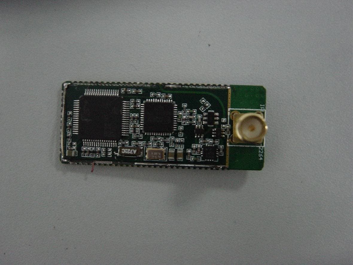
RF2IPLINK12212264
Feb 26, 2008Wireless Module
Equipment Class
DTS - Digital Transmission System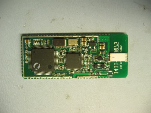
RF2IPLINKP220
Nov 30, 2005ZigBee Spread Spectrum Transceiver Module
Equipment Class
DTS - Digital Transmission System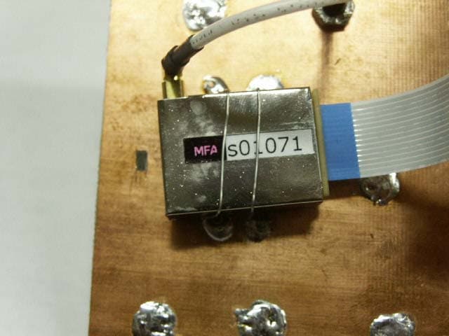
RF2IPLINK1000
Mar 16, 2004LOW POWER TRANSCEIVER
Equipment Class
DXX - Part 15 Low Power Communication Device Transmitter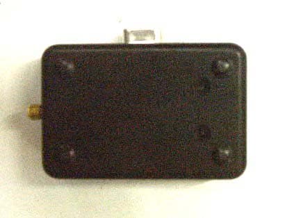
RF2A10IPLINK
Oct 23, 2003IP WIRELESS LINK MODULE
Equipment Class
DXX - Part 15 Low Power Communication Device Transmitter