RHHPAB01Smart Energy In Wall Meter
Philio Technology Corporation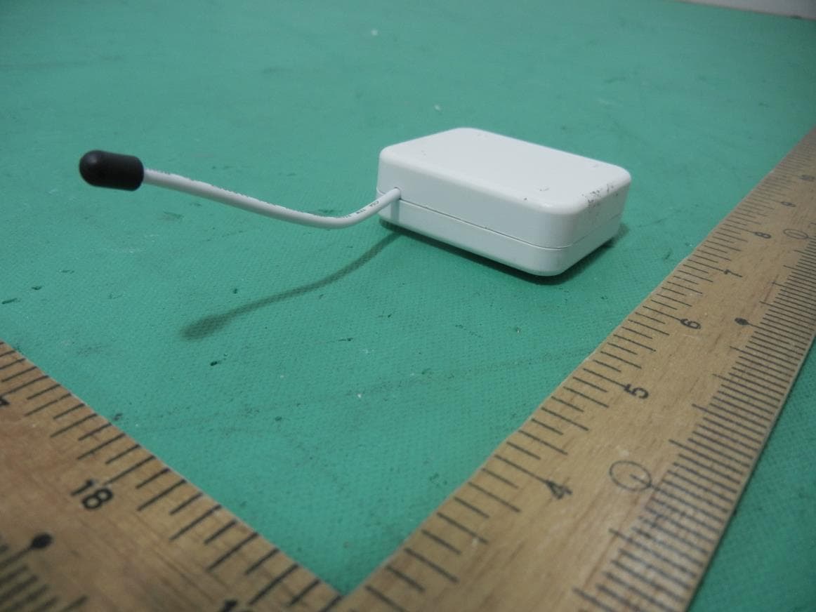
Click to zoom
Application Details
- Equipment Class
- DXX - Part 15 Low Power Communication Device Transmitter
- Date of Grant
- Nov 30, 2015
- Application Purpose
- Original Equipment
- Date of Application
- Nov 30, 2015
- Equipment Note
- Smart Energy In Wall Meter
- Frequency Range
- 908.40000000 - 916.00000000
- Country
- Taiwan
Documents & Files
Document Text
Text extracted from the exhibit documents filed with the FCC. Open a document above to read the original.
Users Manual
PAB01 Smart Energy In Wall Meter Fig 1. Assembling Fig 2. Assembling This dual meter module is a transceiver which is a Z-WaveTM enabled device and is fully compatible with any Z-WaveTM enabled network. Mini size design let the module can easily hide itself into the electricity distribution box and that will be good for the house decoration. This dual meter module is able to detect Instant power wattage (13800W/230Vac)(60 Amperes) of connected light or appliances. Adding to Z-Wave TM Network In the front casing, there is an on/off button with LED indicator below which is used to carry out inclusion, exclusion, reset or association. After being excluded, its LED flashes on and off alternately and repeatedly at 2-second intervals. It implies that it has not been assigned a node ID and cannot work with Z-Wave enabled devices. Auto Inclusion The function of auto inclusion will be executed as long as the meter does not have Node ID and just connect the meter to main power. When first power is applied, its LED flashes on and off alternately and repeatedly at 0.5 second intervals. It implies that it is in leaning mode now. Note: Auto inclusion timeout is 2 minute during which the node information of explore frame will be emitted once every 5 seconds. Unlike “inclusion” function as shown in the table below, the execution of auto inclusion is free from pressing the On/Off button on the meter. The table below lists an operation summary of basic Z-Wave functions. Please refer to the instructions for your Z-WaveTM Certificated Primary Controller to access the Setup function, and to include/exclude/associate devices FunctionDescriptionLED Indication No node IDThe Z-Wave Controller does not allocate2-second on, 2-second off a node ID to the meter. Inclusion1.Have Z-Wave Controller entered inclusion mode. One press one flash 2. Pressing INCLUDE_BUTTON three times within 2 seconds will enter inclusion mode. Exclusion1.Have Z-Wave Controller entered exclusion mode. One press one flash 2.Pressing INCLUDE_BUTTON three times within 2 seconds will enter exclusion mode. Node ID has been excluded.2-second on, 2-second off Reset1.Pressing INCLUDE_BUTTON three times within 2 seconds will enter inclusion mode. One press one flash 2.Within 1 second, press and hold INCLUDE_BUTTON button again for 5 seconds until LED is off. 3.IDs are excluded. Association 1. Have Z-Wave Controller entered association mode. Or Pressing INCLUDE_BUTTON three times within 2 seconds will enter association mode One press one flash 2. There are 3 groups for the meter ※ Including a node ID allocated by Z-Wave Controller means inclusion. Excluding a node ID allocated by Z-Wave Controller means exclusion. ※ Failed or success in including/excluding the node ID can be viewed from the Z-Wave Controller. LED Indication To distinguish what mode the meter is in, view from the LED for identification. State TypeLED Indication No node IDUnder normal operation, when the meter has not been allocated a node ID, the LED flashes on and off alternately at 2 seconds intervals. LearningWhen PAB01 is in learning mode, LED flashes on and off alternately and repeatedly at 0.5 second intervals. Choosing a Suitable Location 1.Do not locate the meter facing direct sunlight, humid or dusty place. 2.The suitable ambient temperature for the Switch is 0°C~40°C. 3.Do not locate the meter where exists combustible substances or any source of heat, e.g. fires, radiators, boiler etc. 4.After putting it into use, the body of meter will become a little bit hot of which phenomenon is normal. Installation 1.Put the in wall switch into a wall box and connect the AC power wire L,N to PAB01 connector L, N. 2.The black wire of current sensor, CT1 or CT2, should connected to the negative terminal of PAB01,CT1- or CT2-. Another wire should connected to the plus terminal of PAB01,CT1+ or CT1+. 3.There is a clasp on the side of the current sensor, it can lock or unlock the clamp. It is convenient to circle the already connected cable. Programming , 1.Z-Wave’s Groups (Association Command Class Version 2) The meter can be set to send reports to associated Z-Wave devices. It supports 3 association groups which every group has one node support. Group1~Group3 support METER_REPORT_COMMAND_V3 For group 1, the Switch will report (1) The sum of instant Power Consumption (Watt) read from CT1 and CT2 (2) The sum of accumulated Power Consumption (KWh) read from CT1 and CT2. For group 2, the Switch will report (1) Instant Power Consumption (Watt) read from CT1 (2) Accumulated Power Consumption (KWh) read from CT1. For group 3, the Switch will report (1) Instant Power Consumption (Watt) read from CT2 (2) Accumulated Power Consumption (KWh) read from CT2. 2-1 Auto report to Grouping 1 ~3 (Maximum Node 1 per Group) 2-1-1 Instant Power Consumption vary over 5% report When the instant power consumption read from CT1 or CT2 vary over 5%, it will send Meter report to the nodes of Group 2-2 Response to Meter Get Command The Switch will report its (1) instant Power Consumption (Watt) or (2) accumulated power consumption(KWH) or (3) AC input Voltage (V) or (4) AC load current ( I ) (5) load power factor (PF) to Z-Wave Controller after receive the Meter Get Command from Z-Wave Controller. 2-2-1 Instant Power Consumption (Watt) When receiving Meter Get Command, it will report Meter Report Command to the node asked. Meter Get Command: [Command Class Meter, Meter Get, Scale =0x02(W)] Meter Report Command: [Command Class Meter , Meter Report , scale(bit 2) +Rate Type +Meter Type , Precision + Scale(bit 1,0)+ Size , Meter Value 1 , Meter Value 2 , Meter Value 3 , Meter Value 4] Rate Type = 0x01 Meter Type = 0x01 Precision = 1 Scale = 0x02(W) Meter Report Command: [Command Class Meter,Meter Report,scale(bit 2) +Rate Type +Meter Type,Precision + Scale(bit 1,0)+ Size,Meter Value 1,Meter Value 2,Meter Value 3,Meter Value 4] Size = 4 Bytes (Meter Value) Meter Value 1 = (W) MSB Meter Value 2 = (W) Meter Value 3 = (W) M…
Text truncated - open the document above for the full version.
External Photos
CERPASS TECHNOLOGY CORP. Report No.: 1510217 Cerpass Technology Corp. Issued Date : Nov. 11, 2015 Page No. : 1 of 3 Photographs of EUT
ID Label/Location Info
Label & Location
Internal Photos
CERPASS TECHNOLOGY CORP. Report No.: 1510217 Cerpass Technology Corp. Issued Date : Nov. 11, 2015 Page No. : 2 of 3 CERPASS TECHNOLOGY CORP. Report No.: 1510217 Cerpass Technology Corp. Issued Date : Nov. 11, 2015 Page No. : 3 of 3
Test Report
CERPASS TECHNOLOGY CORP. Report No.: TEFC1510217 Cerpass Technology Corp.Issued date:Nov. 18, 2015 Tel:886-3-3226-888 Fax:886-3-3226-881Page No.:1of38 FCC ID:RHHPAB01 RADIO TEST REPORT Applicant:Philio Technology Corporation Address: 8F., No.653-2, Zhongzheng Rd., Xinzhuang Dist., New Taipei City 24257,Taiwan(R.O.C) Equipment:Smart Energy In Wall Meter Model No.:PAB01-2 Trade Name :Philio FCC ID:RHHPAB01 I HEREBY CERTIFY THAT : The sample was received on Nov. 03, 2015 and the testing was carried out onNov. 05 2015 at Cerpass Technology Corp. The test result refers exclusively to the test presented test model / sample. Without written approval of Cerpass Technology Corp., the test report shall not be reproduced except in full. Approved by:Tested by: Steven Wang Manager Spree Yei Engineer Laboratory Accreditation: Cerpass Technology Corporation Test Laboratory Cerpass Technology(SuZhou) Co., Ltd. CERPASS TECHNOLOGY CORP. Report No.: TEFC1510217 Cerpass Technology Corp.Issued date:Nov. 18, 2015 Tel:886-3-3226-888 Fax:886-3-3226-881Page No.:2of38 FCC ID:RHHPAB01 Contents 1.Summary of Test Procedure and Test Results.................................................................................4 1.1.Applicable Standards .................................................................................................................4 2.Test Configuration of Equipment under Test ...................................................................................5 2.1.General Description of EUT .......................................................................................................5 2.2.Carrier Frequency of Channels ..................................................................................................5 2.3.Test Mode and Test Software.....................................................................................................5 2.4.Description of Test System.........................................................................................................5 2.5.General Information of Test........................................................................................................6 3.Test Equipment and Ancillaries Used for Tests ...............................................................................7 4.Test of Conducted Emission..............................................................................................................8 4.1.Test Limit ....................................................................................................................................8 4.2.Test Procedures .........................................................................................................................8 4.3.Typical Test Setup ......................................................................................................................9 4.4.Test Result and Data ................................................................................................................10 4.5.Test Photographs .....................................................................................................................14 5.Test of Radiated Emission ...............................................................................................................15 5.1.Test Limit ..................................................................................................................................15 5.2.Test Procedures .......................................................................................................................15 5.3.Typical Test Setup Layout of Radiated Emission .....................................................................16 5.4.Test Result and Data ................................................................................................................17 5.5.Test Photographs (30MHz ~ 1GHz) .........................................................................................37 5.6.Test Photographs (1GHz ~ 10GHz) .........................................................................................38 CERPASS TECHNOLOGY CORP. Report No.: TEFC1510217 Cerpass Technology Corp.Issued date:Nov. 18, 2015 Tel:886-3-3226-888 Fax:886-3-3226-881Page No.:3of38 FCC ID:RHHPAB01 History of this test report ORIGINAL. Additional attachment as following record: Attachment No.Issue DateDescription TEFC1510217Nov. 18, 2015Original. CERPASS TECHNOLOGY CORP. Report No.: TEFC1510217 Cerpass Technology Corp.Issued date:Nov. 18, 2015 Tel:886-3-3226-888 Fax:886-3-3226-881Page No.:4of38 FCC ID:RHHPAB01 1. Summary of Test Procedure and Test Results 1.1. Applicable Standards ANSI C63.4: 2009 FCC Rules and Regulations Part 15 Subpart C§15.249 FCC RuleDescription of TestResult 15.207Conducted EmissionPass 15.209 15.249 Radiated EmissionPass CERPASS TECHNOLOGY CORP. Report No.: TEFC1510217 Cerpass Technology Corp.Issued date:Nov. 18, 2015 Tel:886-3-3226-888 Fax:886-3-3226-881Page No.:5of38 FCC ID:RHHPAB01 2. Test Configuration of Equipment under Test 2.1. General Description of EUT Modulation TypeGFSK Operating Frequency908.4MHz, 916MHz Antenna Type/ gainMonopole Antenna/ 0dBi 2.2. Carrier Frequency of Channels ChannelFrequency(MHz)ChannelFrequency(MHz) *1908.4*2916 Note: Channels remarked“*”are selected to perform test. 2.3. Test Mode and Test Software a. During testing, the interface cables and equipment positions were varied according to ANSI C63.4. b. The complete test system included EUT for RF test. 2.4. Description of Test System No supporting system during the test. CERPASS TECHNOLOGY CORP. Report No.: TEFC1510217 Cerpass Technology Corp.Issued date:Nov. 18, 2015 Tel:886-3-3226-888 Fax:886-3-3226-881Page No.:6of38 FCC ID:RHHPAB01 2.5. General Information of Test Test Site Cerpass Technology Corporation Test Laboratory Address: No.10, Ln. 2, Lianfu St., Luzhu Dist., Taoyuan City 33848, Taiwan (R.O.C.) Tel:+886-3-3226-888 Fax:+886-3-3226-881 Address: No.68-1, Shihbachongsi, Shihding Township…
Text truncated - open the document above for the full version.
Test Setup Photos
CERPASS TECHNOLOGY CORP. Report No.: TEFC1510217 Cerpass Technology Corp.Issued date:Nov. 18, 2015 Tel:886-3-3226-888 Fax:886-3-3226-881Page No.:14of38 FCC ID:RHHPAB01 4.5. Test Photographs Front View Rear View CERPASS TECHNOLOGY CORP. Report No.: TEFC1510217 Cerpass Technology Corp.Issued date:Nov. 18, 2015 Tel:886-3-3226-888 Fax:886-3-3226-881Page No.:37of38 FCC ID:RHHPAB01 5.5. Test Photographs (30MHz ~ 1GHz) Front View Rear View CERPASS TECHNOLOGY CORP. Report No.: TEFC1510217 Cerpass Technology Corp.Issued date:Nov. 18, 2015 Tel:886-3-3226-888 Fax:886-3-3226-881Page No.:38of38 FCC ID:RHHPAB01 5.6. Test Photographs (1GHz ~ 10GHz) Front View Rear View
Contact Information
Applicant
JAMES HUANG(CEO)
Technical Contact
Philio Technology CorporationJAMES HUANG
[email protected]886-229088952
8F., NO. 653-2, ZHONGZHENG RD., · Taiwan
Non-Technical Contact
Cerpass Technology Corp.Delia Feng
[email protected]886-3-3226-888
Test Firm
Cerpass Technology Corporation Test LaboratoryBen Wang
Technical Specifications
| # | Rule Parts | Frequency Range | Power Output |
|---|---|---|---|
| 1 | 15C | 908.4 MHz - 916 MHz | - |
Other Applications from Philio Technology Corporation
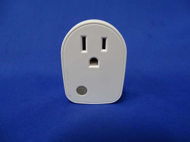
RHHPAN15
May 13, 2015Smart energy plug in switch
Equipment Class
DXX - Part 15 Low Power Communication Device Transmitter
RHHPSR04
May 05, 2015Smart Color Button
Equipment Class
DXX - Part 15 Low Power Communication Device Transmitter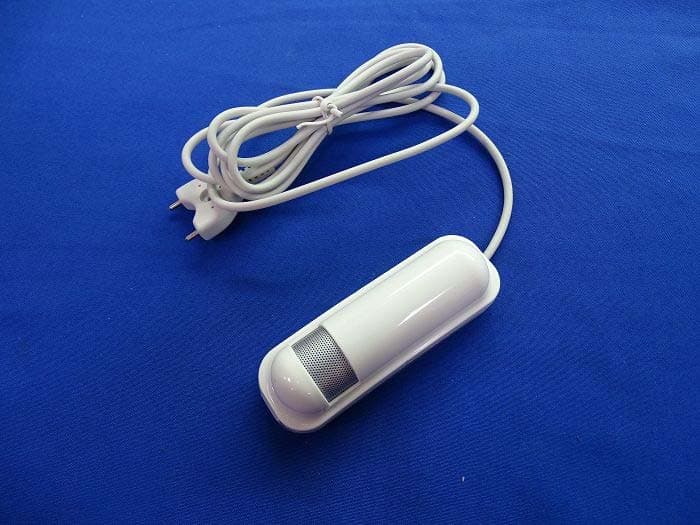
RHHPAT02
Apr 01, 2015Flood Multi Sensor
Equipment Class
DXX - Part 15 Low Power Communication Device Transmitter
RHHPSG01
Jan 27, 2015Z-Wave Smoke Sensor
Equipment Class
DXX - Part 15 Low Power Communication Device Transmitter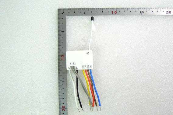
RHHPAN07
Oct 23, 2014In Wall Dual relay(2 way) switch module
Equipment Class
DXX - Part 15 Low Power Communication Device Transmitter