RHHPAT02Flood Multi Sensor
Philio Technology Corporation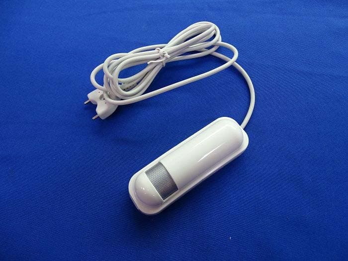
Click to zoom
Application Details
- Equipment Class
- DXX - Part 15 Low Power Communication Device Transmitter
- Date of Grant
- Apr 01, 2015
- Application Purpose
- Original Equipment
- Date of Application
- Apr 01, 2015
- Equipment Note
- Flood Multi Sensor
- Frequency Range
- 908.40000000 - 916.00000000
- Country
- Taiwan
Documents & Files
Document Text
Text extracted from the exhibit documents filed with the FCC. Open a document above to read the original.
Users Manual
Flood Multisensor PAT02-A/B/C The flood multisensor PAT02 has flood, temperature and humidity, 3 sensors function in one, based on Z-Wave TM technology. It is the Z-Wave TM plus product, it support the security, OTA... Those newest features of the Z-Wave TM technology. Z-Wave TM is a wireless communication protocol designed for home automation, specifically to remotely control applications in residential and light commercial environments. The technology uses a low-power RF radio embedded or retrofitted into home electronics devices and systems, such as lighting, home access control, entertainment systems and household appliances. This product can be included and operated in any Z-Wave TM network with other Z-Wave TM certified devices from other manufacturers and/or other applications. All non-battery operated nodes within the network will act as repeaters regardless of vendor to increase reliability of the network. The device adopt the Z-Wave TM 500 series chip, when your Z-Wave TM network system is all made by Z-Wave TM 500 series devices. The network system will have the advantages as below. •Concurrent multi-channel support reduces external interference. •Better RF range, improve about 10 meters in indoor. •Support 100 Kbps transmit speed, speed up communication. Function Compare A/B/C FloodTemperatureHumidity PAT02-AVVV PAT02-BVV PAT02-CV Add to/Remove from Z-Wave TM Network There are one tamper keys in the back side of the device, It can add, remove, reset or association from the Z-Wave TM network. In the first time, add the device into the Z-Wave TM network. First, make sure the primary controller is in the add mode. And then power on the device, just take out the insulation Mylar in the back side of the device. The device will auto start the NWI (Network Wide Inclusion) mode. And it should be included in 5 seconds. You will see the LED light ON one second. Notice: Including a node ID allocated by Z-Wave TM Controller means “Add” or “Inclusion”. Excluding a node ID allocated by Z-Wave TM Controller means “Remove” or “Exclusion”. 1 Function Description Add 1.Have Z-Wave TM Controller entered inclusion mode. 2.Pressing the tamper key three times within 1.5 seconds to enter the inclusion mode. 3.After add successful, the device will wake to receive the setting command from Z-Wave TM Controller about 20 seconds. Remove 1.Have Z-Wave TM Controller entered exclusion mode. 2.Pressing tamper key three times within 1.5 seconds to enter the exclusion mode. Node ID has been excluded. Reset Notice: Use this procedure only in the event that the primary controller is lost or otherwise inoperable. 1.Pressing tamper key four times within 1.5 seconds and do not release the tamper key in the 4 th pressed, and the LED will light ON. 2.After 3 seconds the LED will turn OFF, after that within 2 seconds, release the tamper key. If successful, the LED will light ON one second. Otherwise, the LED will flash once. 3.IDs are excluded and all settings will reset to factory default. Association 1.Have Z-Wave TM Controller entered association mode. 2.Pressing tamper key three times within 1.5 seconds to enter the association mode. Note: The device support 2 groups. The group 1 is for receiving the report message, like triggered event, temperature, humidity etc. The group 2 is for the light control, the device will send the “Basic Set” command to this group. And each group support 8 nodes maximum. •Failed or success in add/remove the node ID can be viewed from Z-Wave TM Controller. Notice 1: Always RESET a Z-Wave TM device before trying to add it to a Z-Wave TM network Notice 2: When the device into NWI mode, the sensor functionality will useless. The NWI mode will timeout after 30 seconds. You can press the tamper key 3 times to abort the NWI mode. Z-Wave TM Notification After the device adding to the network, it will wake-up once per day in default. When it wake-up it will broadcast the “Wake Up Notification” message to the network, and wake-up 10 seconds for receive the setting commands. The wake-up interval minimum setting is 30 minutes, and maximum setting is 120 hours. And the interval step is 30 minutes. Press the tamper key once. The device will wake-up 10 seconds. Z-Wave TM Message Report When the flood triggered the device will report the trigger event and also report the battery status, temperature and humidity. In default the device will using Notification Report to represent the trigger event, it can be changed to Sensor Binary Report by setting the configuration NO. 7 Bit4 to 1. * Flood Report: When the flood triggered, the device will unsolicited to send the report to the nodes in the group 1. Notification Report (V4) Notification Type: Water Alarm (0x05) Event: Water Leak detected, Unknown Location (0x02) 2 Sensor Binary Report (V2) Sensor Type: Water (0x06) Sensor Value: 0xFF And after the flood trigger clear, the device will unsolicited to send the report to the nodes in the group 1. Notification Report (V4) Notification Type: Water Alarm (0x05) Event: 0x00 Sensor Binary Report (V2) Sensor Type: Water (0x06) Sensor Value: 0x00 * Tamper Report: The tamper key pressed over 5 seconds. The device will into the alarm state. In that state, if the tamper key be released, the device will unsolicited to send the report to the nodes in the group 1. Notification Report (V4) Notification Type: Home Security (0x07) Event: Tampering. Product covering removed (0x03) Sensor Binary Report (V2) Sensor Type: Tamper (0x08) Sensor Value: 0xFF * Temperature Report: When the flood triggered or the temperature differential over 1 Fahrenheit (in default), the device will unsolicited to send the “Sensor Multilevel Report” to the nodes in the group 1. Sensor Type: Temperature (0x01) Note: To disable send temperature report after the flood triggered, please setting the configuration N0.5 bit5 to 1. *** Temperature differential report *** This function default is enabled, to disable this function by setting the configurat…
Text truncated - open the document above for the full version.
External Photos
Report No.: 1530189R-RFUSP15V00 Page : 1 of 24 Attachment 2 : EUT Detailed Photographs (1) EUT Photo (M/N: PAT02-2A) (2) EUT Photo Report No.: 1530189R-RFUSP15V00 Page : 2 of 24 (3) EUT Photo (M/N: PAT02-2B) (4) EUT Photo Report No.: 1530189R-RFUSP15V00 Page : 3 of 24 (5) EUT Photo (M/N: PAT02-2C) (6) EUT Photo
ID Label/Location Info
Philio Technology Corporation FCC ID.: RHHPAT02 8F.,No.653-2,Zhongzheng Rd., Xinzhuang Dist., New Taipei City 24257,Taiwan(R.O.C)Tel : 886-229088952 The FCC ID will be placed on the equipment as shown in the photograph below.
ID Label/Location Info
Philio Technology Corporation FCC ID.: RHHPAT02 8F.,No.653-2,Zhongzheng Rd., Xinzhuang Dist., New Taipei City 24257,Taiwan(R.O.C)Tel : 886-229088952 FCC ID Label M/N: PAT02-2A M/N: PAT02-2B M/N: PAT02-2C
Internal Photos
Report No.: 1530189R-RFUSP15V00 Page : 4 of 24 (7) EUT Photo (M/N: PAT02-2A) (8) EUT Photo Report No.: 1530189R-RFUSP15V00 Page : 5 of 24 (9) EUT Photo (10) EUT Photo Report No.: 1530189R-RFUSP15V00 Page : 6 of 24 (11) EUT Photo (12) EUT Photo Antenna Report No.: 1530189R-RFUSP15V00 Page : 7 of 24 (13) EUT Photo (14) EUT Photo Report No.: 1530189R-RFUSP15V00 Page : 8 of 24 (15) EUT Photo (16) EUT Photo Report No.: 1530189R-RFUSP15V00 Page : 9 of 24 (17) EUT Photo (18) EUT Photo Report No.: 1530189R-RFUSP15V00 Page : 10 of 24 (19) EUT Photo (20) EUT Photo Report No.: 1530189R-RFUSP15V00 Page : 11 of 24 (21) EUT Photo (22) EUT Photo (M/N: PAT02-2B) Report No.: 1530189R-RFUSP15V00 Page : 12 of 24 (23) EUT Photo (24) EUT Photo Report No.: 1530189R-RFUSP15V00 Page : 13 of 24 (25) EUT Photo (26) EUT Photo Report No.: 1530189R-RFUSP15V00 Page : 14 of 24 (27) EUT Photo (28) EUT Photo Antenna Report No.: 1530189R-RFUSP15V00 Page : 15 of 24 (29) EUT Photo (30) EUT Photo Report No.: 1530189R-RFUSP15V00 Page : 16 of 24 (31) EUT Photo (32) EUT Photo Report No.: 1530189R-RFUSP15V00 Page : 17 of 24 (33) EUT Photo (34) EUT Photo Report No.: 1530189R-RFUSP15V00 Page : 18 of 24 (35) EUT Photo (36) EUT Photo (M/N: PAT02-2C) Report No.: 1530189R-RFUSP15V00 Page : 19 of 24 (37) EUT Photo (38) EUT Photo Report No.: 1530189R-RFUSP15V00 Page : 20 of 24 (39) EUT Photo (40) EUT Photo Report No.: 1530189R-RFUSP15V00 Page : 21 of 24 (41) EUT Photo (42) EUT Photo Antenna Report No.: 1530189R-RFUSP15V00 Page : 22 of 24 (43) EUT Photo (44) EUT Photo Report No.: 1530189R-RFUSP15V00 Page : 23 of 24 (45) EUT Photo (46) EUT Photo Report No.: 1530189R-RFUSP15V00 Page : 24 of 24 (47) EUT Photo (48) EUT Photo
RF Exposure Info
Report No. 1530189R-RFUSP15V00 Page: 1 of 1 Version: 1.0 RF Exposure Statement 1. Standard Applicable According to 1.1307 (b)(1), systems operating under the provisions of this section shall be operated in a manner that ensure that the public is not exposed to radio frequency energy level in excess of the Commission’s guideline. 2. Measurement Result: According to Section 4.3.1 of KDB 447498 D01 Mobile Portable RF Exposure v05, operation frequency = 908.4MHz and antenna separation distance = 5mm Field strength is converted into Pout (dBm) Radiated Power @3m Distance Antenna Gain Maximum conducted output power (dBuV/m) (m) (dBi) (dBm) 91.194 3 0 ‐4.03 Note: The Device max peak output power = -4.03dBm, Equivalent to 0.395mW 075.09084.0* 5 395.0 mW 0.075 ≦3.0, The SAR/MPE measurement is not necessary. G Ed P 30 )( 2
Test Report
Report No. 1530189R-RFUSP15V00 Page : 1 of 31 FCC Test Report Product Name Flood Multi sensor Model No. PAT02-2A,PAT02-2B,PAT02-2C FCC ID. RHHPAT02 Applicant Philio Technology Corporation Address 8F.,No.653-2,Zhongzheng Rd., Xinzhuang Dist., New Taipei City 24257,Taiwan(R.O.C) Date of Receipt Mar. 10, 2015 Issue Date Mar. 24, 2015 Report No. 1530189R-RFUSP15V00 Report Version V1.0 The test results relate only to the samples tested. The test results shown in the test report are traceable to the national/international standard through the calibration of the equipment and evaluated measurement uncertainty herein. This report must not be used to claim product endorsement by TAF or any agency of the government. The test report shall not be reproduced without the written approval of QuieTek Corporation. Report No. 1530189R-RFUSP15V00 Page : 2 of 31 Test Report Issued Date: Mar. 24, 2015 Report No.: 1530189R-RFUSP15V00 Product Name Flood Multi sensor Applicant Philio Technology Corporation Address 8F.,No.653-2,Zhongzheng Rd., Xinzhuang Dist., New Taipei City 24257,Taiwan(R.O.C) Manufacturer Philio Technology Corporation Model No. PAT02-2A,PAT02-2B,PAT02-2C FCC ID. RHHPAT02 EUT Rated Voltage DC 3V (Power by battery) EUT Test Voltage DC 3V (Power by battery) Trade Name Applicable Standard FCC CFR Title 47 Part 15 Subpart C: 2014 ANSI C63.4: 2014, ANSI C63.10: 2013 Test Result Complied Documented By : (Senior Adm. Specialist / Leven Huang ) Tested By : ( Engineer / Jerry Tsai ) Approved By : ( Director / Vincent Lin ) Report No. 1530189R-RFUSP15V00 Page : 3 of 31 TABLE OF CONTENTS Description Page 1. GENERAL INFORMATION ................................................................................................................ 4 1.1. EUT Description ...................................................................................................................................... 4 1.2. Operation Description .............................................................................................................................. 5 1.3. Tested System Details .............................................................................................................................. 6 1.4. Configuration of Test System ................................................................................................................... 6 1.5. EUT Exercise Software ............................................................................................................................ 6 1.6. Test Facility .............................................................................................................................................. 7 2. Conducted Emission .............................................................................................................................. 8 2.1. Test Equipment ........................................................................................................................................ 8 2.2. Test Setup ................................................................................................................................................. 8 2.3. Limits ....................................................................................................................................................... 9 2.4. Test Procedure .......................................................................................................................................... 9 2.5. Uncertainty ............................................................................................................................................... 9 2.6. Test Result of Conducted Emission ....................................................................................................... 10 3. Radiated Emission ............................................................................................................................... 11 3.1. Test Equipment ...................................................................................................................................... 11 3.2. Test Setup ............................................................................................................................................... 12 3.3. Limits ..................................................................................................................................................... 13 3.4. Test Procedure ........................................................................................................................................ 14 3.5. Uncertainty ............................................................................................................................................. 14 3.6. Test Result of Radiated Emission .......................................................................................................... 15 4. Band Edge ............................................................................................................................................. 24 4.1. Test Equipment ...................................................................................................................................... 24 4.2. Test Setup ............................................................................................................................................... 25 4.3. Limit ....................................................................................................................................................... 26 4.4. Test Procedure ........................................................................................................................................ 26 4.5. Uncertainty ............................................................................................................................................. 26 4.6. Test Result of Band Edge ............................................................................................…
Text truncated - open the document above for the full version.
Test Setup Photos
Report No.: 1530189R-RFUSP15V00 Page : 1 of 2 Attachment 1: EUT Test Setup Photographs Front View of Radiated Test Back View of Radiated Test Report No.: 1530189R-RFUSP15V00 Page : 2 of 2 Front View of Radiated Test (Horn) Back View of Radiated Test (Horn)
Contact Information
Applicant
JAMES HUANG(CEO)
Test Firm
DEKRA TESTING AND CERTIFICATION CO., LTD. LinKouMirenda Liao
Technical Specifications
| # | Rule Parts | Frequency Range | Power Output |
|---|---|---|---|
| 1 | 15C | 908.4 MHz - 916 MHz | - |
Other Applications from Philio Technology Corporation
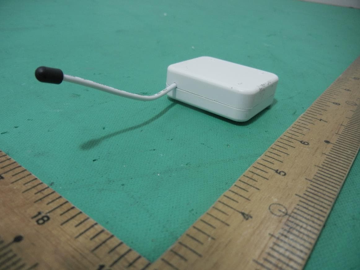
RHHPAB01
Nov 30, 2015Smart Energy In Wall Meter
Equipment Class
DXX - Part 15 Low Power Communication Device Transmitter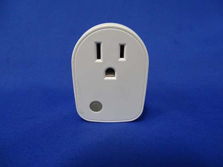
RHHPAN15
May 13, 2015Smart energy plug in switch
Equipment Class
DXX - Part 15 Low Power Communication Device Transmitter
RHHPSR04
May 05, 2015Smart Color Button
Equipment Class
DXX - Part 15 Low Power Communication Device Transmitter
RHHPSG01
Jan 27, 2015Z-Wave Smoke Sensor
Equipment Class
DXX - Part 15 Low Power Communication Device Transmitter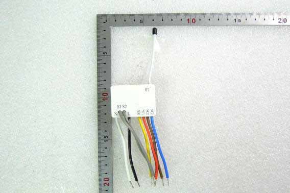
RHHPAN07
Oct 23, 2014In Wall Dual relay(2 way) switch module
Equipment Class
DXX - Part 15 Low Power Communication Device Transmitter