RHHPSR04Smart Color Button
Philio Technology Corporation
Click to zoom
Application Details
- Equipment Class
- DXX - Part 15 Low Power Communication Device Transmitter
- Date of Grant
- May 05, 2015
- Application Purpose
- Original Equipment
- Date of Application
- May 05, 2015
- Equipment Note
- Smart Color Button
- Frequency Range
- 908.40000000 - 916.00000000
- Country
- Taiwan
Documents & Files
Document Text
Text extracted from the exhibit documents filed with the FCC. Open a document above to read the original.
Users Manual
1 PSR04 Smart Color Button This round device is a flexible and multi functions button switch. It is able to switch the appliances on/off or activate the scenes and macros which are preset already. The rotation sensor make it possible to ad just the percentage of dimmer or thermostat. It can also work as a timer. The wel l designed wall bracket and magnetic back let the switch can be fixed on the wa ll, Plus TM enabled device and is fully compatible with any Z-Wave TM enabled network. Note: Please provide a 5 DVC voltage to wake the device u p before the first using. The rotation function and timer functions work only when the device is fitted upright or stick on the wall or th e device will only work as an on/off switch when fitted horizonta l. LED indicators 1. LED type and locations There are two sets of LED embedded in the device. A. Set 1: Two full color LED lights round the devic e. B. Set 2: One red LED under the arrowhead on at the front side. 2. Low battery The device will enter low battery mode when the bat tery power is under 20%. The red LED flashes three times every one minu te. 3. NWI Auto Inclusion The red LED will flash quickly for 30 seconds when device entering in NWI mode. 4. Percentage adjustment mode The full color LED will turn from green to red acco rding to the percentage from 0% to 100%. (shown in Fig 3.) 5. Timer mode A. The red LED will flash once when device entering /exiting the timer mode.. B. The full color LED will flash once every 10 seco nds and the color will depend on time table (shown in Fig 3.) Red LED Full Color LED 2 Full Color LED 1 Touch Button Fig. 1 Assembling 2 C. The full color LED will flash once with pink eve ry 10 second when countdown from 30. D. The full color LED will flash with pink light ev ery 1 second when countdown from 5. E. The red LED will flash 6 times with white when t ime’s up. Z-Wave Network Setting Up There is a touch button on the front side. The butt on carry out inclusion, exclusion and reset to default. 1. Include: Pointing the arrowhead to area A first (shown in Fig. 2). Pressing the button three times within 1.5 seconds. The red LED will light up for 1 second if succeed. 2. Exclude: Pointing the arrowhead to area A first (shown in Fig. 2). Pressing the button three times within 1.5 seconds. 3. Reset to default: Pointing the arrowhead to area A first ((shown in Fig. 2)). Pressing button four times within 2 seconds and hol d at fourth. The red LED will light for 3 seconds, release the button within 2 seconds while the LED go out. The LED will flash for 1 second if reset su cceed, or LED will flash once . Build-in Buzzer 1. Turn light on: Beep once. 2. Turn light off: Long beep once. 3. Timer: A. Beep once for setting up the timer. B. Long beep once for stop counting down. C. Beep once every ten seconds for countdown from t hirty. D. Beep once every per second for countdown from fi ve. Four times beep and repeat six times when time’s up. Fig. 2 Control Area Fig. 3 Timer Table A C B D 3 Timer 1. Entering the timer mode: A. Pointing the arrowhead to area A. B. Pressing and hold the button about three to five seconds. The red LED will light then go out. Release the button when the light goes out and the buzzer will sound long beep once. 2. Exit the timer mode: A. Pointing the arrowhead to area A. B. Pressing and hold the button about three to five seconds. The red LED will light then go out. Release the button when the light goes out and the buzzer will sound beep twice. 3. Setting up timer: Pointing the arrowhead to the zone you want to count down (shown in Fig. 3). The countdown will begin af ter you pressing the button and sound beep. Choosing a Suitable Location 1. Do not locate the Switch facing direct sunlight, humid or dusty place. 2. The suitable ambient temperature for the Switch is -10°C~40°C. 3. Do not locate the Switch where exists combustibl e substances or any source of heat, e.g. fires, radiators, boiler etc. Z-Wave’s Groups (Association Command Class Version 2) The Switch can be set to send reports to control as sociated Z-Wave devices. It supports 2 association groups which every group has eight node support. For group 1, the Switch will report event to Z-Wave Controller. Eg. Battery state For group 2, the Switch can control ON/OFF status o f lamps 1. Firmware update over the air (OTA) PSR04 is based on 500 series SoC and supports Firmw are Update Command Class, it can receives the updated firmware image s ent by controller via the Z-wave RF media. It is a helpful and convenient way to improve some function if needed. 2. Command Classes The Switch supports Command Classes including... * COMMAND_CLASS_ZWAVEPLUS_INFO_V2 * COMMAND_CLASS_BATTERY * COMMAND_CLASS_CENTRAL_SCENE_V1 * COMMAND_CLASS_VERSION_V2 * COMMAND_CLASS_MANUFACTURER_SPECIFIC_V2 * COMMAND_CLASS_DEVICE_RESET_LOCALLY * COMMAND_CLASS_ASSOCIATION_V2 * COMMAND_CLASS_WAKE_UP_V2 * COMMAND_CLASS_ASSOCIATION_GRP_INFO * COMMAND_CLASS_POWERLEVEL * COMMAND_CLASS_MULTI_CMD * COMMAND_CLASS_SECURITY * COMMAND_CLASS_MARK * COMMAND_CLASS_BASIC * COMMAND_CLASS_FIRMWARE_UPDATE_MD_V2 * COMMAND_CLASS_CONFIGURATION 4 Troubleshooting Symptom Cause of Failure Recommendation The Switch not working and LED off 1. Battery dead 2. Device break 1. Charging the battery by Micro USB. 2. Don’t open up the Switch and send it for repair. Can not adjust the percentage of dimmer or thermostat The device may not be placed upright. Check if the device is placed upright. The device can not join to Z-Wave network The device may has joined to a network. 1. Exclude the device then include again. Button no response The button will no response when LED is flashing Wait for the LED go out and try again. Specification Operating Voltage 3.7 V (Lithium Polymer Battery) Low Battery Voltage 3.6 V Range Minimum 40 m in door, 100m outdoor line of s ight Operating Temperature -10°C ~ 45°C Frequency Range PSR04-1: 868.40MHz; 869.85MHz(EU) / PSR04-2: 908.40MHz; 916.00MHz(USA/Canada) / PSR04-3: 922.5M…
Text truncated - open the document above for the full version.
External Photos
Page 1 CONSTRUCTION PHOTOS OF EUT Page 2
ID Label/Location Info
Label location
Internal Photos
Page 3 Page 4 Page 5 Page 6
Operational Description
FCC ID: RHHPSR04 Report No.: RF150415C02 OPERATIONAL DESCRIPTION The transmitter of the EUT (Smart Color Button) is powered from 5Vdc host equipment or 3.7Vdc battery. The antenna is Monopole antenna without antenna connector. For more detailed instruction, please take a look at the user’s manual.
Test Report
Report No.: RF150415C02 Page No. 1 / 26 Report Format Version: 6.1.1 FCC Test Report Report No.: RF150415C02 FCC ID: RHHPSR04 Test Model: PSR04-2 Received Date: Apr. 15, 2015 Test Date: Apr. 27, 2015 Issued Date: Apr. 29, 2015 Applicant: Philio Technology Corporation Address: 8F., No. 653-2, Zhongzheng Rd., Xinzhuang Dist., New Taipei City 24257, Ta i w a n ( R . O . C ) Issued By: Bureau Veritas Consumer Products Services (H.K.) Ltd., Taoyuan Branch Lab Address: No. 47-2, 14th Ling, Chia Pau Vil., Lin Kou Dist., New Taipei City, Taiwan Test Location: No. 19, Hwa Ya 2nd Rd., Wen Hwa Vil., Kwei Shan Dist., Taoyuan City 33383, TAIWAN (R.O.C.) This report is for your exclusive use. Any copying or replication of this report to or for any other person or entity, or use of our name or trademark, is permitted only with our prior written permission. This report sets forth our findings solely with respect to the test samples identified herein. The results set forth in this report are not indicative or representative of the quality or characteristics of the lot from which a test sample was taken or any similar or identical product unless specifically and expressly noted. Our report includes all of the tests requested by you and the results thereof based upon the information that you provided to us. You have 60 days from date of issuance of this report to notify us of any material error or omission caused by our negligence, provided, however, that such notice shall be in writing and shall specifically address the issue you wish to raise. A failure to raise such issue within the prescribed time shall constitute your unqualified acceptance of the completeness of this report, the tests conducted and the correctness of the report contents. Unless specific mention, the uncertainty of measurement has been explicitly taken into account to declare the compliance or non-compliance to the specification. This report should not be used by the client to claim product certification, approval, or endorsement by TAF or any government agencies. Report No.: RF150415C02 Page No. 2 / 26 Report Format Version: 6.1.1 Table of Contents Release Control Record .................................................................................................................................. 3 1 Certificate of Conformity ...................................................................................................................... 4 2 Summary of Test Results ..................................................................................................................... 5 2.1 Measurement Uncertainty ................................................................................................................... 5 2.2 Modification Record ............................................................................................................................ 5 3 General Information .............................................................................................................................. 6 3.1 General Description of EUT ................................................................................................................ 6 3.2 Description of Test Modes ................................................................................................................... 6 3.2.1 Test Mode Applicability and Tested Channel Detail ............................................................................. 7 3.3 Description of Support Units ............................................................................................................... 9 3.3.1 Configuration of System under Test .................................................................................................... 9 3.4 General Description of Applied Standards ........................................................................................ 10 4 Test Types and Results ....................................................................................................................... 11 4.1 Radiated Emission and Bandedge Measurement .............................................................................. 11 4.1.1 Limits of Radiated Emission and Bandedge Measurement ............................................................... 11 4.1.2 Test Instruments ................................................................................................................................ 12 4.1.3 Test Procedures ................................................................................................................................. 13 4.1.4 Deviation from Test Standard ............................................................................................................ 13 4.1.5 Test Set Up ........................................................................................................................................ 14 4.1.6 EUT Operating Conditions ................................................................................................................. 14 4.1.7 Test Results ....................................................................................................................................... 15 4.2 Conducted Emission Measurement .................................................................................................. 21 4.2.1 Limits of Conducted Emission Measurement .................................................................................... 21 4.2.2 Test Instruments ................................................................................................................................ 21 4.2.3 Test Procedures ................................................................................................................................. 22 4.2.4 Deviation from Test Standard ............................................................................................................ 22 4.2.5 Test Setup .................................…
Text truncated - open the document above for the full version.
Test Setup Photos
1 PHOTOGRAPHS OF THE TEST CONFIGURATION CONDUCTED EMISSION TEST 2 RADIATED EMISSION TEST (Test Mode A) 3 RADIATED EMISSION TEST (Test Mode B)
Contact Information
Applicant
JAMES HUANG(CEO)
Test Firm
Bureau Veritas CPS (H.K.) Ltd., Taoyuan BranchRichard Chen
Technical Specifications
| # | Rule Parts | Frequency Range | Power Output |
|---|---|---|---|
| 1 | 15C | 908.4 MHz - 916 MHz | - |
Other Applications from Philio Technology Corporation
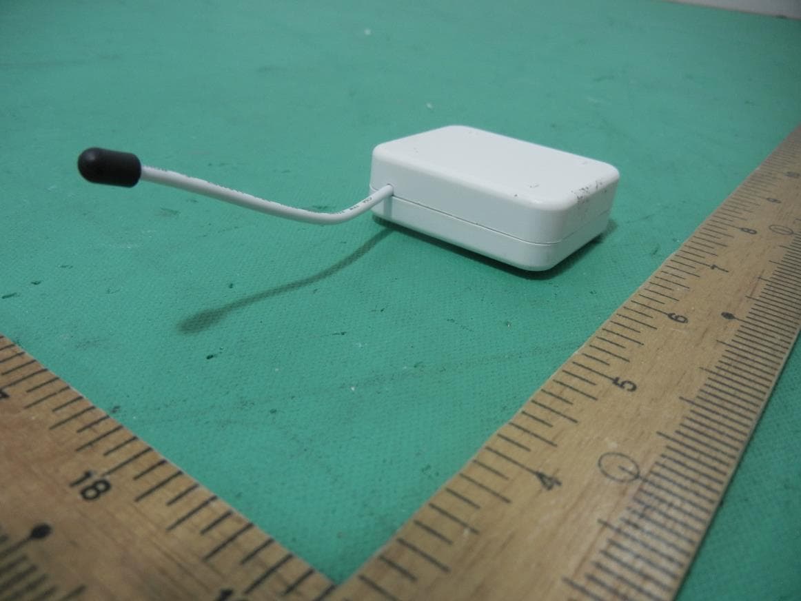
RHHPAB01
Nov 30, 2015Smart Energy In Wall Meter
Equipment Class
DXX - Part 15 Low Power Communication Device Transmitter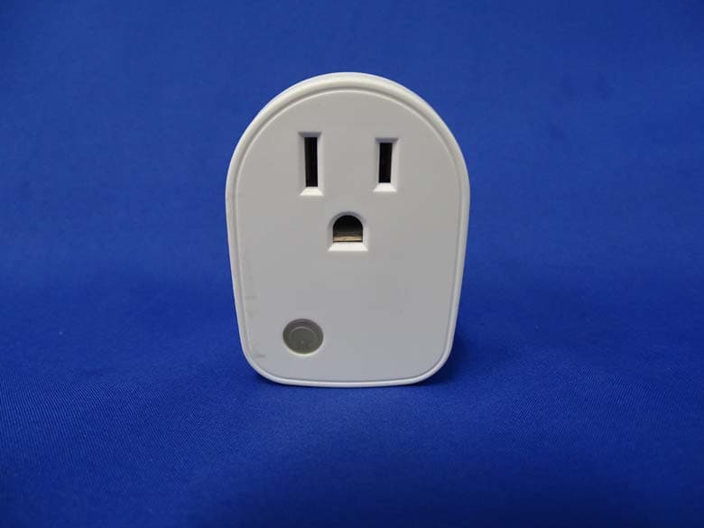
RHHPAN15
May 13, 2015Smart energy plug in switch
Equipment Class
DXX - Part 15 Low Power Communication Device Transmitter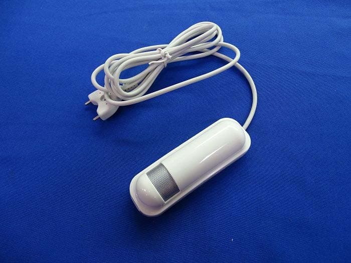
RHHPAT02
Apr 01, 2015Flood Multi Sensor
Equipment Class
DXX - Part 15 Low Power Communication Device Transmitter
RHHPSG01
Jan 27, 2015Z-Wave Smoke Sensor
Equipment Class
DXX - Part 15 Low Power Communication Device Transmitter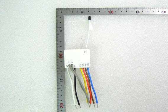
RHHPAN07
Oct 23, 2014In Wall Dual relay(2 way) switch module
Equipment Class
DXX - Part 15 Low Power Communication Device Transmitter