RPARFM3L00Duplicator with RFID System
Riso Kagaku Corporation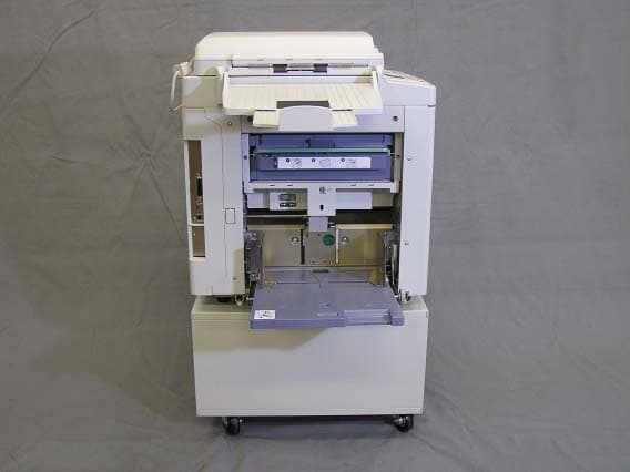
Click to zoom
Application Details
- Equipment Class
- DXT - Part 15 Low Power Transceiver, Rx Verified
- Date of Grant
- Jan 14, 2004
- Application Purpose
- Original Equipment
- Date of Application
- Jan 14, 2004
- Equipment Note
- Duplicator with RFID System
- Frequency Range
- 13.56000000 - 13.56000000
- Company
- Riso Kagaku Corporation
- Country
- Japan
Documents & Files
Document Text
Text extracted from the exhibit documents filed with the FCC. Open a document above to read the original.
Users Manual
1 Riso shall not be responsible for any damage or expense that might result from the use of this manual. As we are constantly improving our products, the machine may differ in some respects from the illustrations used in this manual. Riso shall not be liable for any direct, incidental, or consequential damages of any nature, or losses or expenses resulting from the use of this product or included manuals. is a registered trademark of RISO KAGAKU CORPORATION in Japan and other countries. is a trademark of RISO KAGAKU CORPORATION. - This product contains RFID (Radio Frequency Identification) System. - The information contained in this document is subject to change without notice. For RZ390UI, RZ310UI and RZ220UI Models Only FCC ID:RPARFM3L00 This device complies with Part 15 of the FCC Rules. Operation is subject to the following two conditions: (1) this device may not cause harmful interference, and (2) this device must accept any interference received, including interference that may cause undesired operation. This equipment has been tested and found to comply with the limits for a Class B digital device, pursuant to part 15 of the FCC Rules. These limits are designed to provide reasonable protection against harmful interference in a residential installation. This equipment generates, uses and can radiate radio frequency energy and, if not installed and used in accordance with the instructions, may cause harmful interference to radio communications. However, there is no guarantee that interference will not occur in a particular installation. If this equipment does cause harmful interference to radio or television reception, which can be determined by turning the equipment off and on, the user is encouraged to contact your service representative. EQUIPMENT MODIFICATION CAUTION: Equipment changes or modifications not expressly approved by Riso Kagaku Corporation, the party responsible for FCC compliance, could void the user’s authority to operate the equipment and could create a hazardous condition. For RZ390UI, RZ310UI and RZ220UI Models Only Canada IC:4819A-RFM3L00 Operation is subject to the following two conditions: (1) this device may not cause interference, and (2) this device must accept any interference, including interference that may cause undesired operation of the device. WARNING For RZ370AW, RZ230AW and RZ200AW Models Only This is a Class A product. In a domestic environment this product may cause radio interference in which case the user may be required to take adequate measures. TM Copyright © 2003 RISO KAGAKU CORPORATION 2 Contents Welcome to the RISO RZ Series Model .............................................................................. 5 Getting Acquainted6 Parts and Components........................................................................................................ 6 Control Panels ..................................................................................................................... 8 Before Starting to Use12 Safety Guide - Installation ................................................................................................. 12 Installation .......................................................................................................................... 12 Power connection ...............................................................................................................13 Connection with a Computer (Option) ............................................................................... 14 Paper Recommendations .................................................................................................. 15 Size and Weight Restrictions.............................................................................................. 15 Tips for Better Paper Feeding ............................................................................................ 16 Storing Environment ........................................................................................................... 16 Originals ............................................................................................................................ 17 Size and Weight Restrictions.............................................................................................. 17 Maximum Printing Areas and Margins................................................................................ 18 Materials Not to Be Printed................................................................................................. 18 Preparing to Print............................................................................................................... 19 Setting up the Paper Feed Tray ......................................................................................... 19 Adding or Replacing Paper................................................................................................. 20 Setting up the Paper Receiving Tray .................................................................................. 21 Basic Operations24 Safety Guide - Handling and Operation............................................................................. 24 Operation Environment....................................................................................................... 24 Machine Handling ...............................................................................................................24 Consumables...................................................................................................................... 25 Ink Handling........................................................................................................................ 25 Basic Process.................................................................................................................... 26 Basic Operations ...............................................................................................................27 Printing from a…
Text truncated - open the document above for the full version.
ID Label/Location Info
FCC ID: RPARFM3L00
Internal Photos
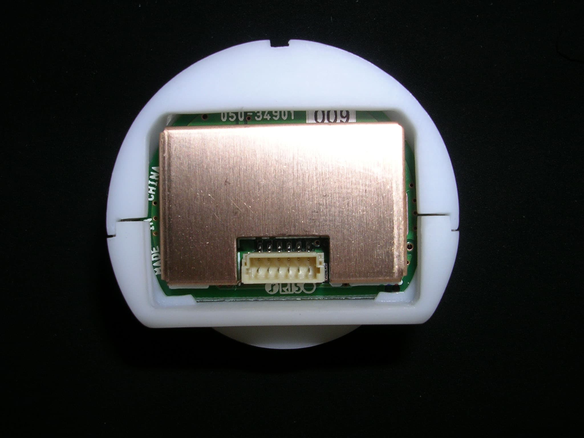
FCC ID: RPARFM3L00 FCC ID: RPARFM3L00 FCC ID: RPARFM3L00 FCC ID: RPARFM3L00 FCC ID: RPARFM3L00 FCC ID: RPARFM3L00 FCC ID: RPARFM3L00 FCC ID: RPARFM3L00 RF-MODULE Antenna (O-Shape) Antenna (D-Shape)
Operational Description
FCC ID: RPARFM3L00 Operational Description The duplicator scans the original by the scanner and processes the image in the CTL-PCB. The master making unit then receives the processed image and perforates the image on to the master. The master is then loaded on to the drum unit and the ink inside the drum unit is transferred on to a paper via perforated holes on the master. The RF Board (No. 1 on the Block Diagram) is supplied by 5Vdc from the Power Supply (2) of the duplicator, and under the control of the CTL-PCB (3) built in the duplicator. (Electrically, the 5Vdc is directly from the duplicator’s Power Supply, although it is through the CTL-PCB physically.) Connected on the RF Board are two Antennas: one in an “O” shape (4) and for communication with the RF-TAG pasted on the master roll (5); the other in a “D” shape (6) and for communication with the RF-TAG pasted on the ink bottle (7). As soon as the duplicator is turned on, information of the master and the ink stored in the RF-TAGs is read by the RF Board, through the Antennas, and sent to the CTL-PCB, where it is used to adjust the duplicator (to the most suitable condition). Every time the duplicator starts master-making, information of the master (stored in the RF-TAG on the master roll) is updated by the RF Board (through the O-shape Antenna). When the duplicator prints, information of the ink is regularly updated in a similar way. The RF-TAG has no internal power supply. The RF-TAG can only transmit data, while receiving electromagnetic field from the RF-MODULE. Therefore, the RF-TAG is passive and can not transmit data by itself.
Test Report
This laboratory is accredited by American Association For Laboratory Accreditation. The tests reported herein have been performed Certificate No. 952.01/952.02/952.03 in accordance with its terms of accreditation. Test Report No. Issue Date EUT Information : FCC CFR 47 Part 15, Subpart C with exception of 15.31(e) and 15.225(c) requirements Trade Name Category: Duplicator with RFID System Model Name: RZ390UI Serial Number: 81340003 Japan EMC Laboratory Limited TEST REPORT : RISO Applied Standard : R141475 : January 9, 2004 JAPAN EMC LABORATORY LTD Issue date : Japan EMC Laboratory LimitedReport No.:Page 2 of 78 Contents Text Page Contents ----------------------------------------------------------------------- 2 Scope ------------------------------------------------------------------------- - 3 Certification ----------------------------------------------------------------- - 4 Brief Information ------------------------------------------------------------ 6 Test Procedure --------------------------------------------------------------- 8 Radiated Emission Measurement --------------------------- - 8 Conducted Emission Measurement ------------------------- 9 Configuration of the EUT -------------------------------------------------- 10 Condition of the EUT ------------------------------------------------------- 12 List of test equipment used for the test ---------------------------------- - 13 Test results ------------------------------------------------------------------ - 14 Radiated disturbance ----------------------------------------- - 14 Conducted disturbance --------------------------------------- - 56 Photograph of the EUT ----------------------------------------------------- 76 January 9, 2004 R141475 Issue date : Japan EMC Laboratory LimitedReport No.: R141475Page 3 of 78 Scope January 9, 2004 This document is a report of the radiated emission and conducted power line tests performed for the Duplicator Model Name: RZ390UI with RFID system. Issue date : Japan EMC Laboratory LimitedReport No.: R141475Page 5 of 78 Table 1 Result 15.27Pass 47CFR Part #Comments 15.15(b)Pass The product contains no user accessible controls that increase transmission power above allowable levels. 2.92515.19Pass The label is shown in the label exhibit. (The label exhibit is not part of this test report) 15.21Pass Information to the user is shown in the instruction manual exhibit. (The instruction manual exhibit is not part of this test report) No special accessories are required for compliance. 15.31(e) 15.225( c ) Test not performed The frequency tolerance of the carrier signal with 0.01% of the operating frequency was not confirmed. The input power should be varied from its nominal value(120V) to 102V and 138V. The respective radiated power measurement was not performed. 15.203Pass The device utilizes a unique antenna connector, antenna is located inside of the equipment under test and not accessible by the end user. 15.205 15.209 Pass The fundamental is not in a Rrestricted band and the spurious emissions in the Restricted bands comply with the general emission limits of 15.209. 15.204Pass Refer to antenna description(s). Only the build in antennas are to be used with the equipment under test. January 9, 2004 15.225(a)Pass The field strength of emissions within the band of 13.553- 13.567MHz is less than 15,848μV/m at 30m. 15.207Pass Conducted EMI data on AC side of the power supply is provided in this report. Issue date : Japan EMC Laboratory LimitedReport No.: R141475Page 6 of 78 Brief Information 1.Test summary Test was done for compliance with Frequency range to be scanned : Open site: 1300B3 A sample calculation : COR. F(correction factor)= Antenna factor+Cable loss- Amp.gain - Distance correction Emission Level= meter readin g + COR.F Shielded enclosure : 6.3 meter by 5.4 meter and 2.5 meter high in size for AC powerline conducted measurement. Detector Function and Selection of Bandwidth : Measured by the CISPR quasi-peak function Bandwidth is 10kHz in the frequency 0.15MHz to 30MHz and 120kHz in the frequency 30MHz to 1,000MHz and 1MHz in the fre quency above 1GHz. File Refer NO. : 31040/SIT Site location : 2971 Nakabyo, Abiko-City 270-1121, Japan January 9, 2004 FCC Rules & Regulations Part 15C(47CFR 15C) updates as of Dec.8, 2003. ANSI. C. 63.4: 2001, EIA/TIA 603, MP- 5 Radiated : 30-1000MHz. 1GHz-2GHz. Conducted:0.15-30MHz. Filed with FCC Authorization and Evaluation division 7435 Oakland Mills Rd Columbia, MD 21046, U.S.A. on Feb.4, 2002. AVAILABLE FOR ANSI C63. 4-2001. Issue date : Japan EMC Laboratory LimitedReport No.: R141475Page 7 of 78 2. Product description 3. Test configurations 4. Operation 5. Comment of the Measurement By the method of MP-5, preliminary consideration are carried out for all available mode and cable layouts for each frequency. Measurement was made maximum configuration for each frequency. The test results were found to be below the limits of FCC part 15 subpart C digital devices. The minimum margins to the limits are 4.0 dBuV/m at 38.41MHz at radiated emission measurement in the I/F parallel print mode and 2.4 dBuV at 1.07 MHz at conducted power line measurement in the stand-by mode. Radiated emission level above 1754MHz of this equipment under test was far below from FCC limits. The test regarding as 15.31(e) and 15.225(c) was not performed. See page5 for the detail. January 9, 2004 The Equipment under the test is a digital duplicator which is able to make a print by scanning an original or sending image data from PC directly and via network. The printing sizes are up to A3 (US Ledger size) and the printing speeds are variable 60 rpm to 130 rpm. Scan is performed at a resolution D600 dpi and the highest clock frequency used in the EUT is 133MHz, which means that the measurement range for the EUT is up to 2000 MHz according to Section 15.33, FCC part 15 . The electrical rating of the EUT is 120 volt AC which frequency range is 50/60 Hz and 2.5 ampere. 3.0 meter non-shi…
Text truncated - open the document above for the full version.
Test Report
JAPAN QUALITY ASSURANCE ORGANIZATION 21-25, KINUTA 1-CHOME, SETAGAYA-KU, TOKYO 157-8573 JAPAN PHONE (03) 3416-0111, TELEX 242-2531 JQA J FAX (03) 3416-9691 JQA APPLICATION NO.: 400-30742 Issue Date : January 7, 2004 Page 1 of 24 EMI TEST REPORT JQA APPLICATION NO. : 400-30742 Model No. : RZ390UI Type of Equipment : Duplicator with RFID System Regulations Applied : CFR 47 FCC Rules and Regulations Part 15.225(e) FCC ID : RPARFM3L00 Applicant : Riso Kagaku Corporation Address : 127-7 Taninosawa, Fukuda, Ami-machi, Inashiki-gun, Ibaraki-ken 300-1156, Japan Manufacturer : Riso Kagaku Corporation Address : 127-7 Taninosawa, Fukuda, Ami-machi, Inashiki-gun, Ibaraki-ken 300-1156, Japan Received date of EUT : January 6, 2004 Final Judgment : Passed Test results in this report are obtained in use of equipment that is traceable to National Institute of Advanced Industrial Science and Technology (AIST) of Japan and Communication Research Laboratory (CRL) of Japan. The test results only respond to the tested sample. This report should not be reproduced except in full, without the written approval of JQA EMC Engineering Dept. Testing Div. C O P Y JQA Application No. :400-30742 FCC ID :RPARFM3L00 Model No. :RZ390UI Issue Date :January 7, 2004 Standard :CFR 47 FCC Rules Part 15 Page 2 of 24 JAPAN QUALITY ASSURANCE ORGANIZATION TABLE OF CONTENTS Page 1 Documentation 1.1 Test Regulation 3 1.2 General Information 3 1.3 Test Condition 4 – 8 1.4 EUT Modifications / Deviation from Standard 9 1.5 Test results 10 1.6 Summary 11 1.7 Test Configuration / Operation of EUT 12 1.8 EUT Arrangement(Drawing) 13 1.9 Preliminary Test and Test-setup (Drawings) 14 – 19 2 Test Data 2.1 AC Power Line Conducted Emission N/T 2.2 Radiated Emission (Electric Field) N/T 2.3 Frequency Stability 20 2.4 Occupied Bandwidth N/T 2.5 AC Power Line Conducted Emission for Receiver N/A 2.6 Radiated Emission (Electric Field) for Receiver N/A 3 Appendix Test instruments List 21 – 24 C O P Y JQA Application No. :400-30742 FCC ID :RPARFM3L00 Model No. :RZ390UI Issue Date :January 7, 2004 Standard :CFR 47 FCC Rules Part 15 Page 3 of 24 JAPAN QUALITY ASSURANCE ORGANIZATION 1 DOCUMENTATION 1.1 TEST REGULATION At the request of the applicant, FCC Rules and Regulations Part 15 Subpart C section 225(e) was applied. Test procedure : AC power line conducted emission, radiated emission, frequency stability and occupied bandwidth tests were performed according to the procedures in ANSI C63.4-2001. 1.2 GENERAL INFORMATION 1.2.1 Test facility : 1) Test Facility located at EMC Engineering Dept. Testing Div. : - No.2 and 3 Anechoic Chambers( 3 meters Site ). - Shielded Enclosure. Expiration date of FCC test facility filing : May 27, 2005 2) EMC Engineering Dept. Testing Div. is recognized under the National Voluntary Laboratory accreditation Program for satisfactory compliance established in title 15, Part 285 Code of Federal Regulations. NVLAP Lab Code : 200189-0 (Effective through : June 30, 2004) 1.2.2 Description of the Equipment Under Test (EUT) : 1) Type of Equipment : Duplicator with RFID System 2) Product Type : Production Prototype 3) Category : Low Power Communication Device Transmitter 4) EUT Authorization : Certification 5) FCC ID : RPARFM3L00 6) Trade Name : RISO 7) Model No. : RZ390UI 8) Operating Frequency Range : 13.56MHz 9) Highest Frequency Used in the EUT : 13.56MHz 10) Serial No. : 81340003 11) Date of Manufacture : - 12) Power Rating : AC120V, 60Hz 13) EUT Grounding : Grounded at the plug end of the power line cord. 1.2.3 Definitions for symbols used in this test report : x - indicates that the listed condition, standard or equipment is applicable for this report. - indicates that the listed condition, standard or equipment is not applicable for this report. C O P Y JQA Application No. :400-30742 FCC ID :RPARFM3L00 Model No. :RZ390UI Issue Date :January 7, 2004 Standard :CFR 47 FCC Rules Part 15 Page 4 of 24 JAPAN QUALITY ASSURANCE ORGANIZATION 1.3 TEST CONDITION 1.3.1 The measurement of the AC Power Line Conducted Emission - was performed in the following test site. x - was not applicable. Test location : Safety & EMC Center EMC Engineering Dept. Testing Div. 21-25, Kinuta 1-chome, Setagaya-ku, Tokyo 157-8573, Japan - Shielded Enclosure - Anechoic Chamber No. 2 (portable Type) Used test instruments : Type Number of test instruments (Refer to Appendix) Test Receiver N/A Spectrum Analyzer N/A Cable N/A AMN(for EUT) N/A AMN(for Peripheral) N/A Termination N/A C O P Y JQA Application No. :400-30742 FCC ID :RPARFM3L00 Model No. :RZ390UI Issue Date :January 7, 2004 Standard :CFR 47 FCC Rules Part 15 Page 5 of 24 JAPAN QUALITY ASSURANCE ORGANIZATION 1.3.2 The measurement of the Radiated Emission(9 kHz – 30 MHz) - was performed in the following test site. x - was not applicable. Test location : Safety & EMC Center EMC Engineering Dept. Testing Div. 21-25, Kinuta 1-chome, Setagaya-ku, Tokyo 157-8573, Japan - Anechoic Chamber No. 2 (3 meters) - Anechoic Chamber No. 3 (3 meters) Validation of Site Attenuation : 1) Last Confirmed Date : N/A 2) Interval : N/A Used test instruments : Type Number of test instruments (Refer to Appendix) Test Receiver N/A Antenna N/A Cable N/A C O P Y JQA Application No. :400-30742 FCC ID :RPARFM3L00 Model No. :RZ390UI Issue Date :January 7, 2004 Standard :CFR 47 FCC Rules Part 15 Page 6 of 24 JAPAN QUALITY ASSURANCE ORGANIZATION 1.3.3 The measurement of the Radiated Emission(30 MHz – 1000 MHz) - was performed in the following test site. x - was not applicable. Test location : Safety & EMC Center EMC Engineering Dept. Testing Div. 21-25, Kinuta 1-chome, Setagaya-ku, Tokyo 157-8573, Japan - Anechoic Chamber No. 2 (3 meters) - Anechoic Chamber No. 3 (3 meters) Validation of Site Attenuation : 1) Last Confirmed Date :March, 2003 2) Interval :1 year Used test instruments : Type Number of test instruments (Refer to Appendix) Test Receiver N/A Antenna N/A Cable N/A RF Amplifier N/A C O P Y JQA Application No. :400-30742 FCC…
Text truncated - open the document above for the full version.
Test Report
JAPAN QUALITY ASSURANCE ORGANIZATION 21-25, KINUTA 1-CHOME, SETAGAYA-KU, TOKYO 157-8573 JAPAN PHONE (03) 3416-0111, TELEX 242-2531 JQA J FAX (03) 3416-9691 JQA APPLICATION NO.: 441-30938 Issue Date :January 14, 2004 Page 1 of 12 EMI TEST REPORT JQA APPLICATION NO. : 441-30938 Model No. : RZ390UI Type of Equipment : Duplicator with RFID System Regulations Applied : CFR 47 FCC Rules and Regulations Part 15 FCC ID : RPARFM3L00 Applicant : RISO KAGAKU CORPORATION Address : 127-7, Taninosawa, Fukuda, Ami-machi, Inashiki-gun Ibaraki-ken 300-1156, Japan Manufacture : RISO KAGAKU CORPORATION Address : 127-7, Taninosawa, Fukuda, Ami-machi, Inashiki-gun Ibaraki-ken 300-1156, Japan Received date of EUT : January 14, 2000 Final Judgment : Passed TEST RESULTS IN THIS REPORT are obtained in use of equipment that is traceable to National Institute of Advanced Industrial Science and Technology (AIST) of Japan and Communication Research Laboratory (CRL) of Japan. The test results only responds to the tested sample. THIS REPORT should not be reproduced, except in full, without the approval of the JQA Safety & EMC Center EMC Engineering Department TSURU EMC Branch This report must not used by the client to claim product endorsement by NVLAP or any agency of the U.S. Government. NVLAP LAB CODE : 200192-0 JQA Application No. :441-30938 FCC ID :RPARFM3L00 Model No. :RZ390UI Issue Date :January 14, 2004 Standard :CFR 47 FCC Rules Part 15 Page 2 of 12 JAPAN QUALITY ASSURANCE ORGANIZATION TABLE OF CONTENTS Page 1 Documentation 1.1 Test Regulation 3 1.2 General Information 3 1.3 Test Condition 4 1.4 EUT Modifications / Deviation from Standard 5 1.5 Test results 6 1.6 Summary 7 1.7 Test Configuration / Operation of EUT 8 1.8 EUT Arrangement(Drawing) 9 1.9 Preliminary Test and Test-setup (Drawings) 10 1.10 EUT Arrangement (Photographs) 11 2 Test Data 2.1 Radiated Emission (Electric Field)9 kHz – 30 MHz 12 JQA Application No. :441-30938 FCC ID :RPARFM3L00 Model No. :RZ390UI Issue Date :January 14, 2004 Standard :CFR 47 FCC Rules Part 15 Page 3 of 12 JAPAN QUALITY ASSURANCE ORGANIZATION 1. DOCUMENTATION 1.1 TEST REGULATION FCC Rules and Regulations Part 15 Subpart A and C Intentional Radiator. Test procedure : AC powerline conducted emissions and radiated emissions tests were performed according to the procedures in ANSI C63.4-2001. 1.2 GENERAL INFORMATION 1.2.1 Test facility : 1) Test Facility located at JQA Safety & EMC Center EMC Engineering Department TSURU EMC Branch: Open Site No.1, No.2, An Anechoic Chamber (3 m and 10 m, on common plane)and a Shielded Room FCC Registration Number: 90728 (Date of Listing : April 2, 2002) 2) JQA Safety & EMC Center EMC Engineering Department TSURU EMC Branch is recognized under the National Voluntary Laboratory Accreditation Program for satisfactory compliance established in title 15, Part 285 Code of Federal Regulations. NVLAP Lab Code : 200192-0 (Effective through : June 30, 2004) 1.2.2 Description of the Equipment Under Test (EUT) : 1) Type of Equipment : Duplicator with RFID System 2) Product Type : Pre-Production 3) Category : Low Power Communication Device 4) EUT Authorization : Certification 5) FCC ID : RPARFM3L00 6) Trade Name : RISO 7) Model No. : RZ390UI 8) Operating Frequency Range : 13.56 MHz 9) Serial No. : 81340003 10) Date of Manufacture : - 11) Power Rating : 120VAC, 60Hz 13) EUT Grounding : Grounded at the plug end of the powerline cord None 1.2.3 Definitions for symbols used in this test report : x - indicates that the listed condition, standard or equipment is applicable for this report. - indicates that the listed condition, standard or equipment is not applicable for this report. JQA Application No. :441-30938 FCC ID :RPARFM3L00 Model No. :RZ390UI Issue Date :January 14, 2004 Standard :CFR 47 FCC Rules Part 15 Page 4 of 12 JAPAN QUALITY ASSURANCE ORGANIZATION 1.3 TEST CONDITION 1.3.1 The measurement of the Radiated Emission(9 kHz – 30 MHz) x - was performed in the following test site. - was not applicable. Test location : JQA Safety & EMC Center EMC Engineering Department TSURU EMC Branch 2096 Ohata, Tsuru-shi Yamanashi-ken 402-0045, JAPAN X - Anechoic Chamber - Open Site No.1 - Open Site No.2 Used test instruments : Type Model No. Manufacturer Serial No. Last Cal. Interval X - Test Receiver(R-7) ESI7 Rohde & Schwarz 100059 2003/10 1 Year - Test Receiver(R-8) ESCS30 Rohde & Schwarz 100203 2003/2 1 Year - Test Receiver(R-1) ESHS30 Rohde & Schwarz 842053/001 2003/11 1 Year X - Loop Antenna(A-17) HFH2-Z2 Rohde & Schwarz 879284/14 2003/5 1 Year JQA Application No. :441-30938 FCC ID :RPARFM3L00 Model No. :RZ390UI Issue Date :January 14, 2004 Standard :CFR 47 FCC Rules Part 15 Page 5 of 12 JAPAN QUALITY ASSURANCE ORGANIZATION 1.4 EUT MODIFICATION / Deviation from Standard 1.4.1 EUT MODIFICATION x - No modifications were conducted by JQA to achieve compliance to applicable limits. - To achieve compliance to applicable limits, the following changes were made by JQA during the compliance test. 1.4.2 Deviation from Standard: x - No deviations from the standard described in clause 1.1. - The following deviations were employed from the standard described in clause 1.1: Applicant : Date : Typed Name : Position : The modifications will be implemented in all production models of this equipment. JQA Application No. :441-30938 FCC ID :RPARFM3L00 Model No. :RZ390UI Issue Date :January 14, 2004 Standard :CFR 47 FCC Rules Part 15 Page 6 of 12 JAPAN QUALITY ASSURANCE ORGANIZATION 1.5 TEST RESULTS Radiated Emission [§15.225(a)(b)(c)(d)] x - Applicable - NOT Applicable The requirements are x - PASSED - NOT PASSED Remarks: JQA Application No. :441-30938 FCC ID :RPARFM3L00 Model No. :RZ390UI Issue Date :January 14, 2004 Standard :CFR 47 FCC Rules Part 15 Page 7 of 12 JAPAN QUALITY ASSURANCE ORGANIZATION 1.6 SUMMARY General Remarks : The EUT was tested according to the requirements of FCC Rules and Regulations Part 15 Subpart A and C under the test configuration, as shown in clause …
Text truncated - open the document above for the full version.
Contact Information
Applicant
Tomokazu Sugiyama(Regulation Manager)
Technical Contact
RISO KAGAKU CORPORATIONToru Matsushita
[email protected]+81-029-840-3159
127-7,Taninosawa,Fukuda · Inashiki-gun, Ibaraki · Japan
Non-Technical Contact
RISO KAGAKU CORPORATIONToru Matsushita
[email protected]+81-029-840-3159
Test Firm
Japan EMC Laboratory, Ltd.Takayuki Okawara
Technical Specifications
| # | Rule Parts | Frequency Range | Power Output |
|---|---|---|---|
| 1 | 15C | 13.56 MHz - 13.56 MHz | - |
Other Applications from Riso Kagaku Corporation
RPARFR6
Sep 09, 2008RFID Tag Reader/Writer
Equipment Class
DXX - Part 15 Low Power Communication Device Transmitter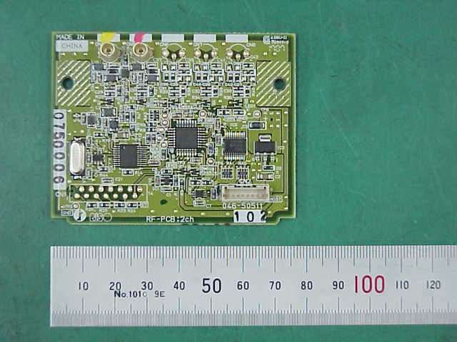
RPARFA3B
Feb 03, 2008RF Module(RFID Tag Reader/Writer)
Equipment Class
DXT - Part 15 Low Power Transceiver, Rx Verified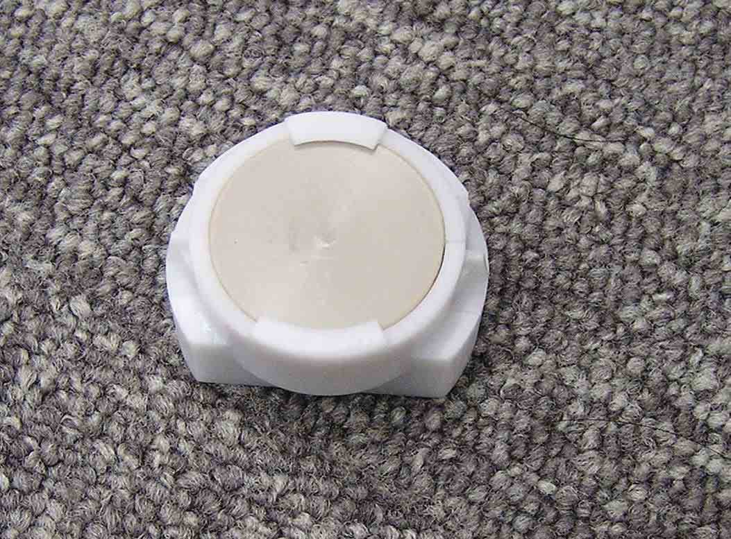
RPARFOM5
Sep 05, 2007RF Module(RFID Tag Reader/Writer)
Equipment Class
DXX - Part 15 Low Power Communication Device Transmitter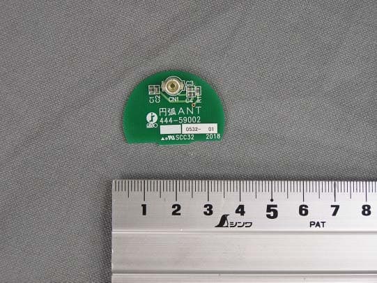
RPARFA3A
Sep 08, 2005RF-Module (RFID Tag Reader/Writer)
Equipment Class
DXT - Part 15 Low Power Transceiver, Rx Verified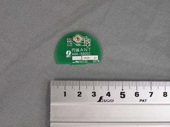
RPARFA3
Sep 05, 2005RF-Module (RFID TAG Reader/Writer)
Equipment Class
DXT - Part 15 Low Power Transceiver, Rx Verified