RPW-CM210Instant Color Picking
BCM Communication Co., Ltd.
Click to zoom
Application Details
- Equipment Class
- DTS - Digital Transmission System
- Date of Grant
- Jun 01, 2026
- Application Purpose
- Original Equipment
- Equipment Note
- Instant Color Picking
- Frequency Range
- 2402.00000000 - 2480.00000000
- Company
- BCM Communication Co., Ltd.
- Country
- Taiwan
Documents & Files
Document Text
Text extracted from the exhibit documents filed with the FCC. Open a document above to read the original.
Users Manual
Instant Color Picking 2 InstaPick 2 × 1 Calibration Cap (Ref. White) ×1 USB Type-C charging cable × 1 User manual × 1 Overview Sensor Calibration cap Charging Method Connect the Type-C cable to the charging port on the side of the device. Fully charge the device before first use. Recharge the device when battery level is below 20%. Indicator Light Charging:LED blinking Fully charged:LED solid App Prompts Bottom-left capsule shows battery %. Red icon indicates low battery. Charging Port Charging Instructions Color Judge 2 Color Judge 2Color Judge 2 System support Color Judge 2 Supported OS Android 10.0 or later iOS 13.0 or later Windows 10 or later macOS 11.0 or later No Pairing Required Direct in-app connection via BLE. No system Bluetooth pairing needed. Color Judge 2 Color Judge 2Color Judge 2 Color Judge 2 Color Judge 2Color Judge 2 Long press Press First Time Usage Download & Install App Scan the QR code to download the app (Color Judge 2). For more information: https://campsite.bio/ufroinstapick 1 2 ( No system settings pairing required ) Enable Bluetooth Ensure Bluetooth is enabled on your device. 3 Initial Pairing Open the app. Place the color picker near your device press the button once. ( Enable Bluetooth and permissions ) Connected Put on the calibration cap → Press once → Wait for calibration When the app requests white calibration Align the sensor aperture with the target color. Start Using 1 2 Press the device. Color appears in the app. Press Thank you for your interest in the InstaPick2 The information contained in this manual is necessary when using the InstaPick2. Please read through the document before using the InstaPick2. Operating environment Device with Bluetooth® BLE Windows 10 or later versions MacOS 11.0 or later versions Please refer to our website for information on compatible APPs FCC warning Changes or modifications not expressly approved by the party responsible for compliance could void the user’s authority to operate the equipment. The environment and equipment described below is required to use this product. Notice This equipment has been tested and found to comply with the limits for a class B digital device, pursuant to part 15 of the FCC Rules. These limits are designed to provide reasonable protection against harmful interference in a residential installation. This equipment generates, uses and can radiate radio frequency energy and, if not installed and used in accordance with the instructions, may cause harmful interference to radio communications. However, there is no guarantee that interference will not occur in a particular installation. If this equipment does cause harmful interference to radio or television reception, which can be determined by turning the equipment off and on, the user is encouraged to try to correct the interference by one or more of the following measures: About the RF Exposure CE Reorient or relocate the receiving antenna. Increase the separation between the equipment and receiver. Connect the equipment into an outlet on a circuit different from that to which the receiver is connected. Consult the dealer or an experienced radio / TV technician for help. This device complies with Part 15 of the FCC Rules. Operation is subject to the following two conditions: (1) This device may not cause harmful interference, and (2) this device must accept any interference received, including interference that may cause undesired operation. This class B digital apparatus complies with Canadian ICES-003. Cet appareil numérique de la classe B est conforme à la norme NMB-003 du Canada. This transmitter must not be co-located or operated in conjunction with any other antenna or transmitter. This equipment complies with FCC / IC radiation exposure limits set forth for uncontrolled equipment and meets the FCC radio frequency (RF) Exposure Guidelines in Supplement C to OET65 and RSS-102 of the IC radio frequency (RF) Exposure rules. This transmitter must not be co-located or operated in conjunction with any other antenna or transmitter. This product is in conformity with the relevant Union harmonization legislation: Radio Equipment Directive: 2014/53/EU With reference to the following standards applied: EN 300 328 V2.2.2 (2019-07) EN 62311:2008 EN 301 489-1 V2.2.3 (2019-11) EN 301 489-17 V3.1.1 (2017-02) The frequency and maximum transmitted power in EU are listed as below 2412-2472 MHz 4.21 dBM Model Name: InstaPick 2 (CM210) Size: 31.5x31.5x40mm Material: PC+ABS Net Weight: 27g Make in Taiwan Ufro Inc. 10F, No. 102, Sec. 1, Yanping N. Rd., Datong Dist., Taipei City 103012, Taiwan (R.O.C.) https://tw.instapick.ufro.com/
External Photos
International Standards Laboratory Corp. Report Number: ISL-26LR0062P Appendix Photographs of EUT of Product Name Instant Color Picking Main Model InstaPick 2 Series Model 無 Brand InstaPick International Standards Laboratory Corp. Report Number: ISL-26LR0062P -1- EUT-1. EUT-2. International Standards Laboratory Corp. Report Number: ISL-26LR0062P -2- EUT-3. EUT-4. International Standards Laboratory Corp. Report Number: ISL-26LR0062P -3- EUT-5. EUT-6. International Standards Laboratory Corp. Report Number: ISL-26LR0062P -4- EUT-7. EUT-8.
ID Label/Location Info
FCC ID LABEL FORMAT AND LOCATION Applicant: BCM Communication Co., Ltd. FCC ID: RPW-CM210
Internal Photos
International Standards Laboratory Corp. Report Number: ISL-26LR0062P Appendix Photographs of EUT of Product Name Instant Color Picking Main Model InstaPick 2 Series Model 無 Brand InstaPick International Standards Laboratory Corp. Report Number: ISL-26LR0062P -1- EUT-1. EUT-2. International Standards Laboratory Corp. Report Number: ISL-26LR0062P -2- EUT-3. EUT-4. A8107M0 International Standards Laboratory Corp. Report Number: ISL-26LR0062P -3- EUT-5. antenna EUT-6. battery
RF Exposure Info
FCC: RPW-CM210 International Standards Laboratory Report Number: ISL-26LR0062FMPE RF Exposure Report Standard Applicable For The radiation source included into the device the output power is taken from a corresponding RF test report. If needed the output power is converted to source based, time – average out power. Finally the output power is compared to FCC and IC low power SAR evaluation exemption level. According to §2.1093 this is a Portable device. FCC SAR test exclusion: According to KDB 447498 D01 General RF Exposure Guidance v06, Appendix A requirement, “The equation and threshold in section 4.3.1 must be applied to determine SAR test exclusion.” 4.3.1. Standalone SAR test exclusion considerations Unless specifically required by the published RF exposure KDB procedures, standalone 1-g head or body and 10-g extremity SAR evaluation for general population exposure conditions, by measurement or numerical simulation, is not required when the corresponding SAR Test Exclusion Threshold condition, listed below, is satisfied. These test exclusion conditions are based on source-based time-averaged maximum conducted output power of the RF channel requiring evaluation, adjusted for tune-up tolerance, and the minimum test separation distance required for the exposure conditions.23 The minimum test separation distance is determined by the smallest distance from the antenna and radiating structures or outer surface of the device, according to the host form factor, exposure conditions and platform requirements, to any part of the body or extremity of a user or bystander (see 5) of section 4.1). To qualify for SAR test exclusion, the test separation distances applied must be fully explained and justified by the operating configurations and exposure conditions of the transmitter and applicable host platform requirements, typically in the SAR measurement or SAR analysis report, according to the required published RF exposure KDB procedures. When no other RF exposure testing or reporting is required, a statement of justification and compliance must be included in the equipment approval, in lieu of the SAR report, to qualify for the SAR test exclusion. When required, the device specific conditions described in the other published RF exposure KDB procedures must be satisfied before applying these SAR test exclusion provisions; for example, handheld PTT two-way radios, handsets, laptops & tablets etc.24 FCC: RPW-CM210 International Standards Laboratory Report Number: ISL-26LR0062FMPE 1) The 1-g and 10-g SAR test exclusion thresholds for 100 MHz to 6 GHz at test separation distances ≤ 50 mm are determined by: [(max. power of channel, including tune-up tolerance, mW)/(min. test separation distance, mm)] · [√f(GHz)] ≤ 3.0 for 1-g SAR and ≤ 7.5 for 10-g extremity SAR,25 where • f(GHz) is the RF channel transmit frequency in GHz • Power and distance are rounded to the nearest mW and mm before calculation26 • The result is rounded to one decimal place for comparison • 3.0 and 7.5 are referred to as the numeric thresholds in the step 2 below The test exclusions are applicable only when the minimum test separation distance is ≤ 50 mm and for transmission frequencies between 100 MHz and 6 GHz. When the minimum test separation distance is < 5 mm, a distance of 5 mm according to 5) in section 4.1 is applied to determine SAR test exclusion. Evaluation Result: FCC: Frequency (MHz) Output Power (dBm) Antenna Gain (dBi) EIRP (dBm) Tune-up Tolerance (dB) Max Power (mW) Min Distance (mm) Result Limit (3.0 @ 1g SAR) 2402 -1.41 -0.30 -1.71 1 0.85 5.00 0.27 3.0 Max Power(mW) =10^((Max Power(dBm) Antenna Gain+ Tune-up tolerance(dB) )/10) Result = Max Power (mW) / min. distance(mm) * √f(GHz) ~ end ~
Test Report
TEST REPORT of FCC CFR Title 47 Part 15 Subpart C Product: Instant Color Picking Brand: InstaPick Main Model: InstaPick 2 Series Model: NA FCC ID: RPW-CM210 Standard: §15.247, Cat: DTS Reference: ANSI C63.10: 2020 KDB 558074 D01 v05r02 Applicant: BCM Communication Co., Ltd. Address 8Fl, No. 3, WoLung St., Taipei, Taiwan R.O.C. Test Performed by: International Standards Laboratory Corp. LT Lab. TEL: +886-3-263-8888 FAX: +886-3-263-8899 No. 120, Lane 180, Hsin Ho Rd., Lung-Tan Dist., Tao Yuan City 325, Taiwan Report No.: ISL-26LR0062FCBLE Issue Date : April 28, 2026 FCC Registration Number: 487532 Test results given in this report apply only to the specific sample(s) tested and are traceable to national or international standard through calibration of the equipment and evaluating measurement uncertainty herein. According to customer agreement, the laboratory issues test reports based on the regulations or standards specifications, the measurement uncertainty is not considered in conformity decision rules. This test report shall not be reproduced except in full, without the written approval of International Standards Laboratory Corp. -2 of 54- International Standards Laboratory Corp. Report Number: ISL-26LR0062FCBLE VERIFICATION OF COMPLIANCE Applicant: BCM Communication Co., Ltd. Equipment Under Test: Instant Color Picking Brand: InstaPick Main Model: InstaPick 2 Series Model: NA Model Difference: NA FCC ID: RPW-CM210 Date of Test: April 9, 2026 ~ April 28, 2026 Date of EUT Received: April 9, 2026 APPLICABLE STANDARDS STANDARD TEST RESULT FCC Part 15.247 Complied We hereby certify that: All the tests in this report have been performed and recorded in accordance with the standards described above and performed by an independent electromagnetic compatibility consultant, International Standards Laboratory Corp. The test results contained in this report accurately represent the measurements of the characteristics and the energy generated by sample equipment under test at the time of the test. The sample equipment tested as described in this report is in compliance with the limits of above standards. Prepared By: Gigi Yeh Test By: Approved By: Barry Lee Jerry Liu / Manager -3 of 54- International Standards Laboratory Corp. Report Number: ISL-26LR0062FCBLE Version Version No. Date Description 00 April 28, 2026 Initial creation of document -4 of 54- International Standards Laboratory Corp. Report Number: ISL-26LR0062FCBLE TABLE OF CONTENTS 1. Description of Equipment under Test (EUT) .......................................................................... 5 2. Description of Test Modes ......................................................................................................... 6 2.1 CONFIGURATION OF TESTED SYSTEM .............................................................................................. 6 2.2 DUTY FACTOR .................................................................................................................................. 7 3. Standards, reference documents and applicable test methods .............................................. 8 4. Summary of Test Results ........................................................................................................... 8 5. AC Line Conduced Emission Test ............................................................................................ 9 5.1 STANDARD APPLICABLE .................................................................................................................. 9 5.2 MEASUREMENT PROCEDURE............................................................................................................ 9 5.3 MEASUREMENT RESULT..................................................................................................................10 6. Peak Output Power Measurement ......................................................................................... 12 6.1 STANDARD APPLICABLE .................................................................................................................12 6.2 MEASUREMENT PROCEDURE...........................................................................................................12 6.3 MEASUREMENT RESULT..................................................................................................................13 7. Radiated Spurious Emission Test ........................................................................................... 14 7.1 STANDARD APPLICABLE .................................................................................................................14 7.2 MEASUREMENT PROCEDURE...........................................................................................................14 7.3 FIELD STRENGTH CALCULATION ....................................................................................................15 7.4 MEASUREMENT RESULT..................................................................................................................16 8. 100kHz Bandwidth of Band Edges Measurement ................................................................ 29 8.1 STANDARD APPLICABLE .................................................................................................................29 8.2 MEASUREMENT PROCEDURE...........................................................................................................29 8.3 FIELD STRENGTH CALCULATION ....................................................................................................29 8.4 MEASUREMENT RESULT..................................................................................................................30 9. 6dB Bandwidth ......................................................................................................................... 35 9.1 STANDARD APPLICABLE .................................................................................................................35 9.2 MEASUREMENT PROCEDURE.....…
Text truncated - open the document above for the full version.
Test Report
BCM Computers Co., Ltd. 8Fl,No.3,WoLung St.,Taipei,Taiwan R.O.C. TEL: +886(3)250-4731 FAX: +886(3)3226427 Antenna specification Model name: NA Antenna type: PCB antenna Connector type: IPEX Antenna manufacturer: BCM Antenna maximum gain: -0.3dBi Center Frequency 2402 MHz -3.61dBi 2440 MHz -0.48dBi 2480 MHz -0.3dBi Antenna pattern: 2402 BCM Computers Co., Ltd. 8Fl,No.3,WoLung St.,Taipei,Taiwan R.O.C. TEL: +886(3)250-4731 FAX: +886(3)3226427 2440 BCM Computers Co., Ltd. 8Fl,No.3,WoLung St.,Taipei,Taiwan R.O.C. TEL: +886(3)250-4731 FAX: +886(3)3226427 2480
Test Setup Photos
-48 of 54- International Standards Laboratory Corp. Report Number: ISL-26LR0062FCBLE 11.4 Appendix D: Photographs of Setup Conducted Emission Set up Photo -49 of 54- International Standards Laboratory Corp. Report Number: ISL-26LR0062FCBLE -50 of 54- International Standards Laboratory Corp. Report Number: ISL-26LR0062FCBLE Radiated Emission Set up Photos -51 of 54- International Standards Laboratory Corp. Report Number: ISL-26LR0062FCBLE -52 of 54- International Standards Laboratory Corp. Report Number: ISL-26LR0062FCBLE -53 of 54- International Standards Laboratory Corp. Report Number: ISL-26LR0062FCBLE -54 of 54- International Standards Laboratory Corp. Report Number: ISL-26LR0062FCBLE 11.5 Appendix E: Photographs of EUT Please refer to the File of ISL-26LR0062P --- END ---
Contact Information
Applicant
Frank Chou(Senior Product Manag)
[email protected]Fax: 886-3-322-9584
Technical Contact
Americas Compliance consulting, LLC dba iCertifiPaul Preston
2445 NE Division Street, Suite 202 Bend, · OR 97703 · United States
Test Firm
International Standards Laboratory Corp.Benson Chen
[email protected]Fax: 886-3-263-8899
Technical Specifications
| # | Rule Parts | Frequency Range | Power Output |
|---|---|---|---|
| 1 | 15C | 2.40 GHz - 2.48 GHz | 650.00 µW |
Other Applications from BCM Communication Co., Ltd.

RPW-BTG200
Nov 18, 2020BTG200
Equipment Class
DTS - Digital Transmission System
RPW-WIGO800I
Sep 11, 2007GSM/WiFi Dual-mode IP Media Phone
Equipment Class
PCE - PCS Licensed Transmitter held to ear
RPW-WLAN800
Feb 05, 2007Wireless Volp Phone
Equipment Class
DTS - Digital Transmission System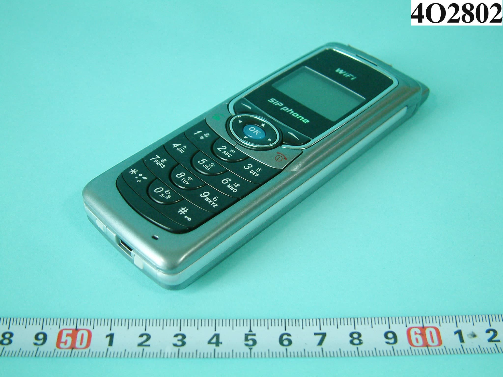
RPW-WLAN660
Nov 22, 2004WIRELESS IP PHONE
Equipment Class
DSS - Part 15 Spread Spectrum Transmitter
RPW-WLAN600
Dec 25, 2003WIRELESS IP PHONE
Equipment Class
DTS - Digital Transmission System