RPW-WLAN800Wireless Volp Phone
BCM Communication Co., Ltd.
Click to zoom
Application Details
- Equipment Class
- DTS - Digital Transmission System
- Date of Grant
- Feb 05, 2007
- Application Purpose
- Original Equipment
- Date of Application
- Feb 05, 2007
- Equipment Note
- Wireless Volp Phone
- Frequency Range
- 2412.00000000 - 2462.00000000
- Company
- BCM Communication Co., Ltd.
- Country
- Taiwan
Documents & Files
Document Text
Text extracted from the exhibit documents filed with the FCC. Open a document above to read the original.
Users Manual
Wireless VoIP Phone WLAN800 User Guide BCM Communication Co., Ltd. Phone Feature ◇ Key Features ★ Skype Supported -- . Presence . Skype Talk . Skype Out (with SkypeOut Country Code) ★ MSN Supported -- . Presence . IM . MSN Talk ★ Multiple Media Supported -- . IP TV . IP Radio . IP Camera – Web Cam Streaming ★ IE Browser Supported ★ Hot Spot Auto-Login ★ Auto Provision Supported ◇ Features ★ Phone book-- . 250 Records . with fields for name, numbers, ring tone, speed-dial, email information ★ VoIP -- . 3-Way Conferencing . Caller ID Presentation Restriction . Call Hold and Resume . Call Forward (Unconditional,Busy,Timeout) . Call Transfer . Call Waiting and Retrieve . Speed Dial ★ Multiple Languages -- . English . Spanish ★ Voice Mail Indication ★ Date & Time (NTP Time Synchronization) ★ Wallpaper ★ 10 Wireless Profiles – Auto-scan / Auto-login ★ Call History : 20 Records ★ Software Upgrade through Internet ○ ! Please note that local variations may apply. Specifications ◇ Display ★ 2.2” QVGA TFT LCD ★ 240x320 pixels with 65,536 colors ◇ Size 135 x 45 x 18 mm ◇ Weight 120 g / 4.2 oz ◇ Power ★ 3.7V 1250mAh LI-ION Battery ★ 5V 1.0A AC Adapter, 100V~240V Performance Characteristics ◇ Frequency . 2.4GHz . FCC--Channel 1~11 Supported . CE—Channel 1~13 Supported . JP—Channel1~14 Supported ◇ Transmit Power 11dBm for 802.11b/g ◇ Radio Range Outdoor up to 300m via Embedded Antenna ◇ External Interface . One mini-USB Socket (For Charging Only) . One Stereo Earphone Jack ○ ! Stereo sound can only be heard with a compatible stereo headset ◇ Memory . 32MB Flash . 64MB SDRAM ○ ! Please note that actual free memory may vary due to phone pre-configuration. ◇ Voice Protocols . SIP v2 Session Initiation Protocol (RFC3261) . SDP (RFC2327) . SIP Session Keep Alive ◇ Voice Codec’s . G.711(A-law and μ -low) . G.729a/b ◇ DTMF Transmission . In-band . Out-band(RFC2833) ◇ Voice Quality . G.168 Echo Cancellation . Jitter Buffer Control (Default 180ms, Max 900ms) . VAD-Voice Activity Detection ◇ OS Microsoft Windows CE 4.2 ◇ Management Features . AES or SSL Encryption . HTTP/ HTTPs/ FTP Supported for Firmware Upgrade . HTTP/ HTTPs Supported for Configuration Change . Embedded Web Configuration Interface (With Password Protection) ◇ Battery Life . Standby Time up to 60 Hours . Talking Time up to 3 Hours ○ ! Battery talk and standby times are estimates only and depend on network configuration, signal strength, features used, batter y age and condition, charging practices, temperatures to which batte ry is exposed, and many other factors. Please note that the amount of time a phone is used for calls, Skype, or MSN will affect its standby time. Likewise, the amount of time that the pho ne is turned on and in standby mode will affect its talk time. Network Characteristics ◇ Network Protocols TCP/UDP/IP, IPV4, DNS, SDP, ARP, ICMP, DHCP Client, Static IP ◇ Security . WEP (64 and 128 bit) . WPA-PSK Encryption Supported 1 Center Key / Navigation Pad ̇ For a quick access to start Wi-Fi connec tion, or Open IE at the stand-by mode ̇ To activate a selected item or confirm an entry. ̇ Use Navigation pad to scroll items on the current menu. ̇ Use Navigation pad to control t he cursor for a webpage. 2 Left Soft Key ̇ To open Menu at stand-by mode ̇ To select an action item shown on the current menu. ̇ To Edit or activate Option of a selected item. 3 Right Soft Key ̇ For a quick access to Phonebook. ̇ To Return or Exit from th e current menu by layers. 4 Answer / Make-Call Key ̇ To answer or make calls. 5 Power / End-Call Key ̇ Press and Hold for few seconds to Power On/Off your phone. ̇ To end a call. ̇ To exit the current menu and skip back to stand-by screen directly. 6 Voice Mail Fast Dial Key (Numeric Key "1") ̇ Press and Hold for few seconds to speed dial for voice mail. 7 Alphanumeric Keypad ̇ 0~9 input number and characters 8 Numeric / Alpha Turn Key ̇ Press twice to enter the sign " + " befor e a country code while making a call. ̇ To switch between capital(A,B,C)/lower case(a,b,c) letters, and numbers(1,2,3) 9 Symbol Selection or Space Key ̇ Press and hold for few seconds to Lock Keypad ̇ To open the Symbol selection menu. 10 Screen Light Control Button ̇ To keep the screen light on while IP TV, IP Radio, or IE performing. 11 Volume Adjustment Buttons ̇ To a d j u s t Vo l u m e . Information Bar 1. Wireless Signal Strength ̇ Indicates current Wi-Fi (also WiFi,wifi,etc.) netwo rk signal strength. 2 Clock & Date ̇ Displays current time and date. Synchroniza tion can occur only when connecting to the internet. Within Phon e Settings you can set the time properties in "Date &Time" settings. 3 Phone Status ̇ Displays current Communicato r information at stand-by screen. "Skype","MSN" or "Ready" means you are available for Skype/MSN/SIP calls (Meanwhile the power LED will flash in blue.) When th e power LED flashes in red means you are not available for all communicators. ̇ Displays a highlighted item for acti on when you navigate through menus. 4 Battery Status ̇ Indicates current status of battery power remains. 5 Network Name (SSID) ̇ Displays the SSID you selected to connect. 6 SIP Phone Number ̇ Displays your SIP number pr ovided by your service prov ider when you register on a SIP server successfully. If not, t he indicator will not be shown. Tool Bar 7 Left Soft Key Action ̇ Indicates the action of cu rrent menu Generally for "S elect" or "Edit" usages. At the stand-by mo de, it is user menu access. 8 Right Soft Key Action ̇ Indicates the action of cu rrent menu Generally for "R eturn" or "Exit" usages. At the stand-by mode , it is Phonebook quick access. ̇ Auto Hot-Spot Log-in <Hint> Menu --> Phone Se ttings --> Wireless --> Hotspot <Note>When you stay in a Hotspot coverage, the unit will pop out IE browser to notify and log in automatically. 1 If you already have a Ho tspot account, select the Hotspot in "Settings." 2 A list of settings will be displayed. Edit your account information, press Center key to save and the…
Text truncated - open the document above for the full version.
External Photos
Project No.: 0609066 Page 2 of 16 Neutron Engineering Inc. 0609066 Project No.: 0609066 Page 3 of 16 Neutron Engineering Inc. 0609066 0609066 Project No.: 0609066 Page 15 of 16 Neutron Engineering Inc. 0609066 0609066 Project No.: 0609066 Page 16 of 16 Neutron Engineering Inc. 0609066 Project No.: 0609066 Page 9 of 16 Neutron Engineering Inc. 0609066 0609066 Project No.: 0609066 Page 12 of 16 Neutron Engineering Inc. 0609066 0609066 Project No.: 0609066 Page 13 of 16 Neutron Engineering Inc. 0609066 Project No.: 0609066 Page 14 of 16 Neutron Engineering Inc. 0609066 0609066
ID Label/Location Info
Neutron Engineering Inc. FCC ID: RPW-WLAN800 Label Sample The remained portion of label statement required by FCC is attached in the user’s manual Label Location 28.5 mm 2 mm
Internal Photos
Project No.: 0609066 Page 4 of 16 Neutron Engineering Inc. 0609066 0609066 Project No.: 0609066 Page 5 of 16 Neutron Engineering Inc. 0609066 0609066 Project No.: 0609066 Page 6 of 16 Neutron Engineering Inc. 0609066 0609066 Project No.: 0609066 Page 7 of 16 Neutron Engineering Inc. 0609066 Project No.: 0609066 Page 8 of 16 Neutron Engineering Inc. 0609066 0609066 Project No.: 0609066 Page 10 of 16 Neutron Engineering Inc. 0609066 0609066 Project No.: 0609066 Page 11 of 16 Neutron Engineering Inc. 0609066 0609066
Operational Description
Part Number : WLM02 Subject : WLAN module 1.CPU, U3, 88W8385 operation frequency is external 40MHz Crystal clock CXO for reference requency; this crystal is also used for RF module. This chip is responsible to control RF- Baseband Transceiver (88W8385). The 88W8385 supports SDIO interfaces, supports 802.11e Quality of service(QoS) 2. EEPROM, U5, M95080-WDW6TP,1k*8bits EEPROM. It is used to store the normal and test firmware. 3. Integrated 2.4GHz ISM Band RF- Baseband Transceiver, U1, 88W8015 which is integrated all RF- Baseband receive and Transmit function. It is also integrated programmable frequency synthesizers with integrated VCOs, I/Q generation and CMOS up/down conversion mixers. 4. 88W8015 support 802.11b/g, WLAN chipset solutions. 5. Power part :There are several regulators are used on the board.U4,R1170H331B-3.3V,U12,R1170H281B-2.8V, U10,R1131N151D-1.5V for 8W8385+8W8015 chip LDO. 6. Chip Balun 50 ohm unbalanced,50 ohm balanced BA1,LDB212G4005C-001.Ferq range 2.4GHz ±100MHz 7. Band -Pass Filters, BP2, LFB2H2G45SG7A159, Freq. Range: 2.4~2.5GHz; IL@BW: 2.1dB 8. GaAs IC SPDT Switch, U9, AS179-92LF, features low insertion loss and positive voltage operation with very low DC power consumption.
RF Exposure Info
©2005 A Test Lab Techno Corp. Page 1 of 76 This report shall not be reproduced except in full, without the written approval of A Test Lab Techno Corp. Rev.00 This document may be altered or revised by A Test Lab Techno. Corp. personnel only, and shall be noted in the revision section of the document A Test Lab Techno Corp. Changan Lab:No. 140 -1, Changan Street, Bade City, Taoyuan County, Taiwan R.O.C. Te l:886-(0)3-271-0188 / Fax:886-(0)3-271-0190 SAR EVALUATION REPORT! Test Report No. : 0701FS15 Applicant : BCM Communication Co., Ltd. FCC ID : RPW-WLAN800 Model Name : Wireless VOIP Phone Trade Mark : BCM Model Number : WLAN 800 Dates of Test : Jan.08-10,2007 Test Environment : Ambient Temperature: 22 ±3 ° C Relative Humidity:40 - 70 % Test Specification : Standard C95.1-1999 IEEE Std. 1528-2003 Max. SAR : 0.146 W/kg WLAN Head SAR(802.11b) 0.058 W/kg WLAN Head SAR(802.11g) 0.052 W/kg WLAN Body SAR(802.11b) 0.015 W/kg WLAN Body SAR(802.11g) FCC Rule Part(s) : 2.1093;FCC/OET Bulletin 65 Supplement C [July 2001] Test Lab : Changan Lab 1. The test operations have to be performed with cautious behavior, the test results are as attached. 2. The test results are under chamber environment of A Test Lab Techno Corp. A Test Lab Techno Corp. does not assume responsibility for any conclusions and generalizations drawn from the test results with regard to other specimens or samples. 3. The measurement report has to be written approval of A Test Lab Techno Corp. It may only be reproduced or published in full. Country Huang 20070117 Sam Chuang 20070117 Measurement Center Manager Testing Engineer Test Report No:0701FS15 Page 2 of 76 ©2005 A Test Lab Techno Corp. Contents 1. Description of Equipment Under Test (EUT).......................................................................................... 3 2. Other Accessories..................................................................................................................................... 4 3. Introduction................................................................................................................................................ 5 4. SAR Definition........................................................................................................................................... 6 5. SAR Measurement Setup.......................................................................................................................... 7 6. System Components................................................................................................................................. 9 6.1 DASY4 E-Field Probe System........................................................................................................... 9 6.1.1 ET3DV6 E-Field Probe Specification....................................................................................... 10 6.1.2 ET3DV6 E-Field Probe Calibration.......................................................................................... 11 6.2 Data Acquisition Electronic (DAE) System......................................................................................... 11 6.3 Robot.................................................................................................................................................. 12 6.4 Measurement Server.......................................................................................................................... 12 6.5 Device Holder for Transmitters.......................................................................................................... 12 6.6 Phantom-TWIN SAM V4.0................................................................................................................. 13 6.7 Data Storage and Evaluation............................................................................................................. 13 6.7.1 Data Storage............................................................................................................................ 13 6.7.2 Data Evaluation........................................................................................................................ 14 7. Test Equipment List.................................................................................................................................. 16 8. Tissue Simulating Liquids........................................................................................................................ 17 8.1 Liquid Confirmation............................................................................................................................ 18 8.1.1 Parameters............................................................................................................................... 18 8.1.2 Liquid Depth............................................................................................................................. 19 9. Measurement Process.............................................................................................................................. 20 9.1 Device and Test Conditions................................................................................................................ 20 9.2 System Performance Check.............................................................................................................. 21 9.2.1 Symmetric Dipoles for System Validation................................................................................ 21 9.2.2 Validation.................................................................................................................................. 22 9.3 Dosimetric Assessment Setup........................................................................................................... 23 9.3.1 Headset Test Position - Body Worn.......................................................................................... 23 9.3.2 Measurement Procedures.........................................................…
Text truncated - open the document above for the full version.
Test Report
Report No.: NEI-FCCP-1-0609066 Page 2 of 183 Neutron Engineering Inc. Declaration Neutron represents to the client that testing is done in accordance with standard procedures as applicable and that test instruments used has been calibrated with the standards traceable to National Measurement Laboratory (NML) of R.O.C., or National Institute of Standards and Technology (NIST) of U.S.A. Neutron's reports apply only to the specific samples tested under conditions. It is manufacture’s responsibility to ensure that additional production units of this model are manufactured with the identical electrical and mechanical components. Neutronshall have no liability for any declarations, inferences o r generalizations drawn by the client or others from Neutron issued reports. Neutron’s reports must not be used by the client to claim product endorsement by the authorities or any agency of the Government. This report is the confidential property of the client. As a mutual protection to the clients, the public and Neutron-self, extracts from the test report shall not be reproduced except in full with Neutron’s authorized written approval. Neutron’s laboratory quality assurance procedures are in compliance with the ISO Guide 17025 requirements, and accredited by the conformity assessment authorities listed in this test report. Limitation For the use of the authority's logo is limited unless the Test Standard(s)/Scope(s)/Item(s) mentioned in this test report is (are) included in the conformity assessment authorities acceptance respective. Report No.: NEI-FCCP-1-0609066 Page 3 of 183 Neutron Engineering Inc. Table of Contents Page 1 . CERTIFICATION 5 2 . SUMMARY OF TEST RESULTS 6 2.1 TEST FACILITY 7 2.2 MEASUREMENT UNCERTAINTY 7 3 . GENERAL INFORMATION 8 3.1 GENERAL DESCRIPTION OF EUT 8 3.2 DESCRIPTION OF TEST MODES 9 3.3 BLOCK DIGRAM SHOWING THE CONFIGURATION OF SYSTEM TESTED 10 3.4 DESCRIPTION OF SUPPORT UNITS 11 4 . EMC EMISSION TEST 12 4.1 CONDUCTED EMISSION MEASUREMENT 12 4.1.1 POWER LINE CONDUCTED EMISSION LIMITS 12 4.1.2 MEASUREMENT INSTRUMENTS LIST 12 4.1.3 TEST PROCEDURE 13 4.1.4 DEVIATION FROM TEST STANDARD 13 4.1.5 TEST SETUP 13 4.1.6 EUT OPERATING CONDITIONS 14 4.1.7 TEST RESULTS 15 4.2 RADIATED EMISSION MEASUREMENT 27 4.2.1 RADIATED EMISSION LIMITS 27 4.2.2 MEASUREMENT INSTRUMENTS LIST 28 4.2.3 TEST PROCEDURE 28 4.2.4 DEVIATION FROM TEST STANDARD 28 4.2.5 TEST SETUP 29 4.2.6 EUT OPERATING CONDITIONS 29 4.2.7 TEST RESULTS (Between 30 – 1000 MHz) 30 4.2.8 TEST RESULTS (Above 1000 MHz) 42 4.2.9 TEST RESULTS (Restricted Bands Requirements) 150 5 . BANDWITH TEST 158 5.1 APPLIED PROCEDURES / LIMIT 158 5.1.1 MEASUREMENT INSTRUMENTS LIST 158 5.1.2 TEST PROCEDURE 158 5.1.3 DEVIATION FROM STANDARD 158 5.1.4 TEST SETUP 158 5.1.5 EUT OPERATION CONDITIONS 158 5.1.6 TEST RESULTS 159 Report No.: NEI-FCCP-1-0609066 Page 4 of 183 Neutron Engineering Inc. Table of Contents Page 6 . PEAK OUTPUT POWER TEST 163 6.1 APPLIED PROCEDURES / LIMIT 163 6.1.1 MEASUREMENT INSTRUMENTS LIST 163 6.1.2 TEST PROCEDURE 163 6.1.3 DEVIATION FROM STANDARD 163 6.1.4 TEST SETUP 163 6.1.5 EUT OPERATION CONDITIONS 163 6.1.6 TEST RESULTS 164 7 . ANTENNA CONDUCTED SPURIOUS EMISSION 168 7.1 APPLIED PROCEDURES / LIMIT 168 7.1.1 MEASUREMENT INSTRUMENTS LIST 168 7.1.2 TEST PROCEDURE 168 7.1.3 DEVIATION FROM STANDARD 168 7.1.4 TEST SETUP 168 7.1.5 EUT OPERATION CONDITIONS 168 7.1.6 TEST RESULTS 169 8 . POWER SPECTRAL DENSITY TEST 171 8.1 APPLIED PROCEDURES / LIMIT 171 8.1.1 MEASUREMENT INSTRUMENTS LIST 171 8.1.2 TEST PROCEDURE 171 8.1.3 DEVIATION FROM STANDARD 171 8.1.4 TEST SETUP 171 8.1.5 EUT OPERATION CONDITIONS 171 8.1.6 TEST RESULTS 172 9 . RF EXPOSURE TEST 176 9.1 APPLIED PROCEDURES / LIMIT 176 9.1.1 MEASUREMENT INSTRUMENTS LIST 176 9.1.2 TEST RESULTS 177 10 .BAND EDGES REQUIREMENTS TEST 178 10.1 APPLIED PROCEDURES / LIMIT 178 10.1.1 MEASUREMENT INSTRUMENTS LIST 178 10.1.2 TEST RESULTS 179 11 . EUT TEST PHOTO 180 Report No.: NEI-FCCP-1-0609066 Page 5 of 183 Neutron Engineering Inc. 1. CERTIFICATION E q u i p m e n t : Wireless VoIp Phone Trade Name : BCM M o d e l N o . : WLAN 800 A p p l i c a n t : BCM Communication Co., Ltd. Data of Test : Sep. 14, 2006 ~ Nov. 21, 2006 Te s t I t e m : ENGINEERING SAMPLE Standards : FCC Part15, Subpart C / RSS-210: 2004/ ANCI C63.4 : 2003 The above equipment has been tested and found compliance with the requirement of the relative standards by Neutron Engineering Inc. EMC Laboratory. The test data, data evaluation, and equipment configuration contained in our test report (Ref No. NEI-FCCP-1-0609066) were obtained utilizing the test procedures, test instruments, test sites that has been accredited by the Authority of NVLAP and CNLA according to the ISO-17025 quality assessment standard and technical standard(s). Report No.: NEI-FCCP-1-0609066 Page 6 of 183 Neutron Engineering Inc. 2. SUMMARY OF TEST RESULTS Test procedures according to the technical standards: FCC Part15, Subpart C Standard Section Test Item Judgment Remark 15.207 Conducted Emission PASS 15.247 (c) Antenna conducted Spurious Emission PASS 15.247 (a)(2) 6dB Bandwidth PASS 15.247 (b) Peak Output Power PASS 15.247 (c) Radiated Spurious Emission PASS 15.247 (d) Power Spectral Density PASS 15.203 Antenna Requirement PASS 1.1307 1.1310 2.1091 2.1093 RF Exposure Compliance PASS NOTE: (1)” N/A” denotes test is not applicable in this Test Report Report No.: NEI-FCCP-1-0609066 Page 7 of 183 Neutron Engineering Inc. 2.1 TEST FACILITY The test facilities used to collect the test data in this report is C01/OS02 at the location of No.132-1, Lane 329, Sec. 2, Palain Road, Shijr City, Taipei, Taiwan. 2.2 MEASUREMENT UNCERTAINTY The reported uncertainty of measurement y ± U,where expended uncertainty U is based on a standard uncertainty multiplied by a coverage factor of k=2,providing a level of confidence of approximately 95 %。 A. Conducted Measurement : Test Site Method Measurement Frequency Range U,(dB) NOTE C01 ANSI150 KHz ~ 30MHz 1.94 B. Radiate…
Text truncated - open the document above for the full version.
Test Report
Report No.: NEI-FCCP-1-0609066 Page 91 of 183 Neutron Engineering Inc. Orthogonal Axes:Z 802.11b/CH11(Above 1000 MHz, Vertical) Report No.: NEI-FCCP-1-0609066 Page 92 of 183 Neutron Engineering Inc. Orthogonal Axes:Z 802.11b/CH11(Above 1000 MHz, Vertical) Report No.: NEI-FCCP-1-0609066 Page 93 of 183 Neutron Engineering Inc. EUT: Wireless VoIp Phone Model No. : WLAN 800 Temperature: 25 °C Relative Humidity: 60 % Pressure: 1009 hPa Te s t P o w e r : AC 120V/60Hz Test Mode : 802.11b/CH11 Freq.Ant.Pol.Ant./CF PeakAVPeakAVPeakAV (MHz)H/V(dBuV) (dBuV) CF(dB) (dBuV/m) (dBuV/m) (dBuV/m) (dBuV/m) 1025.00H48.86*-8.9339.93*74.0054.00Z/H 1290.00H47.84*-7.7240.12*74.0054.00Z/H 1665.00H46.88*-5.8441.04*74.0054.00Z/H 1795.00H47.95*-5.1242.83*74.0054.00Z/H 2155.00H47.56*-3.5943.97*74.0054.00Z/H 2840.00H47.59*-1.3746.22*74.0054.00Z/H 4917.00H46.5841.353.3549.9344.7074.0054.00Z/H 7386.00H41.85*8.1349.98*74.0054.00Z/H 9848.00H41.9828.9910.1352.1139.1274.0054.00Z/H Note ReadingAct.Limit Remark: (1) Spectrum Setting : 30MHz – 1000MHz , RBW= 100KHz, VBW=100KHz, Sweep time = 200 ms. 1GHz- 25GHz, RBW= 1MHz, VBW= 1MHz, Sweep time = 200 ms (2) All readings are Peak unless otherwise stated QP in column of『Note』. Peak denotes that the Peak reading compliance with the QP Limits and then QP Mode measurement didn‘t perform。 (3) Measuring frequency range from 30MHz to 1000MHz or the 10th harmonic of highest fundamental frequency。“F” denotes fundamental frequency; “H” denotes spurious frequency. “E” denotes band edge frequency. (This judgment method includes the Band Edge Requirement.) (4) Radiated emissions measured in frequency range above 1000MHz were made with an instrument using Peak detector mode and AV detector mode of the emission 。 (5) Data of measurement within this frequency range shown “ * ” in the table above means the reading of emissions are attenuated more than 20dB below the permissible limits or the field strength is too small to be measured. (6) A preamp and high pass filter were used for this test in order to provide sufficient measurement sensitivity. (7) EUT Orthogonal Axes: “X” - denotes Laid on Table;”Y” - denotes Vertical Stand;”Z” - denotes Side Stand Report No.: NEI-FCCP-1-0609066 Page 94 of 183 Neutron Engineering Inc. Orthogonal Axes:Z 802.11b/CH11(Above 1000 MHz, Horizontal) Report No.: NEI-FCCP-1-0609066 Page 95 of 183 Neutron Engineering Inc. Orthogonal Axes:Z 802.11b/CH11 (Above 1000 MHz, Horizontal) Report No.: NEI-FCCP-1-0609066 Page 96 of 183 Neutron Engineering Inc. EUT: Wireless VoIp Phone Model No. : WLAN 800 Temperature: 25 °C Relative Humidity: 60 % Pressure: 1009 hPa Te s t P o w e r : AC 120V/60Hz Test Mode : 802.11g/CH01 Freq.Ant.Pol.Ant./CF PeakAVPeakAVPeakAV (MHz)H/V(dBuV) (dBuV) CF(dB) (dBuV/m) (dBuV/m) (dBuV/m) (dBuV/m) 1070.00V48.06*-8.7239.34*74.0054.00X/H 1270.00V48.41*-7.8140.60*74.0054.00X/H 1665.00V47.13*-5.8441.29*74.0054.00X/H 1750.00V48.38*-5.3743.01*74.0054.00X/H 2110.00V47.38*-3.7043.68*74.0054.00X/H 2670.00V47.59*-2.0445.55*74.0054.00X/H 4826.00V45.3635.153.1348.4938.2874.0054.00X/H 7236.00V41.42*7.4748.89*74.0054.00X/H 9648.00V42.1729.109.9752.1439.0774.0054.00X/H Note ReadingAct.Limit Remark: (1) Spectrum Setting : 30MHz – 1000MHz , RBW= 100KHz, VBW=100KHz, Sweep time = 200 ms. 1GHz- 25GHz, RBW= 1MHz, VBW= 1MHz, Sweep time = 200 ms (2) All readings are Peak unless otherwise stated QP in column of『Note』. Peak denotes that the Peak reading compliance with the QP Limits and then QP Mode measurement didn‘t perform。 (3) Measuring frequency range from 30MHz to 1000MHz or the 10th harmonic of highest fundamental frequency。“F” denotes fundamental frequency; “H” denotes spurious frequency. “E” denotes band edge frequency. (This judgment method includes the Band Edge Requirement.) (4) Radiated emissions measured in frequency range above 1000MHz were made with an instrument using Peak detector mode and AV detector mode of the emission 。 (5) Data of measurement within this frequency range shown “ * ” in the table above means the reading of emissions are attenuated more than 20dB below the permissible limits or the field strength is too small to be measured. (6) A preamp and high pass filter were used for this test in order to provide sufficient measurement sensitivity. (7) EUT Orthogonal Axes: “X” - denotes Laid on Table;”Y” - denotes Vertical Stand;”Z” - denotes Side Stand Report No.: NEI-FCCP-1-0609066 Page 97 of 183 Neutron Engineering Inc. Orthogonal Axes:X 802.11g/CH01(Above 1000 MHz, Vertical) Report No.: NEI-FCCP-1-0609066 Page 98 of 183 Neutron Engineering Inc. Orthogonal Axes:X 802.11g/CH01(Above 1000 MHz, Vertical) Report No.: NEI-FCCP-1-0609066 Page 99 of 183 Neutron Engineering Inc. EUT: Wireless VoIp Phone Model No. : WLAN 800 Temperature: 25 °C Relative Humidity: 60 % Pressure: 1009 hPa Te s t P o w e r : AC 120V/60Hz Test Mode : 802.11g/CH01 Freq.Ant.Pol.Ant./CF PeakAVPeakAVPeakAV (MHz)H/V(dBuV) (dBuV) CF(dB) (dBuV/m) (dBuV/m) (dBuV/m) (dBuV/m) 1065.00H48.46*-8.7439.72*74.0054.00X/H 1165.00H48.24*-8.2939.95*74.0054.00X/H 1555.00H46.85*-6.4540.40*74.0054.00X/H 1850.00H47.63*-4.8142.82*74.0054.00X/H 1985.00H48.02*-4.0643.96*74.0054.00X/H 2650.00H48.03*-2.1245.91*74.0054.00X/H 4813.00H44.3234.123.0947.4137.2174.0054.00X/H 7236.00H41.48*7.4748.95*74.0054.00X/H 9648.00H41.57*9.9751.54*74.0054.00X/H Note ReadingAct.Limit Remark: (1) Spectrum Setting : 30MHz – 1000MHz , RBW= 100KHz, VBW=100KHz, Sweep time = 200 ms. 1GHz- 25GHz, RBW= 1MHz, VBW= 1MHz, Sweep time = 200 ms (2) All readings are Peak unless otherwise stated QP in column of『Note』. Peak denotes that the Peak reading compliance with the QP Limits and then QP Mode measurement didn‘t perform。 (3) Measuring frequency range from 30MHz to 1000MHz or the 10th harmonic of highest fundamental frequency。“F” denotes fundamental frequency; “H” denotes spurious frequency. “E” denotes band edge frequency. (This judgment method includes the Band Edge Requirement.) (4) Radiated emissions measured in frequency range ab…
Text truncated - open the document above for the full version.
Test Setup Photos
Report No.: NEI-FCCP-1-0609066 Page 180 of 183 Neutron Engineering Inc. 11. EUT TEST PHOTO Conducted Measurement Photos Report No.: NEI-FCCP-1-0609066 Page 181 of 183 Neutron Engineering Inc. Radiated Measurement Photos X Report No.: NEI-FCCP-1-0609066 Page 182 of 183 Neutron Engineering Inc. Radiated Measurement Photos Y Report No.: NEI-FCCP-1-0609066 Page 183 of 183 Neutron Engineering Inc. Radiated Measurement Photos Z
Contact Information
Applicant
Frank Chou(Senior Product Manag)
Test Firm
BTL Inc.Andy Yeh
Technical Specifications
| # | Rule Parts | Frequency Range | Power Output |
|---|---|---|---|
| 1 | 15C | 2.41 GHz - 2.46 GHz | 33.00 mW |
Other Applications from BCM Communication Co., Ltd.

RPW-CM210
Jun 01, 2026Instant Color Picking
Equipment Class
DTS - Digital Transmission System
RPW-BTG200
Nov 18, 2020BTG200
Equipment Class
DTS - Digital Transmission System
RPW-WIGO800I
Sep 11, 2007GSM/WiFi Dual-mode IP Media Phone
Equipment Class
PCE - PCS Licensed Transmitter held to ear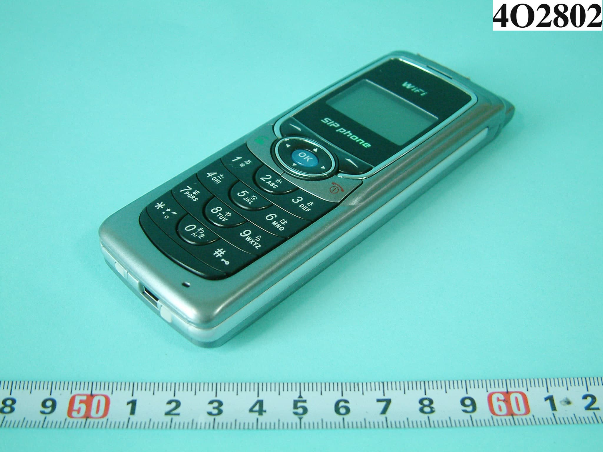
RPW-WLAN660
Nov 22, 2004WIRELESS IP PHONE
Equipment Class
DSS - Part 15 Spread Spectrum Transmitter
RPW-WLAN600
Dec 25, 2003WIRELESS IP PHONE
Equipment Class
DTS - Digital Transmission System