RQKWUBR-506NWIRELESS LAN MODULE
Sammi Information Systems Co, Ltd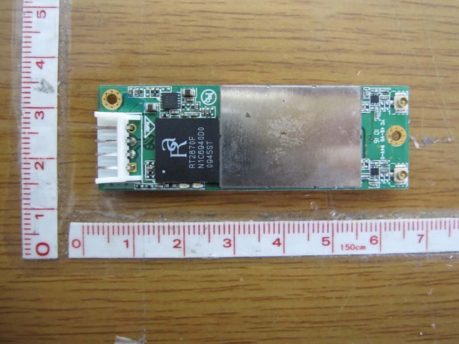
Click to zoom
Application Details
- Equipment Class
- DTS - Digital Transmission System
- Date of Grant
- Dec 05, 2010
- Application Purpose
- Original Equipment
- Date of Application
- Dec 02, 2010
- Equipment Note
- WIRELESS LAN MODULE
- Frequency Range
- 5745.00000000 - 5825.00000000
- Country
- South Korea
Documents & Files
Document Text
Text extracted from the exhibit documents filed with the FCC. Open a document above to read the original.
Users Manual
FCC Information to User This equipment has been tested and found to comply with the limits for a Class B digital device, pursuant to Part 15 of the FCC Rules. These limits are designed to provide reasonable protection against harmful interference in a residential installation. This equipment generates, uses and can radiate radio frequency energy and, if not installed and used in accordance with the instructions, may cause harmful interference to radio communications. However, there is no guarantee that interference will not occur in a particular installation. If this equipment does cause harmful interference to radio or television reception, which can be determined by turning the equipment off and on, the user is encouraged to try to correct the interference by one of the following measures: • Reorient or relocate the receiving antenna. • Increase the separation between the equipment and receiver. • Connect the equipment into an outlet on a circuit different from that to which the receiver is con-nected. • Consult the dealer or an experienced radio/TV technician for help. Caution Modifications not expressly approved by the party responsible for compliance could void the user’s authority to operate the equipment. FCC Compliance Information : This device complies with Part 15 of the FCC Rules. Operation is subject to the following two conditions: (1) This device may not cause harmful interference, and (2) this device must accept any interference received, including interference that may cause undesired operation IMPORTANT NOTE: FCC RF Radiation Exposure Statement: This equipment complies with FCC RF radiation exposure limits set forth for an uncontrolled environment. This equipment should be installed and operated with a minimum distance of 20 centimeters between the radiator and your body.This transmitter must not be co-located or operating in conjunction with any other antenna or transmitter. 1.1 How to install and work with wireless network? Wireless LAN is an standard feature available with SmartStation. Wireless LAN card installed to USB Interface. It is necessary to install driver on the SmartStation before using Wireless LAN. Installation of wireless network driver Insert the driver CD given with the LAN card to CD ROM drive which is connected to SmartStation. • Click Install Driver to begin device driver installation. •Please wait for a while during the Setup Wizard is preparing the setup. •Please read the following license agreement. Use the scroll bar to view the rest of this agreement. Click Yes to accept the agreement. •In Windows XP, there is a Windows Zero Configuration Tool for you to setup wireless adapter. You can choose to configure the adapter through the Microsoft Zero Configuration Tool or the Ralink Configuration Tool. It is recommended to choose the Ralink Configuration Tool for the adapter. Click Next to continue. •If you need the adapter to operate with better performance, please choose Optimize for performance mode to enable the Tx Burst mode. Or you can choose Optimize for WiFi mode to run in standard wireless network. •Please wait for a while during the adapter is configuring your new software installation. •When the adapter is installed properly, the configuration utility will be displayed automatically. •After the setup has finished the installing and click Finish button. 1.2 Wireless Network Configuration Utility The Configuration Utility is a powerful application that helps you to configure the Wireless USB 2.0 adapter and monitor the link status and statistics during the communication process. When the USB adapter is installed, the configuration utility will be displayed automatically. This adapter will auto connect to wireless device which has better signal strength and no wireless security setting. Note: In Windows XP, there is a “Windows Zero Configuration Tool” for you to setup wireless clients. If you want to switch the configuration utilities, please follow one of the ways as below: [First Way] Right-click the icon in the system tray and select Use Zero Configuration as Configuration utility [Second Way] Right-click the icon as follow and select “View Available Wireless Networks” Click “Advanced” as below, Uncheck “Use Windows to configure my wireless network settings” to enable the utility for the adapter and then click OK to continue. Note: If “Wireless Zero Configuration” is enabled, you can only configure the advance setting or check the link status and statistics from the configuration utility of the adapter. 1.2.1 Profile In the “Profile”, you can view and manage the current using Available Point(s). You can Add, Delete, Edit, or Activate the current Available Point(s). Also you can duplicate the AP or set current AP as Default. Profiles List: The Profiles List displays all the profiles and the relative settings of the profiles including Profile Name, SSID, and Channel...etc. Profile -> Name of Profile. SSID -> AP or Ad-Hoc Name. Channel -> Channel in use for Ad-Hoc. Authentication -> Authentication mode. Encryption -> Security algorithm in use. Network Type -> Network’s type, including infrastructure and Ad-Hoc. Add/Delete/Edit Button: Click these buttons to add/delete/edit the selected profiles. Activate Button: Click ”Activate” to connect the selected profile. When a profile is activated, the adapter will be initially connected to the profile. 1.2.2 Link Status In this section, you can immediately monitor the current connected link status, such as Link Speed, Throughput, Link Quality, Signal Strength, Noise Level ...etc. Status: Display the SSID and MAC ID of the network that the adapter is connecting to. Extra Info: Display the link status. Channel: Display the number of the radio channel and the frequency used for the networking. Link Speed (Mbps): Display the transmission and reception rate of the network. The maximum transmission rate is 54Mbps. Throughput (Kbits/sec): Display data transmitted and received throughput in unit of K bits per…
Text truncated - open the document above for the full version.
Cover Letter(s)
11F Kolon Aston Bldg, 505-14, Gasan-dong,Guemcheon-Gu,Seoul,153-803 KOREA TEL No : +82 2 790-5505 FAX No : +82 2 797-9206 December 1, 2010 Timco Engineering, Inc. 849 NW State Road 45 P.O.Box 370 Newberry,m Florida 32669 LETTER OF AUTHORIZATION To whom it may concern: We, the undersigned, hereby authorize LTA Co., Ltd., to act on our behalf in all manners relating to application for equipment authorization for FCC ID: RQKWUBR-506N including signing of all documents relating to these matters. Any and all acts carried out by LTA Co., Ltd., on our behalf shall have the same affect as acts of our own. This authorization is valid until further written notice from Sammi Information Systems Co, Ltd. LTA Co.,LTD. (Contact Person) Contact name: LEE, Kyung-Taek Position: Manager Phone:(82)31-323-6008 E-mail: [email protected] Sincerely, Arthur Kim Assistant Manager
Cover Letter(s)
11F Kolon Aston Bldg, 505-14, Gasan-dong,Guemcheon-Gu,Seoul,153-803 KOREA TEL No : +82 2 790-5505 FAX No : +82 2 797-9206 December 1, 2010 Federal Communications Commission Equipment Authorization Branch 7435 Oakland Mills Road Columbia, MD 21046 In re : Sammi Information Systems Co, Ltd. FCC ID: RQKWUBR-506N Request for Confidentiality Pursuant to Sections 0.457 and 0.459 of the Commission’s Rules (CFR 47), and Section 552 (b) (4) of the Freedom of Information Act, Sammi Information Systems Co, Ltd. hereby requests confidentiality and treatment of certain information accompanying this application. The materials contain trade secrets and proprietary information not customarily released to the public. The public disclosure of these matters might be harmful to the Applicant and provide unjustified benefits to its competitors. We are also hereby request Short-Term Confidentiality for 180 days after the grant as outlined in Public Notice DA 04-1705. This provision will give Sammi Information Systems Co, Ltd. temporary confidentiality of commercially sensitive information prior to product release. The requested Confidential and Temporary Confidential exhibits are listed as follows: Exhibit Type File Name Schematics CONF APPENDIX RQKWUBR-506N SCH DIA.pdf Parts list CONF APPENDIX RQKWUBR-506N PL.pdf Block diagram CONF APPENDIX RQKWUBR-506N BLK DIA.pdf CONFIDENTIAL Operational description CONF APPENDIX RQKWUBR-506N OpDes.pdf External Photos SHORT-TERM CONF RQKWUBR-506N EXT Photo.pdf Internal Photos SHORT-TERM CONF RQKWUBR-506N INT Photo.pdf Test-Setup Photos SHORT-TERM CONF RQKWUBR-506N Test Photo.pdf SHORT-TERM CONFIDENTIAL User’s Manual SHORT-TERM CONF RQKWUBR-506N Manual.pdf The Applicant understands that pursuant to Rule 0.457, disclosure of this application and all accompanying documentations, where applicable, will not be made public before the date of the Grant for this application. Sincerely, Arthur Kim Assistant Manager
Cover Letter(s)
Sammi Information Systems Co, Ltd. 11F Kolon Aston Bldg, 505-14, Ga san-dong,Guemcheon-Gu,Seoul,153 -803 KOREA TEL No : +82 2 790-5505 FAX No : +82 2 797-9206 FCC ID: RQKWUBR-506N Request for Limited Modular approval Transmitter Module Characteristics The module will be used to the manufactured product by SparkLAN Communications, Inc. No Requirements EUT 1 Have its own RF shielding Device is equipped with metal shielding to cover RF section. Refer to external photos. 2 Have buffered modulation/data inputs (if such inputs are provided) All inputs to the modules are buffered thought logic or microprocessor inputs. 3 Have it own power supply regulation The part number of the power regulator is (CAT7117) 4 Meet the antenna requirements of Section 15.203 The ant enna connector is the reverse polarity SMA connector. 5 Be tested in a stand-alone configuration, i.e., the antenna, AC or DC power and data input/output lines must be connected to the module but, the module must not be inside another case during testing Please reference exhibition Test Conf iguration Photo for the stand-alone test configuration 6 Be labeled with its own FCC ID number, and if the FCC ID is not visible when the module is installed inside another device, then the out side of the device into which the module is installed must also display a label referring to the enclosed module Label is to be placed in front of the EUT(WUBR-5 06N ), and other label is to be placed in the User’s Guide. Refer to FCC ID label format. 7 The modular transmitter is manufactured so t hat the user cannot influence the operation of the transmitter that will operate outsi de of the scope of the regulations. Refer to “User’s Guide” 8 Address compliance with the Commission’s RF exposure limits in Sections 1.1310 and 2.1091. In addition, spread spectrum transmitters operating under Section 15.247 are required to address RF exposure compliance in accordance with Section 15.247(b)(4). Please refer exhibition RF Exposure for th e compliance of MPE RF exposure rule.
External Photos
FCC ID: RQKWUBR-506N Copyright ○ c 2010, LTA Co., Ltd. Page 1 of 2 FCC ID: RQKWUBR-506N Copyright ○ c 2010, LTA Co., Ltd. Page 2 of 2
ID Label/Location Info
FCC ID: RQKWUBR-506N Copyright Ⓒ 2010, LTA Co., Ltd. SAMPLE LABEL & LOCATION FCC ID: RQKWUBR-506N M/N: WUBR-506N Made in Korea
Internal Photos
FCC ID: WUBR-506N Copyright ○ c 2010LTA Co., Ltd. Page 1 of 1 Main Board –Front Main Board –Rear
RF Exposure Info
ATTACHMENT FCC ID: RQKWUBR-506N ** MPE Calculations ** **2.4GHz Bands Worst Case of 802.11n(40MHz) The EUT will only be used with a separation of 20 centimeters or greater between the antenna and the body of the user. The MPE calculation for this exposure is shown below. The peak radiated output power (EIRP) is calculated as follows: EIRP = P + G EIRP = 19.11dBm + (2.5)dBi EIRP = 21.61dBm Where, P = Power input to the antenna (mW) G = Power gain of the antenna (dBi) Power density at the specific separation: S = PG/(4R 2 π) S = (81.47* 1.78) / (4 * 20 2 * π) S = 0.0288mW/cm 2 Where, S = Maximum power density (mW/cm 2 ) P = Power input to the antenna (mW) G = Numeric power gain of the antenna R = Distance to the center of the radiation of the antenna (20cm = limit for MPE) The Maximum permissible exposure (MPE) for the general population is 1 mW/cm 2 . The power density at 20cm does not exceed the 1 mW/cm 2 limit. Therefore, the exposure condition is compliant with FCC rules. Estimated safe separation: R = √(PG / 4π) R = √(81.47* 1.78/ 4π) R = 3.4Cm Where, P = Power input to the antenna (mW) G = Numeric power gain of the antenna R = Distance to the center of the radiation of the antenna (20cm = limit for MPE) The numeric gain(G) of the antenna with a gain specified in dB is determined by: G = Log -1 (dB antenna gain / 10) G = Log-1 ((2.5) / 10) G = 1.78 ATTACHMENT FCC ID: RQKWUBR-506N ** MPE Calculations ** **5.0GHz Bands Worst Case of 802.11an(20MHz) The EUT will only be used with a separation of 20 centimeters or greater between the antenna and the body of the user. The MPE calculation for this exposure is shown below. The peak radiated output power (EIRP) is calculated as follows: EIRP = P + G EIRP = 15.98 dBm + (5.0)dBi EIRP = 20.98dBm Where, P = Power input to the antenna (mW) G = Power gain of the antenna (dBi) Power density at the specific separation: S = PG/(4R 2 π) S = (39.63 * 3.16) / (4 * 20 2 * π) S = 0.0249 mW/cm 2 Where, S = Maximum power density (mW/cm 2 ) P = Power input to the antenna (mW) G = Numeric power gain of the antenna R = Distance to the center of the radiation of the antenna (20cm = limit for MPE) The Maximum permissible exposure (MPE) for the general population is 1 mW/cm 2 . The power density at 20cm does not exceed the 1 mW/cm 2 limit. Therefore, the exposure condition is compliant with FCC rules. Estimated safe separation: R = √(PG / 4π) R = √(39.63 * 3.16/ 4π) R = 3.16Cm Where, P = Power input to the antenna (mW) G = Numeric power gain of the antenna R = Distance to the center of the radiation of the antenna (20cm = limit for MPE) The numeric gain(G) of the antenna with a gain specified in dB is determined by: G = Log -1 (dB antenna gain / 10) G = Log-1 ((5.0) / 10) G = 3.16
Test Setup Photos
FCC ID: RQKWUBR-506N Copyright ○ c 2010, LTA Co., Ltd. Page 1 of 1 Radiated Emission
Contact Information
Applicant
Dong-Su Park
Test Firm
LTA Co.,LtdAhn Chulho
Technical Specifications
| # | Rule Parts | Frequency Range | Power Output |
|---|---|---|---|
| 4 | 15C | 5.75 GHz - 5.83 GHz | 40.00 mW |
Other Applications from Sammi Information Systems Co, Ltd

RQK-SMART-P300U
Sep 29, 2013HANDHELD TERMINAL(INDUSTRIAL PDA)
Equipment Class
DSS - Part 15 Spread Spectrum Transmitter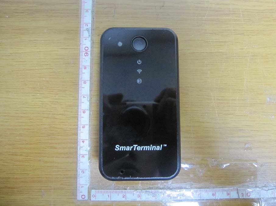
RQKSM-R400
Jul 17, 2012UHF RFID READER (BLUETOOTH EMBEDDED)
Equipment Class
DSS - Part 15 Spread Spectrum Transmitter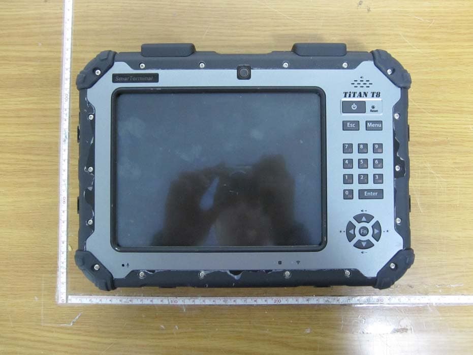
RQKTITANT8
Nov 08, 2011INDUSTRIAL TABLET COMPUTER
Equipment Class
DTS - Digital Transmission System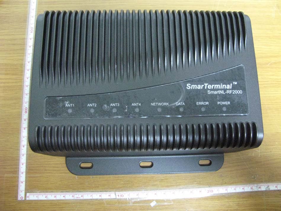
RQKSMARTNL-RF2000
Jul 07, 2010UHF-RFID READER
Equipment Class
DSS - Part 15 Spread Spectrum Transmitter
RQKSMARTRFGUNUHF
Jul 09, 2007UHF RFID Reader
Equipment Class
DSS - Part 15 Spread Spectrum Transmitter